1
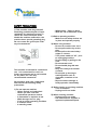
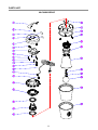
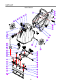
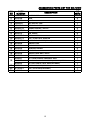
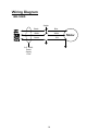
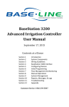
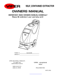
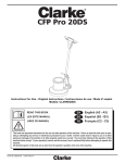
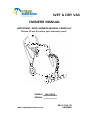
WET & DRY VAC
OWNERS MANUAL
IMPORTANT: READ OWNERS MANUAL CAREFULLY
Please fill out & return your warranty card!
MODEL#
BSL18WD
SERIAL#
www.mybrightsolutions.com
REV.01(02-13)
VA80860
TABLE OF CONTENTS
Safety Precautions
4
Handle Assembly
5
Machine Operation
6
Machine Maintenance & Storage
7
Parts Lists
Wiring Diagram
8-13
14
SAFETY PRECAUTIONS
!!! This machine must be grounded!
Grounding provides the path of least
resistance for electrical current. To
reduce the risk of electrical shock
should the machine malfunction, the
machine has a special grounding plug.
Do not remove the ground pin under
any circumstances!
- Without bag / filters in place.
- With the use of extension cords.
2) Before operating machine:
- Make sure all safety devices are
in place and operate properly.
3) When using machine:
- Do not run machine over cord.
- Do not pull machine by cord or
plug.
- Do not pull cord around sharp
edges or corners.
- Turn power switch to “off “ prior
to unplugging machine.
- Do not unplug by pulling on the
cord.
- Do not stretch cord.
- Do not handle plug with wet
hands.
- Keep cord away from heated
surfaces.
- Do not pick up burning or
smoking debris such as
cigarettes, matches or hot
ashes.
- Report machine damage or
faulty operation immediately.
This machine is intended for commercial
use. It is constructed for use in an
indoor environment and is not intended
for any other use. Use only
recommended accessories.
All operators shall read, understand
and exercise the following safety
precautions:
4) Before leaving or servicing machine:
- Turn off machine.
- Unplug cord from outlet.
1) Do not operate machine:
- Unless trained and authorized
- Unless you have read and
understand operators manual
- In flammable or explosive areas.
- With damaged cord or plug.
- If not in proper operating condition.
- In outdoor areas.
- In standing water.
5) When servicing machine:
- Unplug cord from outlet.
- Use manufacturer supplied or
approved replacement parts.
4
HANDLE ASSEMBLY
HANDLE ASSEMBLY INSTRUCTIONS
Figure 4
Figure 1
Figure 2
Figure 3
Attaching Handle
1] Remove handle from ship position and remove upper handle mounting screws
from machine (Figure 1).
2] Realign handle as shown and replace screws & washers (Figure 2).
3] Attach rear hose dump clamp (Figure 3).
4] Attach front mount squeegee (Figure 4).
5
Operation of Wet & Dry Vacuum
machine.
* Read operators manual thoroughly prior to
operating or servicing this machine.
* The shovelnose wet –dry vacuum includes
the GV25014”bubble buster” blue nylon foam
suppression bag. This bag must be used in all
wet pick-up applications. Failure to use the bag
will void the warranty on the vacuum motor.
WET PICKUP
1] Remove vacuum head and remove the cloth
or paper filter from vacuum, install the
bubble buster.
2] While vacuum head is removed, check to
make sure that the float shut-off is
unobstructed and fully functional.
3] Replace vacuum head and latch it in place.
4] Connect vacuum hose to inlet on the
machine body.
5] Attach appropriate accessory tool for the
job to be completed.
6] Plug power cord into a grounded outlet.
DRY PICKUP
1] Remove vacuum head and bubble buster,
and be sure the cloth or paper filter is
properly installed.
* Do not operate machine without bag or filter
properly installed.
2] Replace vacuum head and latch it in place.
3] Connect vacuum hose to inlet on the
machine body.
4] Attach appropriate accessory tool for the
job to be completed.
5] Plug power cord into a grounded outlet.
* Do not use an extension cord in conjunction
with the standard power cord.
7] If using the front-mounted squeegee
assembly, be sure that squeegee is attached
to front of machine.
8] If using the front-mounted squeegee
assembly, lower squeegee to the floor by
depressing the top half of the pedal [rear of
the machine] forward with your foot.
9] Turn power switch to “on” position.
10] During wet pickup, the float shut-off will
automatically prevent water from entering
the recovery tank once the recovery tank is
full.
* Do not use an extension cord in conjunction
with the standard power cord.
6] Turn power switch to “on” position.
7] Check the filter bag periodically to see if it is
full. For optimal performance, replace bag
when it is 3/4 full.
DRAINING THE RECOVERY TANK
1] Unplug machine from power outlet.
2] Transport machine to nearest floor drain or
bucket.
3] Remove drain hose from rear of machine.
Remove ball plug from drain hose, and drain
the contents of the tank.
4] After the contents have drained, remove
the vacuum head and rinse recovery tank
with clean water.
5] Replace the ball plug on the drain hose and
hang hose back on the rear of the machine.
* If foam develops in the recovery tank during
wet vacuuming, use de-foamer chemical to
help eliminate the foam. Foam will not activate
the float shut-off, and therefore, may cause
vacuum motor damage.
11] To raise the squeegee assembly back to
transport position, depress the bottom half of
the pedal [rear of the machine] downward with
your foot.
l To prevent odors in the recovery tank,
remove the vacuum head when machine is
not in operation to allow air to circulate.
* Be sure that the handle is properly
assembled on machine body prior to operating
6
MAINTENANCE
To keep the machine performing well for many
years,
please
follow
the
following
maintenance procedures.
* Always confirm that the machine is
unplugged prior to performing any
maintenance or repairs.
1] Drain and rinse recovery tank after each
use.
2] Clean float shut-off after each use.
3] Check bag to see if it is full after each use.
Replace bag when it is 3/4 full.
4] Clean outside of machine with a mild
cleaner.
5] Check power cord for any damage. If any .
6] Clean squeegee blades with a cloth.
* Do not use your fingers to wipe the blades!
7] Check vacuum hose for holes and clogs.
8] Lubricate wheels, casters and axles with a
water resistant lubricant every month.
9] Check machine for loose or missing nuts
and bolts, and replace as necessary.
* After each use in a wet pick-up application,
remove the GV25014 “Bubble Buster” blue
nylon foam suppression bag and rinse it with
clean water. This will aid in preventing any
build-up which can reduce air flow.
STORAGE
1] Unplug machine from power source.
2] Store in upright position in a dry area.
3] Store with squeegee assembly off the
ground.
4] Store with vacuum head off unit so that
tank may breathe.
7
PARTS LIST
VACUUM GROUP
B
8
VACUUM GROUP PARTS LIST FOR BSL18WD
DIA
NO
1
2
3
4
5
6
7
8
9
10
11
12
13
14
15
16
17
18
19
20
PART
NUMBER
DESCRIPTION
GT10004
HANDLE
VA80861
READ MANUAL LABEL
VA80859
SERIAL TAG
VA80858
DECAL, WARNING
GT10003B
COVER, VAC HEAD
GT13001
ST5 x 12,PH
GT10019
UPPER COVER, MOTOR
GT13004
ST5 x 20,PH
GT13034
ST5 x 50,PH
GT13033
ST5 x 44,PH
VA13470
ST3 x 16,PH
VA21517
CLAMP, BLOCK
VA65001
CABLE,POWER
VA21521
GROMMET,POWER CORD
VA91346
ON/OFF SWITCH
GV15002
MOUNTING COVER, MOTOR
FC25002A
MOUNTING PLATE,MOTOR
VA41032
GASKET, MOTOR
ZD49000A
VAC MOTOR,115V
GV25002
SEAL PLATE
NO
REQ'D
1
1
1
1
1
3
1
1
4
6
2
1
1
1
1
1
1
2
1
1
21 GV15004A
MOUNTING BASE,MOTOR
1
22
23
24
25
26
27
28
29
30
GV15006
GASKET, MOUNTING PLATE
GV25010
FILTER SCREEN
GV25013
WATER GUARD
GV25006
TRUMPET
GV25003
POLE, BALL
VF14090
"O" RING
GV25009
BALL
GV0014
VACUUM FILTER ASSY
GV25014
BUBBLE BUSTER
1
1
1
1
1
1
1
1
1
9
PARTS LIST
TANK GROUP
10
TANK GROUP PARTS LIST FOR BSL18WD
DIA
NO
1
2
3
4
5
6
7
8
9
10
11
12
13
14
15
16
17
18
19
20
21
22
23
24
25
26
27
28
29
30
31
32
33
34
35
36
37
38
39
40
41
42
PART
NUMBER
VA80857
VA75001
GT13022
VF13474A
VA21595
VA14010
VA14004
VA13483
VA21514
VA21513A
VA85018
VA91342
VF13600
VF13495
VA75005
VA75013
VA85003
VA75006
VA75007
VA85002
VA75008
VA13471
VA85001
VA75009
VV20501
VA85007
VA75010
VA13491
VA85005
VA85004
VA91345-8
VF13516
VA14001
VA75011
VA75012
VA75003
VV60113S
VA80862
VA80863
VA14002
VA75002
VV10113
VA93208A
GV70034
VA20104A
DESCRIPTION
LOGO LABEL
TANK
NUT, M5, NYLON INSERT
WASHER
CATCH
SCREW, M5 x 20
SELF-TAPPING SCREW, ST4 x 20
WASHER
GASKET
INTAKE
HOSE ASSEMBLY
3.5" CASTER
WASHER
SCREW, M6 x 16
LEAF SPRING
AXLE
KNOB
MOUNTING PLATE, PICK-UP TOOL
BUMPER
BODY, PICK-UP TOOL 24"
BODY, PICK-UP TOOL 30"
SELF-TAPPING SCREW, ST5 x 10
CLAMP, BLADE, 24"
CLAMP, BLADE, 30"
SCREW, M5 x 14, PH
BLADE, 24"
BLADE, 30"
SCREW, M8 x 25
LOCK
AXLE, WHEEL
WHEEL, 2"
WASHER
LOCK
AXLE, MOUNTING PLATE
PEDAL
AXLE, PEDAL
WASHER
10" WHEEL
CAP, AXLE, WHEEL
SCREW, M10 x 50
HANDLE
CLAMP 2"
DRAIN HOSE
CLAMP, DRAIN HOSE
PLUG DRAIN HOSE
11
NO
REQ'D
2
1
4
6
2
4
4
4
1
1
1
2
10
6
1
1
2
1
2
1
1
2
1
1
6
2
2
2
4
2
2
8
4
1
1
1
2
2
2
6
1
1
1
1
1
ACCESSORIES
12
ACCESSORIES PARTS LIST FOR BSL18WD
DIA
NO
1
2
3
4
5
6
7
8
9
10
11
12
13
14
15
16
17
PART
NUMBER
DESCRIPTION
VA20803
DUSTING TOOL
VA20248
TUBE
VA20209
WAND
GV0040-D
DRY PICK-UP TOOL
GV0040-W
WET PICK-UP TOOL
VA20207-8
RUBBER BLADES, 400mm
VA20207-5A
SEAT, BLADE, 400mm
VA20413
PIN, WHEEL
VA20207-4
SEAT, WHEEL
VA20207-3
CLIP, FLOOR TOOL ADAPTER
VA20207-2
FLOOR TOOL ADAPTER(38mm)
VA20806
CREVICE TOOL
VA20201
MACHINE END
VA20202
THREADED INSERT
VA20203
CLIP RING
VA20206
ANGLED HOSE END, 38mm
VA20288
HOSE ASSY
VA00001
24" FRONT MOUNT SQUEEGEE ASSY
18 VA00002
VA00005
19 VA75020
20 VA75020-1
21 VA20246
30" FRONT MOUNT SQUEEGEE(OPTIONAL)ASSY
24" DRY PICK-UP TOOL ASSY(OPTIONAL)
CLOTH BAG,DUST(OPTIONAL)
CLIP, CLOTH BAG(OPTIONAL)
ROLLER
o
13
NO
REQ'D
1
2
1
1
1
2
2
2
2
1
1
1
1
2
2
1
1
1
1
1
1
1
2
Wiring Diagram
BSL18WD
Switch
Black
Blue
White
White
Green
G/Y
SJT 16/3C
Power
Supply
Cord
14
Motor