1
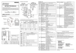
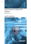
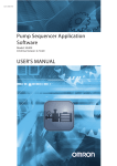
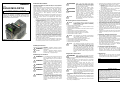
PNSPO!
Model
3G3AX-MX2-DRT-E
INSTRUCTION SHEET
Thank you for purchasing an OMRON product. Read this
thoroughly and familiarize yourself with the functions and
characteristics of the product before using it. Keep this
instruction sheet for future reference.
OMRON Corporation
© 2010 OMRON Europe BV All rights reserved
1111953-5A
WARNING
■ General Precautions
The user must operate the product according to the performance
specifications described in this instruction sheet and in the operation
manual of the inverter.
Before using the product under conditions which are not described in the
inverter manual or applying the product to nuclear control systems,
railroad systems, aviation systems, vehicles, combustion systems,
medical equipment, amusement machines, safety equipment, and other
systems, machines, and equipment that may have a serious influence on
lives and property if used improperly, consult your OMRON
representative.
Make sure that the ratings and performance characteristics of the product
are sufficient for the systems, machines, and equipment, and be sure to
provide the systems, machines, and equipment with double safety
mechanisms.
•
The MX2-A□ inverter with a mounted 3G3AX-MX2-DRT-E option
board is a general purpose product combination. It is a system
component and is used in conjunction with other items of industrial
equipment such as PLCs.
•
A detailed system analysis and job safety analysis should be
performed by the system designer or system integrator before
including the inverter option board combination in any new or
existing system. Consult your OMRON representative for
application specific system integration information if required.
•
The product will be used to control an adjustable speed drive
connected to high voltage sources and rotating machinery that is
inherently dangerous if not operated safely. Interlock all energy
sources, hazardous locations, and guards in order to restrict the
exposure of personnel to hazards. The adjustable speed drive may
start the motor without warning. Signs on the equipment installation
must be posted to this effect. A familiarity with auto-restart settings
is a requirement when controlling adjustable speed drives. Failure
of external or ancillary components may cause intermittent system
operation, i.e., the system may start the motor without warning or
may not stop on command. Improperly designed or improperly
installed system interlocks and permissives may render a motor
unable to start or stop on command.
•
This Instruction Sheet does not contain illustrations of the product
with protective covers removed from the MX2-A□ inverter. Make
sure that these protective covers are on the inverter before use.
WARNING
WARNING
Caution
■ Operating Environment Precautions
Caution
•
•
•
•
Do not operate the MX2-A□ inverter with a mounted
3G3AX-MX2-DRT-E option board in the following
locations (doing so may result in malfunction,
electric shock or burning):
Locations subject to direct sunlight
Locations subject to temperatures or humidity outside the range
specified in the specifications
Locations subject to condensation as the result of severe changes in
temperature
Locations subject to corrosive or flammable gases
Locations subject to dust (especially iron dust) or salts
Locations subject to exposure to water, oil, or chemicals
Locations subject to shock or vibration
•
•
•
•
Take appropriate and sufficient countermeasures
when installing systems in the following locations
(doing so may result in malfunction):
Locations subject to static electricity or other forms of noise
Locations subject to strong electromagnetic fields
Locations subject to possible exposure to radioactivity
Locations close to power supplies
•
•
•
Caution
Caution
■ Safety Precautions
Definition of Precautionary Information
a potentially hazardous situation
WARNING Indicates
which. If not avoided, could result in death or
serious injury.
Indicates a potentially hazardous situation,
Caution
which, if not avoided, may result in minor or
moderate injury, or property damage.
WARNING
WARNING
WARNING
WARNING
WARNING
Do not attempt to take an option board apart or
touch any internal parts while the power is
being supplied. Doing so may result in electric
shock.
Do not touch the conductive parts such as the
internal PCB or connector while power is being
supplied. Doing so may result in electrical
shock.
Do not attempt to disassemble, repair, or
modify an option board. Any attempt to do so
may result in malfunction, fire, or electric shock.
Wiring, maintenance or inspection must be
performed by authorized personnel. Not doing
so may result in electrical shock or fire.
Turn OFF the power supply before performing
wiring, maintenance or inspection. Wait for the
time specified on the Inverter front cover for the
capacitors to discharge. Not doing so may
result in electrical shock.
Provide safety measures in external circuits,
i.e. not in the option board. This ensures safety
in the system if an abnormality occurs due to
malfunction of the option board or another
external factor affecting the option board
operation. Not doing so may result in serious
accidents.
The operating environment of the MX2-A□ inverter
with a mounted 3G3AX-MX2-DRT-E option board
can have a large effect on the longevity and
reliability of the system. Improper operating
environments can lead to malfunction, failure, and
other unforeseeable problems with the system.
Make sure that the operating environment is within
the specified conditions at installation and remains
within the specified conditions during the life of the
system.
■ Application Precautions
■ Warnings and Cautions
WARNING
Refer to the section “MX2 Inverter Safety
(ISO 13849-1)” for details if the safety
measures mentioned in the previous warning
are to be ensured using the Gate Suppress
function of the MX2-A□ inverter.
Emergency stop circuits, interlock circuits,
limit circuits, and similar safety measures
must be provided in external control circuits.
Fail-safe measures must be taken by the
customer to ensure safety in the event of
incorrect, missing, or abnormal signals
caused by broken signal lines, momentary
power interruptions, or other causes. Not
doing so may result in serious accidents.
Do not touch the inverter during power-on,
and immediately after power-off. Hot surface
may cause injury.
Failure to abide by the following precautions
could lead to serious or possibly fatal injury.
Always read these precautions.
Always connect the grounding cable to one of the ground terminals of
the MX2-A□ inverter.
Check any user program in the system that acts as a DeviceNet
master before actually running it. Not checking the program may
result in unexpected operation.
A revision AAAA MX2-A□ inverter allows the motor to run
immediately if a trip condition is reset, and at the same time, a run
command is active via DeviceNet. For safe operation clear the run
command via DeviceNet as soon as a trip condition is detected.
Check the MX2-A□ inverter revision using the section “MX2 Inverter
Support” on the next page.
WARNING
•
•
•
Failure to abide by the following precautions could
lead to faulty operation of the option board or the
inverter, or could damage either of the two. Always
read these precautions.
Install external breakers and take other safety measures against
short-circuits in external wiring. Not observing this may result in
burning.
Be sure that all the cable connector screws are tightened to the
torque specified in the relevant manuals. Incorrect tightening torque
may result in malfunction.
Do not allow metal clippings to enter either option board or inverter
when wiring or installing the unit.
Caution
•
•
•
•
•
•
•
•
•
•
•
•
•
Follow the network configuration and wiring instructions provided in
the “DeviceNet Operation Manual” (Cat. No. W267).
o Wire the DeviceNet cables correctly. Incorrect wiring may result
in burning.
o Wire the DeviceNet connectors correctly. Incorrect wiring may
result in burning.
o Apply termination at both ends of a DeviceNet cable segment.
Do not apply termination anywhere else.
Be sure that the option board is mounted correctly. Improper
mounting may result in malfunction.
Disconnect the grounding cable when performing withstand voltage
tests. Not disconnecting the grounding cable may result in burning.
Check the inverter settings for proper inverter behaviour before
actually operating the inverter remotely via the DeviceNet network.
Check the network related inverter settings regarding DeviceNet
node address and DeviceNet remote I/O allocation. Not doing so
may result in unexpected operation.
Check the inverter’s EzSQ program and its interaction with the
DeviceNet master before actually running it on the inverter. Not
checking the program may result in unexpected operation.
When replacing an inverter be sure that all inverter settings of the
inverter being replaced are restored to the replacement.
Restoring parameters stored in the remote operator also restores the
DeviceNet node address. Always check the node address and other
network related inverter settings after restore.
Confirm that no adverse effect will occur at the moment the
DeviceNet master stops communicating with the inverter or at the
moment the DeviceNet master has not yet started communicating to
the inverter.
Confirm that no adverse effect will occur in the inverter before forcesetting/force-resetting any bit in the system that acts as a DeviceNet
master.
■ Handling, Storage and Disposal
•
•
•
Before touching the option board or inverter, be sure to first touch a
grounded metallic object in order to discharge any static built-up. Not
doing so may result in malfunction or damage.
When transporting or storing the option board, cover the PCBs with
electrically conductive materials to prevent electronic components
from being damaged by static electricity. Also keep the product within
the specified storage temperature range.
Never dispose electrical components by incineration. Contact your
state environmental agency for details on disposal of electrical
components and packaging in your area.
■ Compliance with EC Directives
•
This product complies with EC Directives when mounted on an
MX2-A□ inverter and having connected the grounding cable. For
grounding, cable selection, and any other conditions for EMC
compliance, refer to the MX2 User’s Manual for installation.
■ References
Please be sure to read the related user manuals to use the
3G3AX-MX2-DRT-E option board safely and properly. Be sure you
are using the most current version of the manual.
Name
MX2 User’s Manual
DeviceNet Operation Manual
Cat No.
I570-E2-01
W267
SUITABILITY FOR USE
OMRON shall not be responsible for conformity with any standards, codes,
or regulations that apply to the combination of products in the customer’s
application or use of the products.
Take all necessary steps to determine the suitability of the product for the
systems, machines, and equipment with which it will be used.
Please know and observe all prohibitions of use applicable to the products.
NEVER USE THE PRODUCTS FOR AN APPLICATION INVOLVING
SERIOUS RISK TO LIFE OR PROPERTY WITHOUT ENSURING THAT
THE SYSTEM AS A WHOLE HAS BEEN DESIGNED TO ADDRESS THE
RISKS, AND THAT THE OMRON PRODUCTS ARE PROPERLY RATED
AND INSTALLED FOR THE INTENDED USE WITHIN THE OVERALL
EQUIPMENT OR SYSTEM.
See also product catalogs for Warranty and Limitations of Liability.
Option Board Description
EDS File and CX-Integrator
The 3G3AX-MX2-DRT-E is an option board that can be attached to an
MX2-A□ series inverter. The 3G3AX-MX2-DRT-E allows controlling,
monitoring and parameterization of the inverter via a DeviceNet network.
The application in the system that acts as a DeviceNet master is
responsible for correct behaviour of the system. The 3G3AX-MX2-DRT-E
is a gateway that passes the communicated register values from the
DeviceNet network to the inverter and vice versa.
OMRON provides a series of EDS files for the 3G3AX-MX2-DRT-E option
board via the OMRON website. For each of the MX2 inverter type there is
a unique EDS file, which is named:
MX2 Inverter Support
MX2-A□ inverter version can be read from the inverter type label. Please
check the revision characters have been placed in the bottom-right corner
of the type label. The revision characters have a layout as
shown in the figure, with the asterisks replaced by a revision
character. If the inverter does not contain such a revision label, this version does not support the 3G3AX-MX2-DRT-E.
MX2 Inverter Safety (ISO 13849-1)
MX2-A□ inverters provide the Gate Suppress function to perform a safe
stop according to the EN60204-1, stop category 0. The option board has
been designed not to interfere with this safety function.
CX-Integrator is the configuration program for OMRON DeviceNet
masters. Start CX-Integrator and select the Tools/EDS File/Install menu
item. Select the EDS file(s) to start using the 3G3AX-MX2-DRT-E together
with OMRON DeviceNet masters.
Supported Modules and I/O Register Layout
The 3G3AX-MX2-DRT-E supports the modules as listed in the EDS file.
The modules can be selected as pair by using the default connection /
fixed allocation mechanism of the master or by user allocation. The table
below shows which modules can be selected given the setting in P046:
Default Connection Path.
P046
Description
Output
assem
bly
Input
assem
bly
0
1
2
3
4
5
Basic Speed IO
Extended Speed IO (default)
Extended Speed and Torque Control
Special IO
Extended Control IO
Extended Control IO and Multi function IO
monitor
Flexible format
Extended Speed and Acceleration Control
20
21
123
100
101
101
70
71
173
150
151
153
139
110
159
111
The DeviceNet master can be the source of either frequency reference or
run command. The selected modules influences the required source
selection. See the section below about Option Board Related Inverter
Parameters.
Follow the next steps to install a 3G3AX-MX2-DRT-E on an MX2-A□
series inverter:
1.
2.
Power down the inverter
Loosen the screw of the option board cover, remove the cover and
put the cover aside
3. For inverters up to 4.0 kW only: loosen the screws of the terminal
block cover and remove the cover to enable access to the chassis
ground terminal screws
4. Connect the grounding cable to the chassis ground of the inverter
(located on the cooling fin)
5. If removed, mount the terminal cover again and tighten the screw(s)
6. Push the 3G3AX-MX2-DRT-E option board into the previous location
of the option board cover until it clicks into place
7. Tighten the screw of the option board (do not over-tighten).
8. Select the right warning language from the warning label sheet and
replace the English warning if appropriate.
9. Power up the inverter and select
•
the node number via inverter parameter P192
•
the default connection path P046
For other option board related inverter parameters see below
10. Power down the inverter before attaching the DeviceNet connector
In case the DeviceNet master is configured using the user allocation, only
the pairs as specified for the default connection paths are supported.
P033
Torque Command Source
P036
Torque Bias Mode
Indicator
Color
Status
Meaning
MS
(Module
Status)
Green
Red
Lit
Lit
---
Flashing
Not lit
Green
Lit
Normal operating status
Unit hardware error
Unsupported inverter version.
DeviceNet power supply is OFF.
Power is not supplied to the Slave
Unit. The Unit is being reset.
Network is operating normally
(communications established)
Network is operating normally, but
communications have not been
established.
Communications error. Unit has
detected that network communication
is not possible. Bus Off error.
Node address duplication.
Communications time-out.
Checking for node address duplication
at the Master.
Power supply is OFF.
NS
(Network
Status)
Flashing
Red
---
Lit
Flashing
Not lit
Various inverter parameters influence the behaviour of the option board.
The table below shows these parameters. Please note that most
parameter changes require a power cycle of the inverter or a restart of the
option board.
DeviceNet Network Related Parameters
Par
Description
Setting
P045
P048
For option board as source:
Set to 4 for P046 is not 6
Set to 3 for P046 is 6 (Flexible
format)
For option board as source:
Set to 6 for P046 is not 6
Set to 3 for P046 is 6 (Flexible
format)
For option board as source:
Set to 5 for P046 is not 6
Set to 0 for P046 is 6 (Flexible
format)
Set to 63 for option board as source
Set to 63 for option board as source
Set to 16 for option board as source
DeviceNet Node Address
Communication watchdog
timer while running.
Note: additional to
Devicenet inactivity timer.
Action on Network Error
Action on Network Idle
Mode
0 to 63 (default: 63)
0 to 9999 in 0.01 s units. Set 0 to
disable.
Action is defined in P045.
n to
n+3
n+4
See instance ID 151.
-
MI7
-
MI6
-
MI5
-
MI4
-
MI3
-
MI2
-
MI1
-
Output bits
Name
Description
FWD
REV
RST
Forward/Stop
Reverse/Stop
Fault Reset
Option Board Behaviour Related Parameters
Par
Description
Setting
REF
NetRef
C102
P160P169
P170P179
CTR
NetCtrl
FFL
CI3 to
CI7
CO1,
CO2,
CR
Force Fault
Control
/Override Input
Set (Relay)
Output
0: Stop 1: Forward
0: Stop 2: Reverse
Reset Fault/Trip condition on transition from
0 to 1
Speed reference input is set.
0: Setting of A002 1: DeviceNet reference
Run command input is set.
0: Setting of A001 1: DeviceNet reference
Force external fault/trip from network
0: Reset 1: Set override for Multi Function
input 3 to 7
0: Reset 1: Set Multi Function output 1 to 2 or
Relay Output (CR)
C021
C022
C028
Output Terminal 11 Source
Output Terminal 12 Source
Analog Output AM Source
Reset Mode Selection
Output Register 1 to 10
contents
Input Register 1 to 10
contents
Set to 3 for resetting trip only
Modbus register mapped into
flexible output word 1 to 10
Modbus register mapped into
flexible input word 1 to 10
IO Assembly Object Allocation
The following table shows the I/O allocation for the main assemblies.
Word
Bit Allocation
7
6
5
4
3
2
1
0
15
14
13
12
11
10
9
8
Instance ID 20: Basic Speed Control Output
n
n+1
RST
Rotational Speed Reference (default [0.01 Hz])
Rotational Speed Reference
-
FWD
-
n+1
DFR
Rotational Speed Monitor (default [0.01 Hz])
Rotational Speed Monitor
n
n+1
REF
CTR
RST
Rotational Speed Reference (default [0.01 Hz])
Rotational Speed Reference
n+1
ARF
RFN
CFN
RDY
DRR
DFR
Drive Status (see below)
Rotational Speed Monitor (default [0.01 Hz])
Rotational Speed Monitor
Bit
Name
Description
FLT
WR
DFR
0: Normal 1: Fault/Trip
0: Normal 1: Warning
0: Stop/reverse 1: During forward run
CFN
Fault
Warning
During
forward run
During
reverse run
During zero
speed
Inverter
ready
Ctrl from Net
RFN
Ref from Net
ARF
MI1 to
MI7
MO1,
MO2,
MR
At reference
Monitor
inputs 1 to 7
Monitor
(Relay)
outputs
DZS
-
FLT
-
REV
-
FWD
-
Instance ID 71: Extended Speed Control Input
n
Input bits
DRR
Instance ID 70: Basic Speed Control Input
n
WR
FLT
RDY
0: Stop/forward 1: During reverse run
0: Non-zero speed 1: During zero speed.
0: Inverter not ready 1: Inverter ready
Run command input selection
0: Setting of A002 1: DeviceNet controlled
Speed reference input selection
0: Setting of A001 1: DeviceNet reference
0: Accel/decel phase 1: At reference
0: OFF 1: ON
0: OFF 1: ON
Drive Status (for instance ID 71 and 173)
Instance ID 123: Extended Speed and Torque Control Output
Value
Description
Value
Description
n/n+1
n+2
1
2
3
4
Startup
Not ready
Ready
Enabled
5
6
7
Stopping
Fault/Trip Stop
Faulted/Tripped
See instance ID 21
Torque Reference [1 %]
Torque Reference
Instance ID 173: Extended Speed and Torque Control Input
n/n+1
n+2
See instance ID 71
Torque actual [1 %]
Torque actual
General Specifications
Instance ID 101: Extended Control Output
n+1
n+2
n+3
CI7
CI6
CI5
CI4
CI3
CO2
CO1
CR
Rotational Speed Reference (default [0.01 Hz])
Rotational Speed Reference
Torque Reference [1 %]
Torque Reference
Torque Compensation Bias [1 %]
Torque Compensation Bias
REV
RST
FWD
FFL
DZS
-
DFR
-
n
n+1
n+3
FLT
WR
RDY
ARF
DRR
MO1
MR
CFN
MO2
Rotational Speed Monitor (default [0.01 Hz])
Rotational Speed Monitor
Torque actual [1 %]
Torque actual
Output current monitor [0.1 A]
Output current monitor
Item
Specifications
DeviceNet Specification
DeviceNet Profile
Automatic baud rate detection
Ambient operating temperature
Ambient operating humidity
Storage temperature
Weight
Designed for conformance.
AC Drive (0x02)
Yes
See MX2 inverter User’s Manual
See MX2 inverter User’s Manual
-20 ºC to 65 ºC
170g
PNSPO!
Instance ID 151: Extended Control Input
n+2
Set to 0 for inverter trip (default)
Set to 1 for deceleration and trip
Set to 2 for no action
Set to 3 for stop due to free-run
Set to 4 for deceleration and stop
Bit Allocation
7
6
5
4
3
2
1
0
15
14
13
12
11
10
9
8
Instance ID 153: Extended Control Input + Multi Function Input
Bit
n
Option Board Related Inverter Parameters
P192
P044
Word
Setting
Instance ID 21: Extended Speed Control Output
LED Indicators
DeviceNet Connector and Wiring
The 3G3AX-MX2-DRT-E option board is supplied with a multi-drop
DeviceNet connector with color coded lines. Connect the DeviceNet
network’s communications cable to the DeviceNet communications
connector.
Motor 1 Frequency Source
Motor 1 Run Command
Source
□ indicates the specific inverter type, such as A4150 or AB004_A2004.
Use these EDS files in the DeviceNet master configuration program used
to configure your DeviceNet master.
6
7
Installation Procedure
A001
A002
3G3AX-MX2-DRT-□-E.eds
External Dimensions
The drawings below specify the external dimensions of the option board.
Source Selection Parameters
Par
Description
OMRON EUROPE BV
Wegalaan 67-69, NL- 2132 JD Hoofddorp
The Netherlands
Tel: (31) 23-5681300 / Fax: (31) 23-5681388
Note: Specification is subject to change without notice