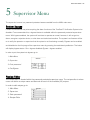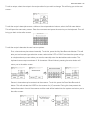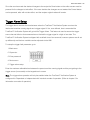
1
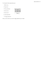
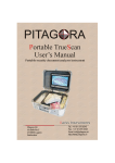
Table of Contents I ii
TrueScan™ Verification System - Operations Manual
© Copyright 2007 by Buist Electric, Inc., Byron Center, Michigan
CONTACT INFORMATION: For questions or troubleshooting, please call us toll free:
Monday - Friday, 8:00am - 5:00pm, Eastern Standard Time 1-800-878-1494 from anywhere in the U.S. or Canada
Or visit us on the web: www.buistautomation.com
Limited Warranty
Buist Electric, Inc. (the “Company”) warrants that (a) its Bar Code Scanning System (the “Equipment”) will perform substantially in accordance with
the accompanying written materials for a period of ninety (90) days from the date of receipt and (b) that the Equipment will be free from defects in
materials and workmanship under normal use and service for a period of one (1) year. IN NO EVENT SHALL THE COMPANY BE LIABLE
FOR INDIRECT, SPECIAL, OR CONSEQUENTIAL DAMAGES OF ANY NATURE WHATSOEVER. This Limited Warranty is void if
failure of the Equipment has resulted from accident, abuse, or misapplication. This Limited Warranty gives you specific legal rights. You may have other
rights which may vary from jurisdiction to jurisdiction.
Exclusive Remedy
In the event a defect in materials and workmanship under normal use and service is discovered for a period of one (1) year from the date of receipt, the
Company’s and its suppliers’ entire liability and your exclusive remedy shall be, at the Company’s option, either (a) return of the price paid for the
Equipment, or (b) repair or replacement of the Equipment that does not meet this Limited Warranty. Any replacement Equipment will be warranted for
the remainder of the original, Limited Warranty period or thirty (30) days, whichever is longer.
DISCLAIMER OF WARRANTIES
NO OTHER WARRANTIES. TO THE MAXIMUM EXTENT PERMITTED BY LAW, THE COMPANY AND ITS SUPPLIERS
DISCLAIM ALL OTHER WARRANTIES, EITHER EXPRESS OR IMPLIED, INCLUDING, BUT NOT LIMITED TO IMPLIED
WARRANTIES OF MERCHANTABILITY AND IMPLIED WARRANTIES OF FITNESS FOR A PARTICULAR PURPOSE, WITH
REGARD TO THE EQUIPMENT AND ANY RELATED OR ACCOMPANYING WRITTEN MATERIALS.
NO LIABILITY FOR DAMAGES. TO THE MAXIMUM EXTENT PERMITTED BY LAW, IN NO EVENT SHALL THE COMPANY
OR ITS SUPPLIERS BE LIABLE FOR ANY DAMAGES WHATSO-EVER (INCLUDING WITHOUT LIMITATION, SPECIAL,
INCIDENTAL, CONSEQUENTIAL, OR INDIRECT DAMAGES FOR PERSONAL INJURY, LOSS OF BUSINESS PROFITS,
BUSINESS INTER-RUPTION, LOSS OF BUSINESS INFORMATION, OR ANY OTHER PECUNIARY LOSS) ARISING OUT OF
THE USE OF OR INABILITY TO USE THIS PRODUCT, EVEN IF THE COMPANY HAS BEEN ADVISED OF THE POSSIBILITY
OF SUCH DAMAGES. IN ANY CASE, THE COMPANY’S AND ITS SUPPLIERS’ ENTIRE LIABILITY UNDER ANY PROVISION
OF THIS AGREEMENT SHALL BE LIMITED TO THE AMOUNT ACTUALLY PAID BY YOU FOR THE EQUIPMENT. BECAUSE
SOME JURISDICTIONS DO NOT ALLOW THE EXCLUSION OR LIMITATION OF LIABILITY FOR CON-SEQUENTIAL OR
INCIDENTAL DAMAGES, THE ABOVE LIMITATION MAY NOT APPLY TO YOU.
10 9 8 7 6 5 4 3 2 1
Table of Contents I iii
1 Safety
1
2 Product Description ……………………………….……...2
3 Operating Principles
Human Machine Interface (HMI)……………...3-5
Screen Backlight Colors………………3
Language Selection……………………3
Main Menu………………………………3
Screen Map.........................................4
Push Button Operation………………...4
Setting Values…………………………..4
Passwords...........................................5
Home Screen…………………………...5
Recipes…………………………………………..5
Mode of Operation……………………………...5-6
Dependent……………………………….6
Independent with Interlocks.................6
Independent……………………………..6
Sleep Mode……………………………………...7
Alarms…………………………………………….7
Beacon……………………………………………7
Trigger Signal……………………………….……7
(Optional) Rejection Device…………………….8
4 Installation
Wiring……………………………………………...9-10
Mounting…………………………………………..11
5 Supervisor Menu
System Bypass……………………………………12
Recipe Editor………………………………………12-14
Trigger Alarm Setup……………………………….14
Sleep Mode Setup………………………………...15
Mode Selection…………………………………….15-16
Data Collection Enable/Disable………………….16
Data Collection Reset……………………………..17
Table of Contents I iv
Password Setup……………………………………17-19
6 Reject Configuration
Reject Enable/Disable……………………………...20
Reject Mode of Operation………………………….20-21
On-Delay Time……………………………………….21
Output Duration……………………………………...21
Offset Count………………………………………….22
7 Recipe Selection
23
8 Information Menu
Contact Information………………………………….24
Active Recipe………………………………………...24
System Status………………………………………...25
Input String Monitor………………………………….25
Average Scan Quality per 100 Scans……………..25
Data Collection……………………………………….26
9 Communication
27
10 Leuze Electronic BCL22 Interface
28
Buist Automation I 1
1 Safety
Observe the following notices to ensure personal safety or to prevent accidents. Read the user’s manual
thoroughly before use.
Warning: The Leuze Electronic BCL22 scanner uses a red laser of class 2 laser light acc. to EN 60825-1
(2003/10).
Never look directly into the laser beam; it could cause damage to the retina of the eye.
When mounting the scanner head, avoid pointing it at reflective surfaces. Never orientate the scanner so
that the laser light can be directed into someone’s eye.
Follow the laser safety regulations according to DIN EN 608285-1 in their most current version.
Changes to the TrueScan™ Verification System except those described in this manual, are not permitted.
Any unauthorized changes will void any warranty, could cause damage to the system, and could create a
hazard to others.
Dangerous voltages are present in the control cabinet. Service should be performed by qualified persons
only in compliance with state and local codes.
This system is intended for use with packaging and labeling machines. This system is not intended or
authorized to be used in explosive atmospheres or for medical purposes.
Refer to the Leuze Electronic Barcode reader BCL 21/22 Technical manual for further safety concerns.
Buist Automation I 2
2 Product Description
The TrueScan™ Verification System (figure 2.1) is a barcode comparison system designed to analyze UPC
and EAN barcodes against pre-programmed recipes.
Figure 2.1
TrueScan™ Verification System Buist automation
Buist Automation I 3
3 Operating Principles
This section is intended to improve the user’s understanding of the TrueScan™ Verification System by giving
a descriptive narrative of the system’s key features.
Human Machine Interface (HMI)
The TrueScan™ Verification System as an HMI to allow the user system configuration and monitoring. The
HMI is typically installed in the front of the system’s main enclosure, but may be installed in a remote
enclosure.
Screen Backlight Colors
The HMI has (3) color LED backlights giving users’ system status at a glance. The display screen’s (3)
colors are; white for non-password protected areas, pink for password protected configuration areas, and
red for system alarms.
Language Selection
When the system powers up the HMI’s start-up screen is displayed. This screen displays the customer’s
name or logo as well as language selection buttons. To move past this screen the user must select one of
the available languages. All screen text will then be displayed in the selected language. To return to the
language selection screen power must be cycled to the TrueScan™ Verification System.
Main Menu
The main menu is the gateway to all areas in the HMI. From the main menu the user can access the
Supervisors Menu, Reject Configuration Menu, Recipe Selection Menu, Information Menu, and Home
Screen.
Buist Automation I 4
Screen Map
Push Button Operation
Most of the HMI’s pushbuttons are momentary and navigate the user through the menus. There are however,
some pushbuttons which are maintained. These maintained pushbuttons are used to select and deselect
various settings i.e.… Bypass Enable, Reject Enable, Mode of Operation, Recipe Select …etc. These
maintained pushbuttons will indicate status with highlighted text if selected.
Setting Values
The user will often encounter keyboard screens requiring data entry. It’s important to take note; the keyboard
is not enabled until the user first selects the data window. Once the data window is selected the user will see
a blinking courser and the keyboard will allow data entry. When finished entering data, select the keyboards
enter button to send the new value to the system.
Press data window to
Press enter to send
Buist Automation I 5
Passwords
The TrueScan™ Verification System has (2) password protected menus, Supervisor Menu and Reject
Configuration Menu. Both of these menus contain system configuration settings which typically should only
be accessed by an administrator. When selecting one of these areas from the Main Menu the user is
presented with a keyboard screen to enter a password. If the correct password is entered access is granted.
While in a password protected area if the system does not see HMI activity for 60 seconds the user will
automatically be returned to the main menu. In addition to the password protected menus, the Misread
Alarm reset is also password protected. If the system samples a different barcode than what’s defined in the
active recipe, the system will go into a Misread Alarm. This alarm may only be reset with a password. This
feature is intended to ensure a manager is aware of any possible quality issues.
Note: By default all passwords are 1234.
Home Screen
The Home screen is accessed from the HMI’s main menu. This screen should be the screen a user will
typically interface with. The screen provides the user feedback such as, each sample’s scan quality, active
recipe, and system status… i.e. running, stopped, bypass.
Recipes
The TrueScan™ Verification System allows up to (50) recipes to be created, stored, and selected. Each
recipe allows the user, through the password protected Supervisor’s Menu, to create a unique name and
barcode number. Created recipes can be selected by the user through the non-password protected Recipe
Selector menu. When selected, the recipe will immediately be loaded to the active recipe and any barcodes
being sampled will begin being compared to the new recipe.
Mode of Operation
The TrueScan™ Verification System has (3) different modes of operation for various customer applications;
dependent, independent with interlocks, and independent. These modes allow the customer to select
whether the TrueScan™ Verification System will function interlocked with another machine or as an
independent unit. Depending on the selected mode of operation, different hardwired interlocks are required.
Having an understanding of the different modes of operation is important for a correct installation.
Buist Automation I 6
Dependent: The system is interlocked with another machine and only runs if commanded by that
machine. “Trigger” signals are only accepted by the system if the interlocked machine running signal
is being received. The interlocked machine run enable signal should be used to shut down an
interlocked machine in the event of a system alarm. If a, customer supplied, optional rejection device
is interlocked with the system; sampled barcodes which fail the comparison test will be rejected. The
system utilizes interlock signals from other equipment, therefore; all system options will be enabled.
This mode of operation is typically used in applications where the barcodes being sampled are
printed on a continuous web. This mode allows the user to determine when during a process the
scanner should be running. In some applications having the scanner running during setup or other
manual functions can result in nuisance alarms. By using the interlocked machine running signal, the
user can configure when the system should be running and eliminate these nuisances.
Independent with Interlocks: The system is interlocked with another machine, and is always running. The
interlocked machine running signal is still used, but only for the No Trigger Alarm function. The
interlocked machine enable signal should be used to shut down an interlocked machine in the event
of a system alarm. If a, customer supplied, optional rejection device is interlocked with the system;
sampled barcodes which fail the comparison test will be rejected. The system utilizes interlock
signals from other equipment, therefore; all system options will be enabled. This mode of operation is
typically used in applications where the system is mounted downstream of the interlocked machine
and the user wants to ensure any product triggering the scanner is sampled regardless of the
interlocked machines state. This mode of operation utilizes machine interlocks to ensure trigger
sensor integrity and shutdown a machine in the event of an alarm.
Independent: The system operates completely independent of any other production equipment. The
system is always running, so for every “trigger” signal the system will sample a barcode against the
active recipe. The system does not utilize any interlock signals from other equipment, therefore; both
Sleep mode and No Trigger Alarm will be disabled. If a, customer supplied, optional rejection device
is interlocked with the system; upon getting an alarm the reject output will remain energized until the
alarm is reset. A typical application for this mode of operation would be mounted along a
continuously running conveyor. Where the user wants to ensure the system’s always running and
samples product regardless of how it got on the conveyor.
Note: By default the system is set for Independent operation.
Buist Automation I 7
Sleep Mode
The Leuze Electronic BCL22 scanner has an internal motor for rotating mirrors. In an effort to extend the life
of the scanner’s motor the system has a sleep mode. If the system sits idle in Dependent mode for a user
defined amount of time the system will turn off the scanner’s internal motor. When in sleep mode the scanner
and interlocked machine will be disabled and the HMI will indicate the system’s sleep state. The user will
need to “wake” the scanner, via the HMI, to restart the scanner’s internal motor. (This function is dependent
on the selected mode of operation.)
Alarms
The system has four different possible alarms:
1. Misread Alarm – The sampled barcode does not match the active recipe’s defined barcode.
2. No read Alarm – The scanner was unable to decode five consecutive barcodes.
3. No Trigger Alarm – The system failed to receive a trigger signal within the user defined allotted time. (This
function is dependent on the selected mode of operation.)
Comm Loss Alarm – The system is not receiving valid data strings from the scanner.
Beacon
The system’s multi-colored beacon is a visual indication of the system’s status. Green indicates the system is
OK and running. Amber indicates the system is ready but not running. Red indicates the system is in alarm,
sleeping, or bypass. If the user sees a red beacon corrective action, if desired, should be taken.
Trigger Signal
An external trigger signal (customer provided) is required to activate the scanner at the time a barcode is to
be sampled. Upon receiving a trigger signal the scanner’s laser will activate, the barcode will be decoded,
and the system will compare it with the active recipe defined barcode. If the barcode passes the comparison
test the system will display the quality of the scan (0-100%) and be ready for the next trigger; however, if the
barcode fails the comparison test the system will go into a Misread Alarm. Lastly, if the system is unable to
decode the barcode the system will display 0% scan quality and wait for the next trigger.
Understanding the trigger signal is important for optimal performance. By default the TrueScan™ Verification
System is configured to activate on the falling edge of a 24VDC signal. The scanner will remain active until a
barcode is decoded, the rising edge of the next 24VDC trigger signal, or the maximum activation time of 10
seconds has elapsed.
Buist Automation I 8
If necessary, the system can be configured for scanner activation on the rising edge of a trigger signal. For
this to be possible the user will need to make a minor wiring change. Refer to page SXXXXX-011 of the
electrical schematics for details.
(Optional) Rejection Device
The system does provide a normally open dry contact for the user to connect a customer provided rejection
device. The system will reject any barcode that cannot be decoded or does not pass the comparison test.
This rejection output will need to be enabled and configured before being ready to use. (Refer to chapter 6
in the user manual for more details.)
Buist Automation I 9
4 Installation
Wiring
The TrueScan™ Verification System should be installed by a qualified person in accordance with local
codes.
The TrueScan™ Verification System is shipped UL listed. In order to maintain this rating, and also for easy
installation or replacement, the TrueScan™ Verification System is shipped with cord and plug connections.
There is no need to drill any entry holes in the enclosure.
The Leuze Electronic BCL 22 scanner head plugs into the standard 15 pin sub D connector on the bottom
of the TrueScan™ Verification System enclosure. The Leuze BCL 22 scanner head comes with a 3m cable
on it. Do not attempt to lengthen or shorten the cable by cutting it or replacing it as this will void any
warranty. For pin-out designations and other Leuze scanner head technical data, refer to the Leuze
Electronic Barcode Reader BCL 21/22 Technical Manual.
PJ1000-2: A 12 foot, three conductor female cord supplied with the system. This must be connected to a
customer supplied 120vac, maximum 15amp, 1ph, 60Hz power source and plugged into its male mate on
the bottom of the TrueScan™ Verification System. (See figure 4.1 wiring diagram)
PJ1202-2: A 12 foot, six conductor female cord supplied with the system. This cable contains the
connections for the optional rejection device and interlocked machine run enable contacts. These signals
may be required depending on the selected mode of operation. (Refer to chapter 6 Reject Configuration
and chapter 5 mode of operation). The flying lead end of the cable should be connected to the interlocked
equipment. The female connector end of the cable plugs into its male mate PJ1202-1on the bottom of the
TrueScan™ Verification System. (See figure 4.1 wiring diagram)
PJ1216-2: A 12 foot, six conductor male cord supplied with the system. This cable contains the connections
for the customer supplied trigger sensor and optional interlocked machine running signal. The trigger signal
must be sourced from the TrueScan™ Verification System’s 24VDC power supply. The optional interlocked
machine running signal may be required depending on the selected mode of operation. (Refer to Chapter 5
Mode of Operation). The flying lead end of the cable should be connected to the trigger source and any
interlocked equipment. The female connector end of the cable plugs into its female mate PJ1216-1on the
bottom of the TrueScan™ Verification System. (See figure 4.1 wiring diagram)
Buist Automation I 10
The trigger signal should be generated from a (customer supplied) solid state source which must provide a
trigger for each barcode to be read.
Buist Automation I 11
Mounting
Enclosure
The TrueScan™ Verification System enclosure should be mounted in a location where the user can easily
see and access the HMI touch screen on the front of the unit and within reach of the scanner head location.
Leuze Electronic BCL22 scanner
All safety precautions outlined in chapter one “Safety” must be observed when mounting the Leuze
Electronic BCL22 scanner.
Because each application is uniquely different, it is up to the customer to provide the best means by which
to mount the scanner. The scanner bracket should be adjustable and mounted to a solid anchor point with
as little vibration as possible. The scanner head should be mounted 4 to 9 inches away from the barcode.
Positioning varies depending on the size of the barcode. For most materials, especially those with reflective
properties, the scanner head should be mounted at a 9 to 15 degree angle from perpendicular. For further
mounting instructions and warnings, refer to page 32 of the Leuze Electronic Barcode Reader BCL 21/22
Technical Manual.
Buist Automation I 12
5 Supervisor Menu
The supervisor’s menu is a password protected area accessible from the HMI’s main menu.
System Bypass
Certain circumstances may arise requiring the alarm functions of the TrueScan™ Verification System to be
disabled. To accommodate this, a bypass feature is available within the password protected supervisors
menu. With bypass enabled, the system will continue to operate as normal, however; it will not go into
alarm, energize a rejection device, or shut down an interlocked machine. The system’s red beacon will be
on to notify the operator or supervisor that the system is not functioning normally. Bypass can be enabled
and disabled on the first page of the supervisor menu by pressing the maintained pushbutton. The button
will display bypass status: Run = bypass disabled Bypass = bypass enabled.
In order to put the system into bypass go to:
1. Main Menu
2. Supervisor
3. Enter password
4. Run/Bypass
Recipe Editor
The recipe editor is located within the password protected supervisor menu. The recipe editor is where
users can define a unique name and barcode for each of the available (50) recipes.
In order to edit recipes go to:
1. Main Menu
2. Supervisor
3. Enter password
4. Recipe Editor
Buist Automation I 13
To edit a recipe, select the recipe in the recipe editor list you wish to change. This will bring you to the next
screen…
To edit the recipe’s descriptive name, visible on the recipe selector buttons, select the Edit name button.
This will open the name entry screen. Enter the new name and press the enter key on the keyboard. This will
bring you back to the editor screen.
To edit the recipe’s barcode the user has two options:
First, a barcode may be entered manually. To do this, press the Key New Barcode # button. This will
take you to a barcode type selection screen, select either UPC or EAN. From there the system will go
to a keyboard entry screen where you need to manually enter the desired barcode number. The
keyboard can accept a maximum of 16 characters. When finished, pressing the enter button will
return you to the editor screen.
Second, a barcode may be entered via the scanner. To do this, press the Scan New Barcode #
button. This will activate the LASER on the scanner for (10) seconds. During this time present the
desired barcode in front of the scanner and the code will be loaded into the system and return you to
the editor screen.
Buist Automation I 14
Once the user has made the desired changes to the recipe the Save button on the editor screen must be
pressed for the changes to take effect. If the user decides the changes are not wanted the Cancel button
can be pressed, edits will not take effect, and the recipes original values will remain.
Trigger Alarm Setup
The trigger alarm monitors the time between when the TrueScan™ Verification System receives the
interlocked machine running signal and a trigger signal. If the, user defined, time is exceeded the
TrueScan™ Verification System will go into No Trigger Alarm. This feature is used to ensure the trigger
source has not failed or that someone has not locked the trigger signal in a high or low state. The
TrueScan™ Verification System is shipped with a default time of ten seconds, however systems are all set
up differently and the time variable can be adjusted via the HMI.
To setup the trigger fault parameter go to:
1. Main menu
2. Supervisor
3. Enter password
4. Next screen
5. Trigger alarm setup
Enter the maximum allowable time between the parent machine running signal and the part getting to the
trigger sensor (in seconds) on the keypad touch screen.
Note: The trigger alarm operation will only be enabled when the TrueScan™ Verification System is
configured for Dependent or Independent with Interlocks modes of operation. (Refer to chapter 5 for
information on modes of operation)
Buist Automation I 15
Sleep Mode Setup
Sleep mode is a standby condition the TrueScan™ Verification System enters to extend the life of the
scanner head. The default time setting for this is 3,600 seconds. If the TrueScan™ Verification System does
not receive an interlocked machine running signal for 3,600 seconds the system goes into standby and
neither the TrueScan™ Verification System nor the interlocked machine will be enabled until the TrueScan™
Verification System “wake” button is pressed.
The time setting can be adjusted by going to:
1. Main menu
2. Supervisor
3. Enter password
4. Next screen
5. Sleep setup
Enter the desired elapsed time before sleep mode in seconds on the keypad touch screen.
Note: Sleep Mode will only be enabled when the TrueScan™ Verification System is configured for
Dependent operation. (Refer to chapter 5 for information on modes of operation)
Mode Selection
The TrueScan™ Verification System has three different modes of operation Independent, Independent
with Interlocks, and Dependent. One of these three modes should accommodate most applications.
(Refer to chapter 3 for more information on modes of operation)
Independent: In this mode the TrueScan™ Verification System will act as a completely stand alone system,
not requiring any machine interlock connections. While in this mode the trigger fault and sleep function will
be disabled. If the optional rejection device is enabled, and the TrueScan™ Verification System goes into
alarm, the rejection contact will close and remain closed until the TrueScan™ Verification System alarm has
been reset.
Independent with Interlocks: In this mode the TrueScan™ Verification System utilizes interlock signals from
another machine, but unlike Dependent mode is always running regardless of the interlocks. This mode is
best suited for situations where the TrueScan™ Verification System is located on the out feed conveyor of an
interlocked machine. In this mode the trigger alarm remains functional ensuring the trigger is working. The
sleep function will be disabled.
Buist Automation I 16
Dependent: In this mode the TrueScan™ Verification System requires interlocks with another machine. The
TrueScan™ Verification System will run only when the interlock machine running signal is on and will disable
the interlocked machine, via the interlocked machine running contact, if the TrueScan™ Verification System
goes into alarm. All system functions and options are operational.
To select a mode of operation go to:
1. Main menu
2. Supervisor
3. Enter password
4. Next screen
5. Mode select
Modes of operation push buttons are maintained. The text on the push button selected will be highlighted.
Data Collection Enable/Disable
The TrueScan™ Verification System comes with a data collection system. The system will record and display
the number of triggers, trigger alarms, no reads, no read alarms, good reads, mismatches, and total percent
scan quality. These values are displayed for the user via the information menu, however; this feature must be
enabled through the supervisors menu.
In order to enable the data collection feature go to:
1. Main menu
2. Supervisor
3. Enter password
4. Next screen
5. Data setup
6. Data on/off
The data on/off selector button is a maintained pushbutton which will display whether the data collection is
disabled or enabled.
Buist Automation I 17
Data collection reset
In order to reset the data collection registers to zero go to:
1. Main menu
2. Supervisor
3. Enter password
4. Next screen
5. Data setup
6. Data reset
If the data reset button is pressed the system will ask if you are sure you want to reset the data, select yes or
no.
Note: If the registers are never reset they will count up to their maximum value and then roll over and start
from zero.
Password Setup
The supervisor’s menu, setup menu, and alarm reset passwords are shipped as 1234.
At the time of start-up these passwords should be changed from the 1234 factory default. The passwords
should be selected by the person who will be responsible for over-seeing the barcode scanner’s operation.
To change the supervisor password go to:
1. Main menu
2. Supervisor
3. Enter password
4. Next screen
5. Next screen
6. Supervisor password
When at the supervisor’s password screen, the current password will be displayed on the screen. To
change the current password, press the change password button and follow the enter commands. The
system will ask you to enter the new password twice to ensure the password you intend is entered. If the
confirmation entry matches the first entry, the new password will be accepted. If they do not match, the
Buist Automation I 18
system will give you a message saying the entries did not match and the new password will not be
accepted.
Return to the password menu screen and set up new passwords for the setup menu and the alarm reset.
To view the current setup alarm password go to:
1. Main menu
2. Supervisor
3. Enter password
4. Next screen
5. Next screen
6. Setup password
To change the setup password go to:
1. Main menu
2. Supervisor
3. Enter password
4. Next screen
5. Next screen
6. Setup password
7. Change Password
From here you can enter any new four digit password you choose.
To view the current alarm password go to:
1. Main menu
2. Supervisor
3. Enter password
4. Next screen
5. Next screen
6. Alarm password
Buist Automation I 19
To change the alarm password go to:
1. Main menu
2. Supervisor
3. Enter password
4. Next screen
5. Next screen
6. Alarm password
7. Change password
Here you can enter any new four digit password you choose.
Buist Automation I 20
6 Reject Configuration
The reject configuration menu is a password protected area containing all settings related to the use of a
customer supplied rejection device.
Reject Enable/Disable
In certain circumstances a rejection device may be required to eject a failed product from a process.
Because every application is different a rejection device is not provided with the TrueScan™ Verification
System, however; the system does offer an optional normally open output contact for the user to interlock
their rejection device. To enable the system’s optional reject output, the maintained Reject Enable/Disable
button within the password protected reject configuration menu must be pressed. The button will display the
reject output status: Enabled or Disabled...
In order to enable the system’s optional reject output go to:
1. Main Menu
2. Reject Configuration
3. Enter Password
4. Reject Disabled/Enabled
Reject Mode of Operation
There are (2) modes of operation for the system’s optional reject output depending on the application.
“Tracking Mode” where the system follows the failed product through a process to a rejection device and
“Timed Pulse Mode” where the reject output is energized based on time. The Reject Operation button will
display the selected mode of operation. (Refer to chap 5 for more information on the optional reject modes
of operation)
Buist Automation I 21
To select a mode of operation for the optional rejection device go to:
1. Main Menu
2. Reject Configuration
3. Enter Password
4. Reject Setup
5. Reject Operation “Timed Pulse”/”Tracking”
On Delay Time
If the optional reject mode of operation is configured for Timed Pulse the on delay time is the time between
detecting a failed barcode until the rejection output energizes. This setting is only available when the mode
of operation is Timed Pulse.
To set the on delay time go to:
1. Main Menu
2. Reject Configuration
3. Enter Password
4. Reject Setup
5. Next Screen
6. On-Delay Time
Output Duration
The Output Duration setting is the length of time the optional reject output remains energized.
To set the output duration go to:
1. Main Menu
2. Reject Configuration
3. Enter Password
4. Reject Setup
5. Next Screen
6. Output Duration
Buist Automation I 22
Offset Count
If the optional reject mode of operation is configured for Tracking the Offset Count time is the number of
trigger signals after a failed barcode until the rejection output energizes. This setting is only available when
the mode of operation is Tracking.
To set the offset count go to:
1. Main Menu
2. Reject Configuration
3. Enter Password
4. Reject Setup
5. Next Screen
6. Offset Count
Buist Automation I 23
7 Recipe Selection
Recipes can be selected by the user in the non-password protected recipe selection menu. (50) Configurable recipes
can be selected to be the active recipe by pressing the desired recipe button. The barcode associated with the active
recipe is the barcode each sample is compared against. The active recipe is displayed on both the Home screen and
Active Recipe screen in the Information menu. (Refer to chapter 3 for additional information on recipes)
To select a recipe go to:
1. Main Menu
2. Recipe Selection
Buist Automation I 24
8 Information Menu
The information menu is a non-password protected area accessible from the HMI’s main menu.
Contact Information
Selecting the Contact Information button in the information menu will bring the user to a screen with contact
information for Buist Automation’s technical support number. Buist Automation, the manufacturer of the
TrueScan™ Verification System, is available by phone Monday through Friday 8am – 4pm Eastern Standard
Time.
To access the contact information screen go to:
1. Main Menu
2. Information
3. Contact Information
Active Recipe
Selecting the Active Recipe button in the Information menu will bring the user to a screen which displays
which recipe is active. The descriptive name, type, and barcode number of the active recipe are shown.
To view the active recipe screen go to:
1. Main Menu
2. Information
3. Active Recipe
Buist Automation I 25
System Status
Selecting the System Status button in the Information menu will bring the user to a screen which displays the
system’s state…i.e. running, stopped, bypass… and selected mode of operation.
To view the System Status screen go to:
1. Main Menu
2. Information
3. System Status
Input String Monitor
As data strings are received from the Leuze Electronic BCL22 scanner the user can view these via the HMI.
The system will scroll through the data strings as they are received. Selecting the Input String Monitor button
in the Information menu will bring the user to a screen which displays these data strings in real time.
To view the Input Strings Monitor screen go to:
1. Main menu
2. Information
3. Input String Monitor
Average Scan Quality per 100 Scans
The TrueScan™ Verification System will calculate the average scan quality per 100 scans. This information
can be useful while aligning the Leuze Electronic scanner.
To view the Average Scan Quality per 100 Scans go to:
1. Main menu
2. Information
3. Avg. Scan Quality per 100 Scans
Buist Automation I 26
Data Collection
If enabled (Refer to Chapter 5), the TrueScan™ Verification System will collect system performance
information. Within the non-password protected Information Menu the user can view the following data:
Number of “Triggers”
Number of “Trigger Alarms”
Number of “Good Reads”
Number of “Misread Alarms”
Number of “No Reads”
Number of “No Read Alarms”
Total average scan quality
Data collection must be enabled/disabled and reset via the supervisor menu (Refer to chapter 5)
To view the collection registers go to:
1. Main menu
2. Information
3. Data Collection
Buist Automation I 27
9 Communication
Communication with the Panasonic PLC and HMI can be achieved via a standard USB port found on both
devices. The user will need to obtain Panasonic programming software FPWIN Pro for the PLC and GTWIN
for the HMI. All application program files will be provided on a CD with the TrueScan™ Verification System.
Buist Automation I 28
10 Leuze Electronic BCL22 Interface
The Leuze Electronic BCL22 scanner will be shipped with the correct parameters already programmed.
There should be no reason to go online with the scanner head. Any changes made to the parameter file may
cause the system to fail.
Communication between the scanner head and a PC is possible. Inside the TrueScan™ Verification System
enclosure there is a male/female nine pin sub D port. This port is for communicating with the scanner head
directly using a PC. A straight through 9 pin serial communication cable (Figure 10.1) will be needed as well
as the Leuze Electronic BCL Configuration Tool software, which will be included on the CD with the system.
Fig. 10.1
In order to communicate with the scanner head use the program provided on the CD. You will need to use
the program provided so the communication parameters match between the PC and the scanner. Once
connected the terminal mode will display the data strings being sent from the scanner. Parameter files can
be uploaded or downloaded using the software.
The following communication properties will need to be set in order to establish communication with the
Leuze Electronic BCL22 scanner:
Baudrate:
57600
Time out:
100ms
Data bits:
8 bit
Stop:
1 bit
Parity:
none
Caution: If the TrueScan™ Verification System is running while connected to the scanner with a PC you may
monitor the data string in the terminal mode only. Sending com-mands, uploading or downloading to the
scanner head will interrupt communication to the TrueScan™ Verification System processor. You may need
to cycle power to reinitiate com-munication.