1
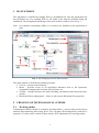
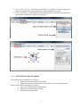
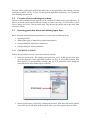
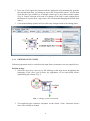
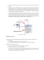
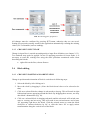
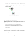
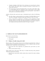
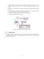
W2E COMPUTATIONAL SYSTEM MANUAL (WASTE - TO - ENERGY) 1. MAIN WINDOW The application is installed by running W2E.exe installation file; after the application has been installed, run it by opening W2E.exe file found in the directory defined during the installation. The arrangement and design of the main window could be seen in Fig. 1. Note: Java runtime environment (JRE) v1.6.x needs to be installed for the application to start. FIG. 1: The arrangement of the main window The main window is divided into following sections: Canvas – presents created scheme Menu – provides access to all application functions such as file operations, computation settings and execution, special forms, etc. Toolbar – includes shortcuts for mode switching, simulation control and some basic actions Blocks and flows editing panel – allows to edit various block and flow properties 2. CREATION OF TECHNOLOGICAL SCHEME 2.1 Working modes Technological scheme (model) is created by inserting blocks (= process units) on the canvas and then interconnecting them using flows. User can then edit existing block’s and flow’s properties. To allow easier control of these actions, W2E implements two working modes: 1 1. Insert mode (Fig. 2), where blocks and flows are inserted and flow connections (between output of one block and input of a following block) are done. 2. Select mode (Fig. 3), which allows to edit the properties of entered blocks and flows and also to rearrange the contents of the canvas. FIG. 2: Insert mode FIG. 3: Select mode 2.1.1 SWITCHING BETWEEN MODES Insert mode may be switched on as follows: press Insert button found on the toolbar right-click anywhere on the canvas and select Insert mode from the menu Select mode may be switched on as follows: press Select button found on the toolbar right click anywhere on the canvas left-click on existing block 2 Selected mode significantly affects the behaviour of the application (this mostly concerns reactions to mouse clicks). In case of unexpected application behaviour, we recommend first checking current mode. 2.2 Creation of new technological scheme Canvas is always blank after the start up, so the creation of scheme may begin right away. If there is a scheme on the canvas and user wishes to create a new one, it is necessary to press Delete Model and Clear Canvas button first. This deletes the model and at the same time clears the canvas. 2.3 Inserting particular block and defining input flows Block insertion and calculation preparations are carried out in following steps: inserting a block defining the types of input flows (and inserting them) setting/editing the input flows parameters setting/editing the block parameters 2.3.1 INSERTING A BLOCK Follow this procedure to insert a new block into the scheme: 1. Switch to insert mode. The editing panel (insertion panel, in this special case) pops up at the right part of the application window (see Fig. 4); select Block button from there (unless it is automatically selected) and you’ll be presented with a dropdown menu filled with all available types of blocks. FIG. 4: Entering of blocks 2. Select required type of block (by clicking on its name), then move the mouse pointer across the canvas and click at the location where you want to place the new block. 3 3. If you wish to remove the block (e.g. in case of a wrong choice), right-click on it and select Remove from the popup menu. You can remove any object from the canvas by using this procedure anytime during the program operation. 2.3.2 AVAILABLE TYPES OF BLOCKS In the time of writing this manual, current version of W2E application provides the following types of blocks: - Auxiliary blocks Gas combustion – combustion of gaseous fuels Solid combustion – combustion of solid fuels and/or waste Gas mixing – mixing of gaseous flows Heating/Cooling – heating/cooling Divider – flow divider - Apparatus models Exchanger – heat exchanger - Thermodynamic machines Steam turbine Note: W2E is an open system, which means new blocks can and will be added in the future. 2.3.3 DEFINING THE INPUT FLOWS For each newly entered balance node (= block), one must first define the types of all its flows. Current version of W2E provides the following list of basic technological flows: Gas mixture – gaseous mixture (for modelling of flue gases, gaseous fuels, waste gases from production, etc.) Air – air (specific type of gaseous mixture) Water/steam – water or steam (cooling water, feed water, satiated liquid, wet and overheated steam) Solid fuel – solid fuel (solid waste, biomass, coal, etc.) Particular types of flows differ in the way of entering the input parameters (such as composition) and in models applied for calculation of thermo-physical properties. Editing panel layout always adjusts to current type of flow. Note: As with blocks, other types of flows may be supplemented into the system, if required. Each block has a fixed set of input (and output) flows which must be entered, so that calculation may run, e.g. block of gas combustion requires gas fuel flow and combustion air flow. Each block allows only the selection of input flows which are practically and/or physically usable for given type of node. Definition of the flow itself may be carried out in two different ways: 4 The first method is applicable only in insert mode: 1. In accordance with the above mentioned procedure, switch to insert mode. 2. Select Flow button from the insertion panel (see Fig. 5 right) which will result in two actions: two flow properties called flow type and flow style will appear right under the flow button, and secondly, around all blocks inside the canvas appear special green and/or red marks; these marks are called the connectors and they designate the areas for input and/or output flow connection (see Fig. 5). 3. Move the mouse cursor above a connector (the connector highlights). If you leftclick the connector, you’ll be presented with a popup menu with the list of flow types available for the particular connector. (see the centre of Fig. 5). 4. Upon the correct entry of all input flows for a particular block system automatically generates all output flows (see left of Fig. 5). Note: This method works also in edit mode by simply right-clicking the chosen block connector. FIG. 5: Definition of input flows The second method is applicable only in select mode: 1. Select a block by left-clicking on it (this switches to select mode) and the editing panel appears at the right part of the window. It is the block editing panel and it has the following structure: the section for defining and editing the input flows (Each input flow is represented by a button with its name. This button can be clicked which makes the details of the selected flow show on a panel right under the button. If the input flow is not defined its name will be set to Undefined on the button, see Fig. 6.) the section for block attribute settings the section for viewing the input flow parameters (available only if all the input flows are properly defined). 5 2. Press one of the input flow buttons and the application will automatically generate the selected input flow, pre-setting its type to the first possible option. You can then click the flow type combo box to change current type to any other possible option. (Fig. 6). Proper selection will result in a change of the flow’s name (displayed on the button) to current flow’s type name. (We recommend changing the default flow name.) 3. Canvas immediately updates itself to reflect any changes made in the editing panel. FIG. 6: Definition of input flows 2.3.4 EDITING INPUT FLOWS Following operations may be carried out for input flows (sometimes even for output flows): Position change 1. Select the input flow connector by left-clicking on the large arrow designating the beginning of the flow (you’ll notice the appearance of two thin black arrows symbolizing the rotation, Fig. 7). FIG. 7: Change of flow orientation 2. You might drag the connector anywhere on the canvas. (Note: connector doesn’t have to be selected to do that) 6 3. Click the little black arrows to rotate the connector clockwise or counter-clockwise by 90°. 4. Select the flow by left-clicking on the edge (between the block and connector) symbolizing the flow; edge control points will appear in the middle of each section of the edge (Fig. 8). Flow shape may be altered by dragging the control points over the canvas. (Note: flow doesn’t have to be selected to do that, control points appear when you hover the mouse over the flow) 5. It is possible to add and remove the control points defining flow's shape. To do that, simply right-click on the flow and select either Add new control points or Remove control points from the popup menu (Fig. 8). You might notice a special cursor showing on the edge when you hover above it; this cursor helps you select the section from which to remove or where to add the control points. FIG. 8: Flow setting Editing flow properties Click on the flow in block editing panel, particular panel opens with the options to enter: flow name flow attributes (temperature, pressure, flow rate, etc.) flow components and their concentrations (only for certain types of flow). Entering flow components (Fig. 9): 1. Menu of components opens after clicking on Components. 2. Required components are selected by ticking. 3. Further click on Components brings selected components where concentration may be entered now. Concentrations of individual components add up in the course of entering for better transparency and revision. 7 FIG. 9: Entering flow properties All changes must be confirmed by pressing SET button, otherwise they are not saved. Setting new properties usually results in the application automatically counting the missing values (if it’s reasonable) such as enthalpy. 2.3.5 CHANGE IN INPUT FLOW Change in input flow is carried out analogously to input flow definition (see chapter 2.3.3). Two methods may again be applied. In case of applying procedure for insert mode, it is necessary to erase the existing flow using the same procedure mentioned earlier when describing the blocks: 2.4 right-click on the flow, choose Remove Block editing 2.4.1 CHANGE IN POSITION AND ORIENTATION Change in position and orientation of block is carried out in following steps: 1. Select the block by left-clicking on it. 2. Move the clock by dragging it. (Note: the block doesn’t have to be selected to do that) 3. Click on a selected block to change its sub-mode to shaping. This will result in eight bidirectional arrows appearing around the block. By dragging these arrows, one may alter block’s dimensions (Fig. 10). 4. Click on a selected block in shaping sub-mode and the sub-mode will switch once more to rotating and mirroring. This will result in two twisted arrows and a letter ‘M’ appearing right above the block. Click the twisted arrows to rotate the block clockwise or counter-clockwise by 90° or click the letter ‘M’ to apply mirror transformation along the vertical axis of the block. 8 5. Block connector position may be altered by dragging the connector inside the block (Fig. 10). FIG. 10: Change of block dimensions and connector position 2.4.2 SETTING THE BLOCK ATTRIBUTES Setting of block attributes is carried out in editing block panel in section below input flows (see Fig. 11). 1. Attributes are entered into the relevant fields. 2. If an attribute is to be considered in the calculations, it is necessary to tick the relevant field next to its unit. 3. Everything has to be confirmed by pressing SET button. FIG. 11: Entering block properties 2.5 Block interconnection If one block’s input flow is also another block’s output flow, these flows need to be interconnected (joined). This could be done in flow insert mode (insert mode with Flow button selected): 1. Click on the arrow designating the end of the output flow which is to be connected to the input of a following node (arrow turns bright green). Hold and drag the mouse courser above the input block connector to which the flow is to be connected (target connector). 2. If the connection is possible (type of the connected flow is similar to the required type of flow), the final connector highlights with green colour (Fig. 12). This means 9 that the flow may be connected, which is done via clicking. If the connector turns red, the flow cannot be connected as it is not compatible. Note: If type of input flow changes at any part of the scheme, analysis of connected flows compatibility starts. If the system detects troublesome connection, it automatically removes such connection. FIG. 12: Connection of a compatible flow 2.6 Technological scheme with reverse flow Node interconnection may be done so that loop with reverse flow occurs and in that case, certain block may be selected as a start block for subsequent calculations. This is carried out as follows: 1. Select the block (by clicking on it) you wish to become the start block. 2. Press Mark As a Start Block button in editing panel (below block properties), this block is marked with yellow and red lines along its perimeter in the canvas. 3. CALCULATION Analysis of blocks is done prior to the start-up of calculations. If the system encounters a problem (such as undefined input flow, insufficiently entered data), error warning shows up. Calculation itself may be effected in following ways: 10 Complete calculation of all blocks in the order they were inserted into the scheme may be opted. This option starts by pressing RUN button in actions panel or in menu under Simulation. First option may not result in fast iteration due to reverse flow in the scheme. Thus, it is recommended opting for calculation of only certain amount of steps (which may be pre-set). This type of calculation starts by pressing Run x Steps button in actions panel or in menu under Simulation. Analysis of blocks before and in the course of calculation may be achieved in following ways: the whole scheme is analysed and then the calculation of individual blocks sets out. This type of calculation is defined in menu under Simulation, item All Test-Run. After a certain block is analysed, its calculation is done immediately and this procedure applies to all blocks. This type of calculation is defined in menu under Simulation, item Step Test-Run and is recommended in case an extensive scheme is not completely interconnected and calculation of its parts is required. 4. DISPLAY OF CALCULATION RESULTS Results may be presented using: 1. the so called watch table, 2. editing panel 4.1 Display of results using watch table Results (values of flow parameters) show in canvas directly for particular flows. Values of requested attributes, component concentrations, etc. may all be displayed using watch table inserted in canvas. Watch table is inserted as follows: 1. Menu opens after mouse right-click over particular flow, opt for Show my watch table. 2. Table is inserted into the canvas. Table contains pre-set flow name. Table may be extended with many other parameters related to the given flow as follows: 1. Right-click the inserted table (which currently shows only the flow name) to display its menu 11 2. Property which is to be displayed is selected using Add a field item. Its value appears below flow name (Fig. 13). Removal is performed using Remove a field item. 3. Brief has to be unticked if more detailed and comprehensive table listing is required (Fig. 13). 4. Table is displayed in a separate window by selecting Show me in pop-up item. This is recommended especially for data export into MS Excel. 5. Table may be shifted at the canvas likewise blocks and flows. 6. Table is removed with Remove button. FIG. 13: Methods of results display in canvas 4.2 Editing panel Calculation results may also be displayed in block editing panel. Flow parameters display as calculation results (see Fig. 14) in editing panel after pressing button of particular flow (commonly output flow). 12 FIG. 14: Results display in editing panel 5. OTHER FUNCTIONS In addition to the above described functions, the system includes many other user defined settings (block graphics, flow line design, etc.) which are available in the Main Menu or in the right-click menu of various canvas objects. As these are advanced user defined functions, they are not presented in this document. 13