1
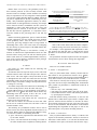
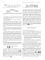
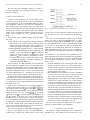
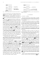
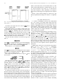
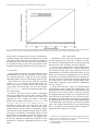
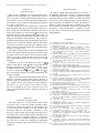
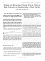
824 IEEE/ACM TRANSACTIONS ON NETWORKING, VOL. 5, NO. 6, DECEMBER 1997 Hashed and Hierarchical Timing Wheels: Efficient Data Structures for Implementing a Timer Facility George Varghese and Anthony Lauck Abstract— The performance of timer algorithms is crucial to many network protocol implementations that use timers for failure recovery and rate control. Conventional algorithms to implement an Operating System timer module take O (n ) time to start or maintain a timer, where n is the number of outstanding timers: this is expensive for large n. This paper shows that by using a circular buffer or timing wheel, it takes O (1) time to start, stop, and maintain timers within the range of the wheel. Two extensions for larger values of the interval are described. In the first, the timer interval is hashed into a slot on the timing wheel. In the second, a hierarchy of timing wheels with different granularities is used to span a greater range of intervals. The performance of these two schemes and various implementation tradeoffs are discussed. We have used one of our schemes to replace the current BSD UNIX callout and timer facilities. Our new implementation can support thousands of outstanding timers without much overhead. Our timer schemes have also been implemented in other operating systems and network protocol packages. Index Terms— Callout facilities, hashed wheels, hierarchical wheels, protocol implementations, Timers, Timer Facilities. I. INTRODUCTION I N a centralized or distributed system, we need timers for the following. Failure Recovery: Several kinds of failures cannot be detected asynchronously. Some can be detected by periodic checking (e.g., memory corruption) and such timers always expire. Other failures can only be inferred by the lack of some positive action (e.g., message acknowledgment) within a specified period. If failures are infrequent, these timers rarely expire. Algorithms in Which the Notion of Time or Relative Time is Integral: Examples include algorithms that control the rate of production of some entity (process control, rate-based flow control in communications), scheduling algorithms, and algorithms to control packet lifetimes in computer networks. These timers almost always expire. Manuscript received November 1, 1996; revised June 19, 1997; approved by IEEE/ACM TRANSACTIONS ON NETWORKING Editor L. Peterson. An earlier version of this paper appeared in Proc. 11th ACM Symp. on Operating Systems Principles, Nov. 1987. The work of G. Varghese was supported by the Office of Naval research under an ONR Young Investigator Award and by the National Science Foundation under Grant NCR 940997. G. Varghese was with Digital Equipment Corporation, Littleton, MA USA. He is now with the Department of Computer Science, Washington University, St. Louis, MO 63130 USA (e-mail: [email protected]). A. Lauck was with Digital Equipment Corporation, Littleton, MA USA. He is now at P.O. Box 59, Warren, VT 05674 USA (e-mail: [email protected]). Publisher Item Identifier S 1063-6692(97)07265-8. The performance of algorithms to implement a timer module becomes an issue when any of the following are true. • The algorithm is implemented by a processor that is interrupted each time a hardware clock ticks, and the interrupt overhead is substantial. • Fine granularity timers are required. • The average number of outstanding timers is large. If the hardware clock interrupts the host every tick, and the interval between ticks is in the order of microseconds, then the interrupt overhead is substantial. Most host operating systems offer timers of coarse (milliseconds or seconds) granularity. Alternately, in some systems finer granularity timers reside in special-purpose hardware. In either case, the performance of the timer algorithms will be an issue as they determine the latency incurred in starting or stopping a timer and the number of timers that can be simultaneously outstanding. As an example, consider communications between members of a distributed system. Since messages can be lost in the underlying network, timers are needed at some level to trigger retransmissions. A host in a distributed system can have several timers outstanding. Consider, for example, a server with 200 connections and 3 timers per connection. Further, as networks scale to gigabit speeds, both the required resolution and the rate at which timers are started and stopped will increase. Several recent network implementations (e.g., [6]) have been tuned to send packets at a rate of 25 000–40 000 packets per second. Some network implementations (e.g., the BSD TCP implementation) do not use a timer per packet; instead, only a few timers are used for the entire networking package. The BSD TCP implementation gets away with two timers because the TCP implementation maintains its own timers for all outstanding packets, and uses a single kernel timer as a clock to run its own timers. TCP maintains its packet timers in the simplest fashion: whenever its single kernel timer expires, it ticks away at all its outstanding packet timers. For example, many TCP implementations use two timers: a 200-ms timer and a 500-ms timer. The naive method works reasonably well if the granularity of timers is low and losses are rare. However, it is desirable to improve the resolution of the retransmission timer to allow speedier recovery. For example, the University of Arizona has a new TCP implementation called TCP Vegas [4] that performs better than the commonly used TCP Reno. One of the reasons TCP Reno has bad performance when experiencing losses is the coarse granularity of the timeouts. 1063–6692/97$10.00 1997 IEEE VARGHESE AND LAUCK: HASHED AND HIERARCHICAL TIMING WHEELS Besides faster error recovery, fine granularity timers also allow network protocols to more accurately measure small intervals of time. For example, accurate estimates of round trip delay are important for the TCP congestion control algorithm [14] and the Scalable Reliable Multicast (SRM) framework [11] that is implemented in the Wb conferencing tool [16]. Finally, many multimedia applications routinely use timers, and the number of such applications is increasing. An example can be found in Siemens’ CHANNELS run time system for multimedia [3] where each audio stream uses a timer with granularity that lies between 10 and 20 ms. For multimedia and other real-time applications, it is important to have worst-case bounds on the processing time to start and stop timers. Besides networking applications, process control and other real-time applications will also benefit from large numbers of fine granularity timers. Also, the number of users on a system may grow large enough to lead to a large number of outstanding timers. This is the reason cited (for redesigning the timer facility) by the developers of the IBM VM/XA SP1 operating system [10]. In the following sections, we will describe a family of schemes for efficient timer implementations based on a data structure called a timing wheel. We will also describe performance results based on a UNIX implementation, and survey some of the systems that have implemented timer packages based on the ideas in this paper. 825 TABLE I AN EXAMPLE OF THE PARAMETERS OF THE TIMER MODULE THAT A NETWORKING APPLICATION WOULD CONSIDER IMPORTANT Routine STARTTIMER STOPTIMER PERTICKBOOKKEEPING EXPIRYPROCESSING Critical Parameter Latency (average and worst-case) Latency (average and worst-case) Latency (average) None TABLE II LATENCY METRICS FOR THREE PREVIOUSLY USED SCHEMES. NOTE THAT STOPTIMER IS (1) FOR UNBALANCED TREES AND [log ( )] FOR BALANCED TREES; BALANCED TREE IMPLEMENTATIONS HAVE THE SLOWEST STOPTIMER BECAUSE OF THE NEED TO REBALANCE THE TREE AFTER A DELETION O Scheme 1 2 3 O STARTTIMER O(1) O(n) O(log (n)) n STOPTIMER O(1) O(1) O(log (n)) or O(1) PERTICK O(n) O(1) O(1) caller of the routine blocks until the routine completes. Both the average and worst case latency are of interest. For example, a client application that implements a transport protocol may find that space is cheap and the critical parameters for each routine in the timer module are as shown in Table I. The performance measures important for the client applications should be used to choose among timer algorithms. III. EXISTING TIMER SCHEMES II. MODEL Our model of a timer module has the following four component routines. STARTTIMER (Interval, RequestId, ExpiryAction): The client calls this routine to start a timer that will expire after “Interval” units of time. The client supplies a RequestId which is used to distinguish this timer from other timers that the client has outstanding. Finally, the client can specify what action must be taken on expiry: for instance, calling a client-specified routine, or setting an event flag. STOPTIMER (RequestId): This routine uses its knowledge of the client and RequestId to locate the timer and stop it. PERTICKBOOKKEEPING: Let the granularity of the timer be units. Then every units this routine checks whether any outstanding timers have expired; if this is the case, it calls STOPTIMER, which in turn calls the next routine. EXPIRYPROCESSING: This routine does the ExpiryAction specified in the STARTTIMER call. The first two routines are activated on client calls while the last two are invoked on timer ticks. The timer is often an external hardware clock. The following two performance measures can be used to choose between the various algorithms described in the rest of this paper. Both of them are parameterized by , the average (or worst-case) number of outstanding timers. 1) Space: The memory required for the data structures used by the timer module. 2) Latency: The time between the invoking of a routine in the timer module and its completion, assuming that the There are two standard schemes. A. Scheme 1—Straightforward Here [22] STARTTIMER finds a memory location and sets that location to the specified timer interval. Every units, PERTICKBOOKKEEPING will decrement each outstanding timer; if any timer becomes zero, EXPIRYPROCESSING is called. This scheme is extremely fast except for per tick bookkeeping. It also uses one record per outstanding timer, the minimum space possible. Its performance is summarized in Table II. It is appropriate if: • there are only a few outstanding timers; • most timers are stopped within a few ticks of the clock; • PERTICKBOOKKEEPING is done with suitable performance by special-purpose hardware. Note that instead of doing a Decrement, we can store the absolute time at which timers expire and do a Compare. This option is valid for all timer schemes we describe; the choice between them will depend on the size of the time-of-day field, the cost of each instruction, and the hardware on the machine implementing these algorithms. In this paper we will use the Decrement option, except when describing Scheme 2. B. Scheme 2—Ordered List Here [22] PERTICKBOOKKEEPING latency is reduced at the expense of STARTTIMER performance. Timers are stored in an ordered list. Unlike Scheme 1, we will store the absolute time at which the timer expires, and not the interval before expiry. 826 IEEE/ACM TRANSACTIONS ON NETWORKING, VOL. 5, NO. 6, DECEMBER 1997 Fig. 1. Timer queue example used to illustrate Scheme 2. Fig. 2. A G/G/Inf/Inf queuing model of a timer module. Note that s(t) is the density function of interval between starting and stopping (or expiration) of a timer. The timer that is due to expire at the earliest time is stored at the head of the list. Subsequent timers are stored in increasing order as shown in Fig. 1. In Fig. 1, the lowest timer is due to expire at absolute time 10 h, 23 min, and 12 s. Because the list is sorted, PERTICKBOOKKEEPING need only increment the current time of day, and compare it with the head of the list. If they are equal, or the time of day is greater, it deletes that list element and calls EXPIRYPROCESSING. It continues to delete elements at the head of the list until the expiry time of the head of the list is strictly less than the time of day. STARTTIMER searches the list to find the position to insert the new timer. In the example, STARTTIMER will insert a new timer due to expire at 10:24:01 between the second and third elements. The worst-case latency to start a timer is O(n). The average latency depends on the distribution of timer intervals (from time started to time stopped), and the distribution of the arrival process according to which calls to STARTTIMER are made. Interestingly, this can be modeled (Fig. 2) as a single queue with infinite servers; this is valid because every timer in the queue is essentially decremented (or served) every timer tick. It is shown in [17], that we can use Little’s result to obtain the average number in the queue; also the distribution of the remaining time of elements in the timer queue seen by a new request is the residual life density of the timer interval distribution. If the arrival distribution is Poisson, the list is searched from the head, and reads and writes both cost one unit, then the average cost of insertion for negative exponential and uniform timer interval distributions is shown in [17] to be — negative exponential — uniform. Results for other timer interval distributions can be computed using a result in [17]. For a negative exponential distribution we can reduce the average cost to by searching the list from the rear. In fact, if timers are always inserted at the rear of the list, this search strategy yields an (1) STARTTIMER latency. This happens, for instance, if all timers intervals have the same value. However, for a general distribution of the timer interval, we assume the average latency of insertion is . Fig. 3. Analogy between a timer module and a sorting module. STOPTIMER need not search the list if the list is doubly linked. When STARTTIMER inserts a timer into the ordered list, it can store a pointer to the element. STOPTIMER can then use this pointer to delete the element in (1) time from the doubly linked list. This can be used by any timer scheme. If Scheme 2 is implemented by a host processor, the interrupt overhead on every tick can be avoided if there is hardware support to maintain a single timer. The hardware timer is set to expire at the time at which the timer at the head of the list is due to expire. The hardware intercepts all clock ticks and interrupts the host only when a timer actually expires. Unfortunately, some processor architectures do not offer this capability. Algorithms similar to Scheme 2 are used by both VMS and UNIX in implementing their timer modules. The performance of the two schemes is summarized in Table II. As for Space, Scheme 1 needs the minimum space possible; Scheme 2 needs extra space for the forward and back pointers between queue elements. IV. SORTING TECHNIQUES AND TIME-FLOW MECHANISMS A. Sorting Algorithms and Priority Queues Scheme 2 reduced PERTICKBOOKKEEPING latency at the expense of STARTTIMER by keeping the timer list sorted. Consider the relationship between timer and sorting algorithms depicted in Fig. 3. However, consider the following. • In a typical sort, all elements are input to the module when the sort begins; the sort ends by outputting all elements in sorted order. A timer module performs a more dynamic sort because elements arrive at different times and are output at different times. • In a timer module, the elements to be “sorted” change their value over time if we store the interval. This is not true if we store the absolute time of expiry. A data structure that allows “dynamic” sorting is a priority queue [7]. A priority queue allows elements to be inserted and deleted; it also allows the smallest element in the set to be found. A timer module can use a priority queue, and do PERTICKBOOKKEEPING only on the smallest timer element. 1) Scheme 3—Tree-Based Algorithms: A linked list (Scheme 2) is one way of implementing a priority queue. For large , tree-based data structures are better. These include unbalanced binary trees, heaps, post-order and end-order trees, and leftist-trees [7], [26]. They attempt to reduce the latency to . in Scheme 2 for STARTTIMER from In [18] it is reported that this difference is significant for large , and that unbalanced binary trees are less expensive than balanced binary trees. Unfortunately, unbalanced binary trees easily degenerate into a linear list; this can happen, for instance, if a set of equal timer intervals are inserted. VARGHESE AND LAUCK: HASHED AND HIERARCHICAL TIMING WHEELS 827 We will lump these algorithms together as Scheme 3: tree-based algorithms. The performance of Scheme 3 is summarized in Table II. B. Discrete Event Simulation In discrete event simulations [19], all state changes in the system take place at discrete points in time. An important part of such simulations are the event-handling routines or timeflow mechanisms. When an event occurs in a simulation, it may schedule future events. These events are inserted into some list of outstanding events. The simulation proceeds by processing the earliest event, which in turn may schedule further events. The simulation continues until the event list is empty or some condition (e.g., clock MaxSimulationTime) holds. There are two ways to find the earliest event and update the clock. 1) The earliest event is immediately retrieved from some data structure (e.g., a priority queue [7]) and the clock jumps to the time of this event. This is embodied in simulation languages like GPSS [12] and SIMULA [9]. 2) In the simulation of digital circuits, it is often sufficient to consider event scheduling at time instants that are multiples of the clock interval, say . Then, after the program processes an event, it increments the clock variable by until it finds any outstanding events at the current time. It then executes the event(s). This is embodied in languages for digital simulation like TEGAS [21] and DECSIM [15]. We have already seen that algorithms used to implement the first method are applicable for timer algorithms: these include linked lists and tree-based structures. What is more interesting is that algorithms for the second method are also applicable. Translated in terms of timers, the second method for PERTICKBOOKKEEPING is: “Increment the clock by the clock tick. If any timer has expired, call EXPIRYPROCESSING.” An efficient and widely used method to implement the second method is the so-called timing-wheel [21], [24] technique. In this method, the data structure into which timers are inserted is an array of lists, with a single overflow list for timers beyond the range of the array. In Fig. 4, time is divided into cycles; each cycle is units of time. Let the current number of cycles be . If the current time pointer points to element , the current time is . The event notice corresponding to an event scheduled to arrive within the current cycle (e.g., at time , for integer between 0 and ) is inserted into the list pointed to by the th element of the array. Any event occurring beyond the current cycle is inserted into the overflow list. Within a cycle, the simulation increments the current time until it finds a nonempty list; it then removes and processes all events in the list. If these schedule future events within the current cycle, such events are inserted into the array of lists; if not, the new events are inserted into the overflow list. The current time pointer is incremented modulo . When it wraps to 0, the number of cycles is incremented, and the overflow list is checked; any elements due to occur in the Fig. 4. Timing wheel mechanism used in logic simulation [21]. current cycle are removed from the overflow list and inserted into the array of lists. This is implemented in TEGAS-2 [21]. The array can be conceptually thought of as a timing wheel; every time we step through locations, we rotate the wheel by incrementing the number of cycles. A problem with this implementation is that as time increases within a cycle and we travel down the array, it becomes more likely that event records will be inserted in the overflow list. Other implementations [15] reduce (but do not completely avoid) this effect by rotating the wheel half-way through the array. In summary, we note that time flow algorithms used for digital simulation can be used to implement timer algorithms; conversely, timer algorithms can be used to implement time flow mechanisms in simulations. However, there are differences to note. • In digital simulations, most events happen within a short interval beyond the current time. Since timing wheel implementations rarely place event notices in the overflow list, they do not optimize this case. This is not true for a general-purpose timer facility. • Most simulations ensure that if two events are scheduled to occur at the same time, they are removed in FIFO order. Timer modules need not meet this restriction. • Stepping through empty buckets on the wheel represents overhead for a digital simulation. In a timer module, we have to increment the clock anyway on every tick. Consequently, stepping through empty buckets on a clock tick does not represent significant extra overhead if it is done by the same entity that maintains the current time. • Simulation languages assume that canceling event notices is very rare. If this is so, it is sufficient to mark the notice as “canceled” and wait until the event is scheduled; at that point, the scheduler discards the event. In a timer module, STOPTIMER may be called frequently; such an approach can cause the memory needs to grow unboundedly beyond the number of timers outstanding at any time. We will use the timing-wheel method below as a point of departure to describe further timer algorithms. V. SCHEME 4—BASIC SCHEME We describe a simple modification of the timing-wheel algorithm. If we can guarantee that all timers are set for 828 Fig. 5. Array of lists used by Scheme 4 for timer intervals up to MaxInterval. periods less than MaxInterval, this modified algorithm takes latency for STARTTIMER, STOPTIMER, and also for PERTICKBOOKKEEPING. Let the granularity of the timer be 1 unit. The current time is represented in Fig. 5 by a pointer to an element in a circular buffer with dimensions [0, MaxInterval 1]. To set a timer at units past current time, we index (Fig. 5) (mod MaxInterval), and put the timer at the into Element head of a list of timers that will expire at a time = Current Time units. Each tick we increment the current timer pointer (mod MaxInterval) and check the array element being pointed to. If the element is 0 (no list of timers waiting to expire), no more work is done on that timer tick. But if it is nonzero, we do expiry processing on all timers that are stored in that . The cost of list. Thus, the latency for STARTTIMER is except when timers expire, but PERTICKBOOKKEEPING is this is the best possible. If the timer lists are doubly linked, and, as before, we store a pointer to each timer record, then . the latency of STOPTIMER is also This is basically a timing-wheel scheme where the wheel turns one array element every timer unit, as opposed to rotating every MaxInterval or MaxInterval/2 units [21]. This guarantees that all timers within MaxInterval of the current time will be inserted in the array of lists; this is not guaranteed by conventional timing wheel algorithms [15], [21]. In sorting terms, this is similar to a bucket sort [7] that trades off memory for processing. However, since the timers change value every time instant, intervals are entered as offsets from the current time pointer. It is sufficient if the current time pointer increases every time instant. elements in time using A bucket sort sorts buckets, since all buckets have to be examined. This is . In timer algorithms, however, inefficient for large the crucial observation is that some entity needs to do work per tick to update the current time; it costs only a few more instructions for the same entity to step through an empty bucket. What matters, unlike the sort, is not the total amount elements, but the average (and worst-case) of work to sort part of the work that needs to be done per timer tick. Still memory is finite: it is difficult to justify 2 words of memory to implement 32 bit timers. One solution is to implement timers within some range using this scheme and the allowed memory. Timers greater than this value are implemented using, say, Scheme 2. Alternately, this scheme can be extended in two ways to allow larger values of the timer interval with modest amounts of memory. IEEE/ACM TRANSACTIONS ON NETWORKING, VOL. 5, NO. 6, DECEMBER 1997 Fig. 6. Array of lists used by Schemes 5 and 6 for arbitrary-sized timers: basically a hash table. VI. EXTENSIONS A. Extension 1—Hashing The previous scheme has an obvious analogy to inserting an element in an array using the element value as an index. If there is insufficient memory, we can hash the element value to yield an index. For example, if the table size is a power of 2, an arbitrary size timer can easily be divided by the table size; the remainder (low order bits) is added to the current time pointer to yield the index within the array. The result of the division (high order bits) is stored in a list pointed to by the index. In Fig. 6, let the table size be 256 and the timer be a 32bit timer. The remainder on division is the last 8 bits. Let the value of the last 8 bits be 20. Then the timer index is 10 (Current Time Pointer) 20 (remainder) 30. The 24 high order bits are then inserted into a list that is pointed to by the 30th element. Other methods of hashing are possible. For example, any function that maps a timer value to an array index could be used. We will defend our choice at the end of this subsection. Next, there are two ways to maintain each list. 1) Scheme 5—Hash Table With Sorted Lists: Here each list is maintained as a ordered list exactly as in Scheme 2. STARTTIMER can be slow because the 24 bit quantity must be inserted into the correct place in the list. Although the worst-case latency for STARTTIMER is still , the average . This is true if TableSize, and latency can be if the hash function (which is TimerValue mod TableSize) distributes timer values uniformly across the table. If so, the average size of the list that the th element is inserted into is TableSize [7]. Since TableSize, the average latency of STARTTIMER is . How well this hash actually distributes depends on the arrival distribution of timers to this module, and the distribution of timer intervals. PERTICKBOOKKEEPING must increment the current time pointer. If the value stored in the array element being pointed to is zero, there is no more work. Otherwise, as in Scheme 2, the top of the list is decremented. If the timer at the top of the list expires, EXPIRYPROCESSING is called and the top list element is deleted. Once again, PERTICKBOOKKEEPING takes average and worst-case latency except when multiple timers are due to expire at the same instant, which is the best we can do. Finally, if each list is doubly linked and STARTTIMER stores a pointer to each timer element, STOPTIMER takes time. VARGHESE AND LAUCK: HASHED AND HIERARCHICAL TIMING WHEELS A pleasing observation is that the scheme reduces to Scheme 2 if the array size is 1. In terms of sorting, Scheme 5 is similar to doing a bucket sort on the low order bits, followed by an insertion sort [7] on the lists pointed to by each bucket. 2) Scheme 6—Hash Table with Unsorted Lists: If a worstcase STARTTIMER latency of is unacceptable, we can maintain each time list as an unordered list instead of an ordered list. Thus, STARTTIMER has a worst case and average . But the per-tick bookkeeping now takes latency of longer. Every timer tick, we increment the pointer (mod TableSize); if there is a list there, we must decrement the high order bits for every element in the array, exactly as in Scheme 1. However, if the hash table has the property described above, then the average size of the list will be . We can make a stronger statement about the average behavior regardless of how the hash distributes. Notice that every TableSize ticks we decrement once all timers that are still living. Thus, for timers, we do TableSize work on average per tick. If TableSize then we do work on average per tick. If all timers hash into the same bucket, then every TableSize ticks we do work, but for intermediate ticks we do work. Thus, the hash distribution in Scheme 6 only controls the variance of the latency of PERTICKBOOKKEEPING, and not the average latency. Since the worst-case latency of PERTICKBOOKKEEPING is always (all timers expire at the same time), we believe that the choice of hash function for Scheme 6 is insignificant. Obtaining the remainder after dividing by a power of 2 is cheap, and consequently recommended. Further, using an arbitrary hash function to map a timer value into an array index would require PERTICKBOOKKEEPING to compute the hash on each timer tick, which would make it more expensive. We discuss implementation strategies for Scheme 6 in Appendix A. B. Extension 2—Exploiting Hierarchy The last extension of the basic scheme exploits the concept of hierarchy. To represent the number 1 000 000 we need only seven digits instead of 1 000 000 because we represent numbers hierarchically in units of 1’s, 10’s, 100’s etc. Similarly, to represent all possible timer values within a 32-bit range, we do not need a 2 element array. Instead we can use a number of arrays, each of different granularity. For instance, we can use four arrays as follows: • a 100-element array in which each element represents a day; • a 24-element array in which each element represents an hour; • a 60-element array in which each element represents a minute; • a 60-element array in which each element represents a second. Thus, instead of million locations to store timers up to 100 days, we need only 100 24 60 60 244 locations. 829 Fig. 7. Hierarchical set of arrays of lists used by Scheme 7 to “map” time more efficiently. As an example, consider Fig. 7. Let the current time be 11 days, 10 h, 24 min, 30 s. Then to set a timer of 50 min and 45 s, we first calculate the absolute time at which the timer will expire. This is 11 days, 11 h, 15 min, 15 s. Then we insert the timer into a list beginning 1 (11–10 hrs) element ahead of the current hour pointer in the hour array. We also store the remainder (15 min and 15 s) in this location. We show this in Fig. 7, ignoring the day array which does not change during the example. The seconds array works as usual: every time the hardware clock ticks, we increment the second pointer. If the list pointed to by the element is nonempty, we process all elements in the list using EXPIRYPROCESSING. However, the other three arrays work slightly differently. Even if there are no timers requested by the user of the service, there will always be a 60-s timer that is used to update the minute array, a 60-min timer to update the hour array, and a 24-h timer to update the day array. For instance, every time the 60-s timer expires, we will increment the current minute timer, do any required expiry processing for the minute timers, and reinsert another 60-s timer. Returning to the example, if the timer is not stopped, eventually the hour timer will reach 11. When the hour timer reaches 11, the list is examined. The expiry processing routine will insert the remainder of the seconds (15) in the minute array, 15 elements after the current minute pointer (0). Of course, if the minutes remaining were zero, we could go directly to the second array. At this point, the table will look like Fig. 8. Eventually, the minute array will reach the 15th element; as part of EXPIRYPROCESSING, we will move the timer into the second array 15 s after the current value. Fifteen seconds later, the timer will actually expire, at which point the user-specified EXPIRYPROCESSING is performed. What are the performance parameters of this scheme? STARTTIMER: Depending on the algorithm, we may need time, where is the number of arrays in the hierarchy, to find the right table to insert the timer and to find the remaining time. A small number of levels should be sufficient to cover the timer range with an allowable amount of memory; thus should be small (say, ). 830 IEEE/ACM TRANSACTIONS ON NETWORKING, VOL. 5, NO. 6, DECEMBER 1997 modes: one for hour timers, one for minute timers, etc. This reduces PERTICKBOOKKEEPING overhead further at the cost of a loss in precision of up to 50% (e.g., a 1-min and 30-s timer that is rounded to 1 min). Alternately, we can improve the precision by allowing just one migration between adjacent lists. Scheme 7 has an obvious analogy to a radix sort [7]. We discuss implementation strategies for Scheme 7 in Appendix A. VII. UNIX IMPLEMENTATION Fig. 8. The previous example, after the hour component of the timer expires (using Scheme 7). STOPTIMER: Once again, this can be done in time if all lists are doubly linked. PERTICKBOOKKEEPING: It is useful to compare this to the corresponding value in Scheme 6. Both have the same average latency of for sufficiently large array sizes but the constants of complexity are different. More precisely: let be the average timer interval (from start to stop or expiry); let be the total amount of array elements available; and let be the total number of levels in the hierarchy. The total work done in Scheme 6 for such an average sized timer is where is a constant denoting the cost of decrementing the high order bits, indexing, etc., in Scheme 6. If a timer lives for units of time, it will be decremented times. And in Scheme 7 it is bounded from above by where represents the cost of finding the next list to migrate to, and the cost of migration, in Scheme 7; is the maximum number of lists to migrate between. The average cost per unit time for an average of timers then becomes — Scheme — Scheme The choice between Scheme 6 and Scheme 7 will depend on the parameters above. Since and will not be drastically different, for small values of and large values of , Scheme 6 can be better than Scheme 7 for both STARTTIMER and PERTICKBOOKKEEPING. However, for large values of and small values of , Scheme 7 will have a better average cost (latency) for PERTICKBOOKKEEPING but a greater cost for STARTTIMER latency. W. Nichols has pointed out that if the timer precision is allowed to decrease with increasing levels in the hierarchy, then we need not migrate timers between levels. For instance, in the example above, we would round off to the nearest hour and only set the timer in hours. When the hour timer goes off, we do the user-specified EXPIRYPROCESSING without migrating to the minute array. Essentially, we now have different timer A. Costello of Washington University has implemented [8] a new version of the BSD UNIX callout and timer facilities. Current BSD kernels take time proportional to the number of outstanding timers to set or cancel timers. The new implementation, which is based on Scheme 6, takes constant time to start, stop, and maintain timers; this leads to a highly scalable design that can support thousands of outstanding timers without much overhead. In the existing BSD implementation, each callout is represented by a callout structure containing a pointer to the function to be called (c func), a pointer to the function’s argument (c arg), and a time (c time) expressed in units of clock ticks. Outstanding callouts are kept in a linked list, sorted by their expiration times. The c time member of each callout structure is differential, not absolute—the first callout in the list stores the number of ticks from now until expiration, and each subsequent callout in the list stores the number of ticks between its own expiration and the expiration of its predecessor. In BSD UNIX, Callouts are set and canceled using routines called timeout() and untimeout(), respectively. The routine timeout(func, arg, time) registers func(arg) to be called at the specified time; untimeout(func, arg) cancels the callout with matching function and argument. Because the calltodo list must be searched linearly, both operations take time proportional to the number of outstanding callouts. Interrupts are locked out for the duration of the search. The Costello implementation is based on Scheme 6 described above. Unfortunately, the existing timeout() interface in BSD does not allow the passing of handles, which was used in all our schemes to quickly cancel a timer. The Costello implementation used two solutions to this problem. For calls using the existing interface, a search for a callout given a function pointer and argument is done using a hash table. A second solution was also implemented: a new interface function was defined for removing a callout (unsetcallout()) that takes a handle as its only argument. This allows existing code to use the old interface and new applications to use the new interface. The performance difference between these two approaches appears to be slight, so the hash table approach appears to be preferable. In the new implementation, the timer routines are guaranteed to lock out interrupts only for a small, bounded amount of time. The new implementation also extends the setitimer() interface to allow a process to have multiple outstanding VARGHESE AND LAUCK: HASHED AND HIERARCHICAL TIMING WHEELS 831 Fig. 9. Real-time performance comparison of BSD UNIX callout implementations. Note that the new callout implementations using timing wheels take constant time. By contrast, the traditional BSD implementation takes time that increases linearly with the number of outstanding callouts. timers, thereby reducing the need for users to maintain their own timer packages. The changes to the BSD kernel are small (548 lines of code added, 80 removed) and are available on the World Wide Web. The details of this new implementation are described elsewhere [8]; the written report contains several important implementation details that are not described here. A. Performance The performance of Scheme 6 was tested (using the Costello implementation). The tests took advantage of the new interface extensions that allow a single process to have multiple outstanding callouts. We quote the following results from [8]. Three kernels were tested on a Sun 4/360. The first kernel used the timeout() interface to the old callout facility. The second kernel used the existing interface but used the new callout facility (and a hash table). The last kernel used the new setcallout() interface (which allows handles) to the new callout facility. In each test, one process created a number of outstanding timers set for random times far in the future, causing a number of outstanding callouts. It then created one more timer, and repeatedly set it for a random time farther in the future than the others, causing repeated calls to untimeout() and timeout() (or unsetcallout() and setcallout(), depending on which kernel was being used). The results (Fig. 9) show that the time for the original callout facility increases linearly with the number of outstanding callouts, whereas the time for the replacement callout facility is constant with respect to the number of outstanding callouts, for both the old interface (using hashing) and the new interface (using handles). The new interface performs very slightly better, and provides guaranteed constant time operations, but the old interface is needed for compatibility with the rest of the kernel. VIII. LATER WORK A preliminary version of the work described in this paper was first described in [25]. Since then, a number of systems have built timer implementations based on this approach, and there have been a few extensions of the basic approach. 1) Systems that Use Timing Wheels: Some well-known network protocol implementations have used the timing wheel ideas described in this paper. These include the fast TCP implementation in [6] and the X-kernel timer facility [1]. The efficient user level protocol implementation in [23] mentions the possible use of timing wheels but did not do an implementation. We also know of commercial networking products that use timing wheels as part of their operating system. These include DEC’s Gigaswitch [20] and Siemens’ CHANNELS run time system [2]. 2) Timing Wheel Extensions: Brown [5] extended the idea of hashed timing wheels to what he calls calendar queues.1 The major difference is that calendar queue implementations also periodically resize the wheel in order to reduce the overhead2 of stepping through empty buckets. For timer applications, the clock time must be incremented on every clock tick anyway; thus adding a few instructions to step through empty buckets is not significant. Davison [10] describes a timer implementation for the IBM VM/XA SP1 operating system based on calendar queues. The empirical improvement in per tick bookkeeping (due to resizing the wheel periodically) does not appear to warrant the extra complexity of resizing. 1 Some authors refer to timing wheels as a variant of calendar queues; given the dates of invention and publication, it is perhaps more accurate to say that calendar queues are an extension of timing wheels. 2 The improvement is not worst-case and is only demonstrated empirically for certain benchmarks. 832 IEEE/ACM TRANSACTIONS ON NETWORKING, VOL. 5, NO. 6, DECEMBER 1997 IX. AN ALGORITHMIC VIEW From an algorithmic point of view, a timing wheel is just a priority queue [7]. It appears to be just an application of bucket sorting techniques to priority queues. However, bucket sorting cannot be used efficiently for all priority queue implementations. Timing wheels work efficiently only for priority queue applications that satisfy the following bounded monotonicity property: any elements inserted into the priority queue are within Max of the last minimum extracted. If this condition is satisfied and the inserted values are all integers, then we can implement the priority queue using a circular array of size Max. New elements are inserted into the circular array based on the difference between their value and the current minimum element. A pointer is kept to the last minimum extracted. To find the new minimum at any point, we simply advance the pointer till an array location is found that contains a valid element. This is exactly what is done in Scheme 4, where Max corresponds to MaxInterval. It is easy to see what goes wrong if the monotonicity condition is not satisfied. If we can insert an element that is smaller than the last minimum extracted, then we cannot advance the pointer to find the new minimum value; the pointer may have to backtrack, leading to a potential search of the entire array. Even with the monotonicity condition, the wheel approach to priority queues still requires stepping through empty buckets. However, the nice thing about timer applications is that many systems must maintain the time of day anyway, and thus the cost of stepping through empty buckets is amortized over the existing cost of incrementing the time-of-day clock. This example illustrates how an algorithm, that may have a poor algorithmic complexity when considered in isolation, can be very efficient when considered as part of a system, where parts of the algorithms cost can be charged to other system components. The bounded monotonicity condition is satisfied by other algorithmic applications. For example, for graphs with integer edge weights, the Dijkstra algorithm for shortest paths and Prim’s algorithm for minimum spanning trees [7] both satisfy the monotonicity condition with Max equal to the maximum edge weight. While it has been observed before [7] that these two algorithms can benefit from bucket sorting using a linear array, the required size of the linear array was supposed to be the equal to the cost of the largest shortest cost path between any two nodes. Our observation shows that a circular array of size equal to the maximum edge weight suffices. While this is a mild observation, it does reduce the memory needs of networking implementations that use Dijkstra’s algorithm and integer edge weights [13]. To the best of our knowledge, the bounded monotonicity condition has not been described before in the literature. The efficiency of the hashed wheel solution (Scheme 6) for larger timer values is based on bounding the number of timers and doing an amortized analysis. This does not appear to have any direct correspondence with bucket sorting. The hierarchical scheme (Scheme 7) uses essentially logarithmic time to insert an element; thus it is comparable in complexity to standard priority queue implementations like heaps [7]. However, the constants appear to be better for Scheme 7. X. SUMMARY AND CONCLUSIONS In this paper, we have examined the relationship between sorting algorithms, time flow mechanisms in discrete event simulations, and timer algorithms. We have extended the timing wheel mechanism used in logic simulation to yield 3 timer algorithms (Schemes 5–7) that have constant complexity for setting, stopping, and maintaining a timer. The extensions include rotating the timing wheel every clock tick, having separate overflow lists per bucket, and using a hierarchical set of timing wheels (Scheme 7): the extensions are necessary because the requirements of a scheduler in a logic simulation and those of a general timer module are different. In choosing between schemes, we believe that Scheme 1 is appropriate in some cases because of its simplicity, limited use of memory, and speed in starting and stopping timers. Scheme 2 is useful in a host that has hardware to maintain the clock and a single timer. Although it takes time to start a timer, the host is not interrupted every clock tick. In a host without hardware support for timers, we believe Schemes 2 and 3 are inappropriate because of the cost of STARTTIMER when there are a large number of outstanding timers. Clearly, this is not uncommon in hosts that have a significant amount of real-time activity or have several open communication links. Scheme 4 is useful when most timers are within a small range of the current time. For example, it could be used by a networking module that is maintaining its own timers. Scheme 5 depends too much on the hash distribution (for a fast STARTTIMER) to be generally useful. However, a variant of this scheme has been implemented in the X-kernel [1]. For a general timer module, similar to the operating system facilities found in UNIX or VMS, that is expected to work well in a variety of environments, we recommend Scheme 6 or 7. The UNIX results described in this paper are encouraging, and show that it is possible to support thousands of outstanding timers at low overhead using Scheme 6. If the amount of memory required for an efficient implementation of Scheme 6 is a problem, Scheme 7 can be pressed into service. Scheme 7, however, will need a few more instructions in STARTTIMER to find the correct table to insert the timer. Both Schemes 6 and 7 can be completely or partially (see Appendix A) implemented in hardware using some auxiliary memory to store the data structures. If a host had such hardware support, the host software would need time to start and stop a timer and would not need to be interrupted every clock tick. Finally, we note that designers and implementers have assumed that protocols that use a large number of timers are expensive and perform poorly. This is an artifact of existing implementations and operating system facilities. Given that a large number of timers can be implemented efficiently, we hope this will no longer be an issue in the design of protocols for distributed systems. VARGHESE AND LAUCK: HASHED AND HIERARCHICAL TIMING WHEELS APPENDIX A HARDWARE ASSIST Since the cost of handling clock interrupts becomes more significant for fine granularity (e.g., microseconds) timers, it may be necessary to employ special-purpose hardware assist. In the extreme, we can use a timer chip which maintains all the data structures (say in Scheme 6) and interrupts host software only when a timer expires. Another possibility is a chip (actually just a counter) that steps through the timer arrays, and interrupts the host only if there is work to be done. When the host inserts a timer into an empty queue pointed to by array element , it tells the chip about this new queue. The chip then marks as “busy.” As before, the chip scans through the timer arrays every clock tick. During its scan, when the chip encounters a “busy” location, it interrupts the host and gives the host the address of the queue that needs to be worked on. Similarly when the host deletes a timer entry from some queue and leaves behind an empty queue it needs to inform the chip that the corresponding array location is no longer “busy.” Note that the synchronization overhead is minimal because the host can keep the actual timer queues in its memory which the chip need not access, and the chip can keep the timing arrays in its memory, which the host need not access. The only communication between the host and chip is through interrupts. In Scheme 6, the host is interrupted an average of times per timer interval, where is the average timer interval and is the number of array elements. In Scheme 7, the host is interrupted at most times, where is the number of levels in the hierarchy. If and are small and is large, the interrupt overhead for such an implementation can be made negligible. Finally, we note that conventional hardware timer chips use Scheme 1 to maintain a small number of timers. However, if Schemes 6 and 7 are implemented as a single chip that operates on a separate memory (that contains the data structures), then there is no a priori limit on the number of timers that can be handled by the chip. Clearly the array sizes need to be parameters that must be supplied to the chip on initialization. APPENDIX B SYMMETRIC MULTIPROCESSING If the host consists of a set of processors, each of which can process calls to the timer module (symmetric multiprocessing), S. Glaser has pointed out that algorithms that tie up a common data structure for a large period of time will reduce efficiency. For instance, in Scheme 2, when Processor A inserts a timer into the ordered list, other processors cannot process timer module routines until Processor A finishes and releases its semaphore. Schemes 5–7 seem suited for implementation in symmetric multiprocessors. However, given the recent research into techniques for maintaining consistency in multiprocessors, these differences may not be significant. 833 ACKNOWLEDGMENT B. Spinney suggested extending Scheme 4 to Scheme 5. H. Wilkinson independently thought of exploiting hierarchy in maintaining timer lists. J. Forecast helped the authors implement an early version of Scheme 6. A. Black commented on an earlier version and helped improve the presentation. A. Black, B. Spinney, H. Wilkinson, S. Glaser, W. Nichols, P. Koning, A. Kirby, M. Kempf, and C. Kaufman (all at DEC) were a pleasure to discuss these schemes with. The authors are grateful to E. Cooper, M. Bjöorkman, C. Thekath, V. Seidel, B. Souza, and A. Costello for giving information about their implementations. REFERENCES [1] M. Björkman, personal communication. [2] S. Boecking and V. Seidel, “TIP’s protocol run-time system,” in EFOCN’94, June 1994. [3] S. Boecking, V. Seidel, and P. Vindeby, “CHANNELS—A run-time system for multimedia protocols,” in ICCCN’95, Sept. 1995. [4] L. Brakmo, S. O Malley, and L. Peterson, “TCP Vegas: New techniques for congestion detection and avoidance,” in Proc. ACM SIGCOMM’94, London, England. [5] R. Brown, “Calendar queues: A fast (1) priority queue implementation for the simulation event set problem,” Commun. ACM, vol. 31, no. 10, pp. 1220–1227, Oct. 1988. [6] D. D. Clark, V. Jacobson, J. Romkey, and H. Salwen, “An analysis of TCP processing overhead,” IEEE Commun. Mag., vol. 27, no. 6, pp. 23–29, June 1989. [7] T. Cormen, C. Leiserson, and R. Rivest, Introduction to Algorithms. Cambridge, MA: MIT Press/McGraw-Hill, 1990. [8] A. Costello and G. Varghese, “Redesigning the BSD callout and timeout facilities,” Dept. Computer Science, Washington Univ., St. Louis, MO, Tech. Rep. 95-23, Sept. 1995. [9] O.-J. Dahl, B. Myhrhaug, and K. Nygaard, SIMULA’67 Common Base Language, Norwegian Computing Center, Forksningveien, 1B, Oslo 3, Pub. S22. [10] G. Davison, “Calendar p’s and q’s,” Commun. ACM, vol. 32, no. 10, pp. 1241–1242, Oct. 1989. [11] S. Floyd, V. Jacobson, S. McCanne, C. Liu, and L. Zhang, “A reliable multicast framework for light-weight sessions and application level framing,” in Proc ACM SIGCOMM’95, Boston, MA. [12] General Purpose Simulation System 360—User’s Manual, IBM Corp., White Plains, NY, Pub. H20-0326, 1968. [13] International Organization for Standardization (ISO), “Protocol for providing the connectionless-model network service,” Draft International Standard 8473, Mar. 1988. [14] V. Jacobson, “ Congestion avoidance and control,” in Proc. ACM SIGCOMM’88, Stanford, CA. [15] M. A. Kearney, “DECSIM: A multi-level simulation system for digital design,” in 1984 Int. Conf. Computer Design. [16] S. Mccanne, “A distributed whiteboard for network conferencing,” University of California–Berkeley, Computer Networks Term project CS 268, May 1992. [17] C. M. Reeves, “Complexity analysis of event set algorithms,” Computer J., vol. 27, no. 1, 1984. [18] B. Myhrhaug, Sequencing Set Efficiency, Norwegian Computing Center, Forksningveien, 1B, Oslo 3, Pub. A9. [19] A. A. Pritsker and P. J. Kiviat, Simulation with GASP-II. Englewood Cliffs, NJ: Prentice-Hall, 1969. [20] R. Souza et al., “GIGAswitch system: A high-performance packetswitching platform,” Digital Tech. J., vol. 6, no. 1, Winter 1994. [21] S. Szygenda, C. W. Hemming, and J. M. Hemphill, “Time flow mechanisms for use in digital logic simulations,” in Proc. 1971 Winter Simulation Conf., New York. [22] A. S. Tanenbaum, Computer Networks, 3rd ed. Upper Saddle River, NJ: Prentice-Hall, 1996. [23] C. Thekkath, T. Nguyen, E. Moy, and E. Lazowska, “Implementing network protocols at user level,” IEEE Trans. Networking, vol. 1, pp. 554–564, Oct. 1993. [24] E. Ulrich, “Time-sequenced logical simulation based on circuit delay and selective tracing of active network paths,” in 1965 ACM Nat. Conf. O 834 [25] G. Varghese and A. Lauck, “Hashed and hierarchical timing wheels: Data structures for the efficient implementation of a timer facility,” in Proc. 11th ACM Symp. Operating Syst. Principles, Nov. 1987, pp. 171–180. [26] J. G. Vaucher and P. Duval, “A comparison of simulation event list algorithms,” Commun. ACM, vol. 18, 1975. George Varghese received the Ph.D. degree in computer science from the Massachusetts Institute of Technology (MIT), Cambridge, in 1992. He worked from 1983 to 1993 at Digital designing network protocols and doing systems research as part of the DECNET architecture and advanced development group. He has worked on designing protocols and algorithms for DECNET and GIGAswitch products. He is currently an Associate Professor of Computer Science at Washington University, St. Louis, MO, where he works on distributed algorithms and efficient algorithms for network implementations. Dr. Varghese has been awarded six patents with colleagues at DEC, with six more patents being applied for. His Ph.D. dissertation on self-stablization was jointly awarded the Sprowls Prize for best thesis in Computer Science at MIT. He was among two computer scientists to receive the ONR Young Investigator Award in 1996. IEEE/ACM TRANSACTIONS ON NETWORKING, VOL. 5, NO. 6, DECEMBER 1997 Tony Lauck received the B.A. degree from Harvard University, Cambridge, MA. He is currently an independent computer networking consultant. A former Corporate Consulting Engineer at Digital Equipment Corporation, he was responsible for Digital’s network architecture for 18 years. Mr. Lauck was a member of the Internet Architecture Board (IAB) from 1990 to 1994.