1
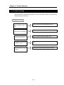
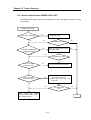
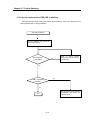
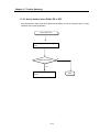
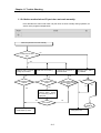
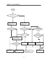
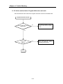
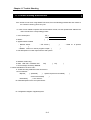
Chapter 11 Trouble Shooting
Chapter 11 Trouble Shooting
Here describes the contents of each error to be occurred while operating the system, the
method to find the cause and the action.
11.1 Basic Procedure of Trouble Shooting
It is important to use the high reliable machine to increase the system reliability but it is
important to take a prompt action when the trouble occurs as well.
To start the system promptly, it is more important to find the trouble occurring cause
promptly and take the necessary action. The basic items to comply when taking this trouble
shooting are as follows.
1) Check by the naked eye
Check the following items by the naked eye.
• Machine action status (stop, action)
• Power appliance status
• I/O machine status
• Wiring status (I/O cable, extended or communication cable)
• Check the indication status of each indicator (POWER LED, RUN LED, ERR LED, TX
LED,RX LED, MS LED,NS LED, I/O LED etc.) and connect the peripheral device and then
check the PLC action status or the program contents.
2) Check the trouble
Examine how the trouble is changed by the following action.
• Place the key switch on STOP position and apply the power ON/OFF.
3) Limit range
Estimate what is the trouble cause using the above method.
• Is it the cause from PLC itself? Or external cause?
• Is it the cause from I/O part? Or other cause?
• Is it the cause from PLC program?
11-1
Chapter 11 Trouble Shooting
11.2 Trouble Shooting
Here describes the trouble finding method, the error code and the actions on the above by
dividing them per phenomenon.
Description of Trouble
When POWER LED is
OFF
When ERR LED is blinking
Action method when POWER LED is OFF.
Action method when ERR LED is blinking.
Action method when RUN LED is OFF.
When RUN LED is OFF.
In case of abnormal
operation I/O part
When program write does
not work
Action method in case of abnormal operation of I/O
part
Action method when program write does not work.
11-2
Chapter 11 Trouble Shooting
11.2.1 Action method when POWER LED is OFF.
Here describes the action order when POWER LED is OFF while apply the power or during
the operation.
POWER LED is OFF
Is the power supplying?
Yes
No
Supply the power.
No
Is POWER LED ‘ON’?
Meet the supply power within
the regular range.
No
Is the power voltage within
the allowable range?
Yes
Yes
Yes
No
Is POWER LED ‘ON’?
Is the power cable
connected well?
No
Connect power cable completely.
Yes
Is the over current
protection acting?
No
1) Check the current capacity and
reduce the over current..
2) After input power OFF, then
power ON.
No
Yes
After writing the trouble
shooting questionnaire, contact
the customer center
Is POWER LED
‘ON’?
Yes
End
11-3
Chapter 11 Trouble Shooting
11.2.2 Action method when ERR LED is blinking.
Here describes the action order when ERR LED is blinking in case of the power input, or
when operation start, or during operation.
ERR LED is blinking.
Connect GMWIN and check the
error code contents.
Is it warning error
(_CNF_WAR) ?
Yes
Refer to typical system
warning flag and remove the
trouble cause.
No
Yes
Is ERR LED keeping
on blinking ?
No
After writing the trouble shooting
questionnaire and contact the
customer center.
End
11-4
Chapter 11 Trouble Shooting
11.2.3 Action method when RUN LED is OFF
Here describes the action order when RUN LED is blinking in case of the power input, or when
operation start, or during operation.
RUN LED is OFF
After the power unit OFF, apply it
ON.
Is RUN LED ‘OFF’?
No
Yes
Contact
center.
to
the
customer
11-5
End
Chapter 11 Trouble Shooting
11.2.4 Action method when I/O part does not work normally.
Here describes the action order when I/O part does not work normally during operation, as
shown on the program example below.
When I/O part does not work normally,
No
Is output LED of SOL1
‘ON’?
Yes
Measure SOL1 terminal
voltage by the tester.
Make the correct wiring.
No
Change the connector of
terminal stand.
No
No
Is the measured value
normal?
Monitor SOL1 status
by GMWIN.
Is the output wiring
correct?
Is the contact status of
terminal stand connector
good?
Yes
Yes
Yes
Yes
Is it normal?
No
After
removing
the
external wiring, check
the monitoring status of
output part.
No
Yes
Is it normal?
Cont’d
Check the output
Change the unit.
machine(SOL1) status.
11-6
Chapter 11 Trouble Shooting
Continuance
No
Is SWITCH1, 2 LED
‘ON’?
Yes
Measure the terminal
voltage of SWITCH1, 2
by the tester.
Measure the terminal
voltage of SWITCH1, 2
by the tester.
Is the measured value
normal?
Is the measured value
normal?
Is the tightening
status of terminal
good?
Yes
No
No
No
Yes
Yes
Is the contact
status of terminal stand
connector good?
Is input wiring correct?
After removing the external
wiring, check the input
status by the forced input.
Is the measured value
normal?
Yes
No
No
Make the correct
wiring.
Tighten the terminal
screw completely.
Change the terminal
stand connector.
No
Yes
Change the unit.
Check all from
beginning again.
Check the input machine
(SWITCH1, 2).
11-7
the
Change the unit.
Chapter 11 Trouble Shooting
11.2.5 Action method when Program Write does not work
Here describes the action order when Program write does not work in the Master CPU.
Program write does not work
Is the key switch set as remote
STOP mode?
No
Put the key switch to remote
STOP mode and run Program
write.
Yes
Is ERR. LED
blinking?
Yes
End
11-8
After reading the error code by
using the peripherals, correct it
according to the contents.
Chapter 11 Trouble Shooting
11.3 Trouble Shooting Questionnaire
If the trouble occurs when using SMART I/O series, fill in the following questionnaire and contact to
the customer center by phone or by fax.
In case of error related to specific and communication module, use the questionnaire added to the
user’s manual of the corresponding product.
1. User contact point :
TEL.)
FAX)
2. Model :
(
)
3. Applied machine details
− Network status :
(
− OS version (
− Serial no. of product
),
)
− GMWIN version no. used in program compile : (
)
4. brief description of control object machine and system :
5. Network model using :
6. ERR LED ‘OFF’ of network unit?
Yes(
), No(
)
7. Error message content by GMWIN :
8. Action trial status for the error code. :
9. Trouble shooting method for other error action :
10. Error features
Repeat(
) : periodical(
) , specific sequence level related(
environment related(
Intermittent(
)
) : error interval :
12. Detail description for the error phenomena :
13. Configuration diagram of applied system:
11-9
)