1
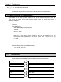
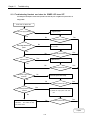
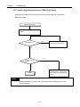
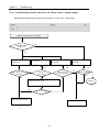
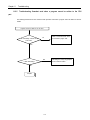
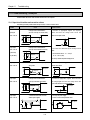
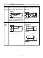
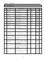
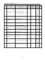
Chapter 11.
Troubleshooting
Chapter 11 TROUBLESHOOTING
The following explains contents, diagnosis and corrective actions for various errors that can occur during system operation.
11.1 Basic Procedures of Troubleshooting
System reliability not only depends on reliable equipment but also on short downtimes in the event of faults. The
short discovery and corrective action is needed for speedy operation of system. The following shows the basic i
nstructions for troubleshooting.
1) Visual checks
Check the following points.
• Machine operating condition (in stop and operating status)
• Power On/Off
• Status of I/O devices
• Condition of wiring (I/O wires, extension and communications cables)
• Display states of various indicators (such as POWER LED, RUN LED, ERR. LED and I/O LED). Afte
r checking them, connect peripheral devices and check the operation status of the PLC and the prog
ram contents.
2) Trouble Check
Observe any change in the error conditions during the following.
• Switch to the STOP position, and then turn the power on and off.
3) Narrow down the possible causes of the trouble where the fault lies, i.e.:
• Inside or outside of the PLC?
• I/O module or another module?
• PLC program?
11.2
Troubleshooting
This section explains the procedure for determining the cause of troubles as well as the errors and correctiveactions.
Is the power LED turned OFF?
Flowchart used when the POWER LED is turned OFF
Is the ERR LED flickering?
Flowchart used when the ERR LED is flickering
Are the RUN LED turned OFF?
Flowchart used when the RUN turned OFF.
I/O module doesn’t operate pro
perly
Flowchart used when the output load of the output module
doesn’t turn on.
Program cannot be written
Flowchart used when a program can’t be written to the PLC
11-1
Chapter 11.
Troubleshooting
11.2.1 Troubleshooting flowchart used when the POWER LED turns OFF.
The following flowchart explains corrective action procedure used when the power is supplied or the power led turns off
during operation.
Power LED is turned OFF
Supply the power.
Is the power supply operating?
No
Yes
No
No
Is the voltage within the rated
Is the fuse blown?
No
Yes
Does the power led turn on?
No
No
Yes
Does the power led turn on?
Connect the power cable correctly.
Yes
No
Over current protection device
activated?
Yes
Replace the fuse.
No
Is the power supply cable
connected?
Yes
See the power supply be within
AC 110-240 V.
power?
Yes
Does the power led turn on?
Yes
Does the power led turn on?
Yes
1) Eliminate the excess current
2) Switch the input power OFF then
ON
No
Write down the troubleshooting qu
estionnaire
and contact the near
est service center
No
Does the power led turn on?
Yes
Complete
11-2
Chapter 11.
Troubleshooting
11.2.2 Troubleshooting flowchart used when the ERR LED is flickering
The following flowchart explains corrective action procedure use when the power is supplied starts or the ERR LED is
flickering during operation.
ERR LED goes flickering.
Check the error code, with connected
GMWIN.
Yes
CNF WAR error?
See App-2 “System Warning Flag”
and remove the cause of the error.
No
Yes
Is ERR Led still
flickering?
No
Write down the
Troubleshooting questionnaires
and contact the nearest service
center.
Complete
REMARK
Though CNF WAR appears, PLC system doesn’t stop but corrective action is needed promptly. If not, it may
cause the system failure.
11-3
Chapter 11. Troubleshooting
11.2.3 Troubleshooting flowchart used when the RUN turns off.
The following flowchart explains corrective action procedure to treat the lights-out of RUN LED when the power is supplied,
operation starts or operation is in the process.
RUN LED is off.
Turn the power unit off and on.
No
Is RUN LED off?
Yes
Contact the nearest service
center.
11-4
Complete
Chapter 11.
Troubleshooting
11.2.4 Troubleshooting flowchart used when the I/O part doesn’t operate normally.
The following flowchart explains corrective action procedure used when the I/O module doesn’t operate normally.
When the I/O module doesn’t work normally.
Is the indicator LED of
the SOL1 on?
NO
Yes
Measure the voltage of power
supply in SOL1
Replace the connector of the
terminal board
Correct wiring.
Check the status of SOLI
by GMWIN
.
NO
NO
Is the
NO
voltage of power supply for load
applied?
NO
Is the
terminal connector
connector appropriate?
Is the output
wiring correct?
YES
Is it normal condition?
YES
YES
YES
Separate the external wiring than check the
condition of output module.
YES
Is it normal condition?
Continue
No
Check the status of SOLI
Replace the Unit
11-5
Chapter 11.
Troubleshooting
Continue
Are the indicator LED of the
switch 1 and 2 on?
No
YES
Check the status of the
switch 1and 2
Check the status of the
switch 1and 2
.
Is input wiring correct?
Is input wiring correct?
Is the
terminal screw tighten
securely?
YES
NO
NO
YES
NO
YES
Separate the external witch then check
the status of input by for a
YES
Is the condition
of the terminal board connector
appropriate?
Is input wiring correct?
NO
Correct wiring
Correct the wiring
NO
Retighten
the
terminal screw
Replace the terminal
board connector
NO
YES
Unit replacement is
needed
Check the status of the
switch 1and 2
Check from the beginning
11-6
Unit replacement is
needed
Chapter 11.
Troubleshooting
11.2.5
Troubleshooting flowchart used when a program cannot be written to the CPU
part
The following flowchart shows the corrective action procedure used when a program cannot be written to the PLC
module.
Program cannot be written to the PC CPU
Is the mode-setting switch set the re
mote STOP?
No
Switch to the remote STOP mode
and ex ecute the program write.
YES
YES
Is ERR. LED blinking?
NO
Complete
11-7
After reading error code by using peripheral
device, correct the contents.
Chapter 11.
Troubleshooting
11.3 Troubleshooting Questionnaire
When problems have been met during operation of the GM7 series, please write down this
Questionnaires and contact the service center via telephone or facsimile.
Ÿ For errors relating to special or communication modules, use the questionnaire included in the
User’s manual of the unit.
Telephone & FAX No
Tell)
FAX)
Using equipment model:
Details of using equipment
CPU model:
OS version No.(
),
Serial No.(
)
GMWIN version No. used to compile programs: (
)
General description of the device or system used as the control object:
5. The kind of the base unit:
− Operation by the mode setting switch (
),
− Operation by the GMWIN or communications (
− External memory module operation
),
(
),
6. Is the ERR. LED of the CPU module turned ON? Yes(
), No(
)
7. GMWIN error message:
8. Used initialization program: initialization program (
)
9. History of corrective actions for the error message in the article 7:
10. Other tried corrective actions:
11. Characteristics of the error
Ÿ Repetitive(
Ÿ Sometimes(
): Periodic(
), Related to a particular sequence(
): General error interval:
12. Detailed Description of error contents:
13. Configuration diagram for the applied system:
11-8
), Related to environment(
)
Chapter 11.
Troubleshooting
11.4 Troubleshooting Examples
Possible troubles with various circuits and their corrective actions are explained.
11.4.1 Input circuit troubles and corrective actions
The followings describe possible troubles with input circuits, as well as corrective actions.
Cause
Condition
Input signal
Corrective Actions
Leakage current of external device
Ÿ Connect an appropriate register and capacity,
(Such as a drive by non-contact switch)
which will make the voltage lower across the
doesn’t turn off.
AC input
C
R
terminals of the input module.
Leakage current
AC input
C
~
External device
R
~
Input signal
doesn’t turn off.
Leakage current of external device
Ÿ CR values are determined by the leakage current
(Drive by a limit switch with neon lamp)
value.
(Neon lamp
AC input
C
may be still on)
− Recommended value C : 0.1 ~ 0.47 ㎌
Leakage current
R: 47 ~ 120 Ω (1/2W)
R
Input signal
doesn’t turn off.
Or make up another independent display circuit.
~
External device
Leakage current due to line capacity of
Ÿ Locate the power supply on the external device
wiring cable.
side as shown below.
AC input
AC input
Leakage current
~
External device
Input signal
doesn’t turn off.
~
External device
Leakage current of external device
Ÿ Connect an appropriate register, which will make
(Drive by switch with LED indicator)
the voltage higher than the OFF voltage across the
DC input
input module terminal and common terminal.
DC input
Leakage current
R
R
External device
Input signal
doesn’t turn off.
Ÿ Sneak current due to the use of two
Ÿ Use only one power supply.
different power supplies.
Ÿ Connect a sneak current prevention diode.
DC input
E1
E2
DC input
E1
L
E
2
11-9
L
Chapter 11.
Troubleshooting
Ÿ E1 > E2, sneaked.
11-10
Chapter 11.
Troubleshooting
11.4.2 Output circuit troubles and corrective actions
The following describes possible troubles with input circuits, as well as their corrective actions.
Condition
Cause
Corrective Action
When the output is
ŸLoad is half-wave rectified inside (in some cases, it is true
Ÿ Connect registers of tens to hundreds KΩ across the
off,
of a solenoid)
load in parallel.
excessive
voltage is applied to
ŸWhen the polarity of the power supply is as shown in ①,
the load.
C is charged. When the polarity is as shown in ②, the
R
voltage charged in C plus the line voltage are applied
across D. Max. voltage is approx. 2√2.
D
¬
D
C
~
R
C
~
R
Load
Load
*) If a resistor is used in this way, it does not pose a
problem to the output element. But it may make the
performance of the diode (D), which is built in the load,
drop to cause problems.
The load doesn’t
Ÿ Leakage current by surge absorbing circuit, which is
Ÿ Connect C and R across the load, which are of registers
turn off.
connected to output element in parallel.
of tens KΩ. When the wiring distance from the output
module to the load is long, there may be a leakage current
Output
due to the line capacity.
Load
C
C
R
~
Leakage current
R
R
Load
Load
When the load is C-
Ÿ Leakage current by surge absorbing circuit, which is
Ÿ Drive the relay using a contact and drive the C-R type
R type timer, time
connected to output element in parallel.
timer using the since contact.
constant fluctuates.
Ÿ Use other timer than the C−R contact some timers have
Output
C
R
half-ware rectified internal circuits therefore, be cautious.
Load
~
Leakage current
T
Timer
X
Output
The load does not
Ÿ Sneak current due to the use of two different power
Ÿ Use only one power supply.
turn off.
supplies.
Ÿ Connect a sneak current prevention diode.
~
Output
Output
Load
Load
E1
E
2
E1<E2, sneaks. E1 is off (E2 is on), sneaks.
E
2
E
1
If the load is the relay, etc, connect a counter-electromotive
voltage absorbing code as shown by the dot line.
11-11
Chapter 11.
Troubleshooting
Output circuit troubles and corrective actions (continued).
Condition
Cause
Corrective actions
The load off
Ÿ Over current at off state [The large solenoid current
Ÿ Insert a small L/R magnetic contact and drive the load
response time
fluidic load (L/R is large) such as is directly driven with
using the same contact.
is long.
the transistor output.
Output
Output
Off current
Load
E
1
Load
Ÿ The off response time can be delay ed by one or
more second as some loads make the current flow
across the diode at the off time of the transistor
output.
Output
transistor
destroyed.
Surge current of the white lamp
Ÿ To suppress the surge current make the dark current
is
of 1/3 to 1/5 rated current flow.
Output
Output
R
E1
E
1
Sink type transistor output
A surge current of 10 times or more when turned on.
Output
R
E
1
Source type transistor output
11-12
Chapter 11.
Troubleshooting
11.5 Error code list
Error
Cause
Contact the A/S center if it reactively occurs when
2
OS ROM error
3
OS RAM error
4
IC (RTC) error
5
Fault processor
6
Program memory fault
7
Data memory fault
10
20
22
Corrective action
the power is re-applied.
Contact the A/S center if it reactively occurs when
the power is re-applied.
Contact the A/S center if it reactively occurs when
the power is re-applied.
Contact the A/S center if it reactively occurs when
the power is re-applied.
Contact the A/S center if it reactively occurs when
the power is re-applied.
Contact the A/S center if it reactively occurs when
the power is re-applied.
Watch dog error due to RE-ap
ply the power
Re-apply the power
Operation
ERR. LED
Diagnosis
Restart
status
Flickering cycle
time
mode
Defect
0.4 sec.
Defect
0.4 sec.
Defect
0.4 sec.
Defect
0.4 sec.
Defect
0.4 sec.
Defect
0.4 sec.
Reset
−
STOP
0.4 sec.
Replace the battery if it has error check the p
Program
rogram after cc-loading it, and if an error is detected
Memory backup error
replace the CPU module.
Memory module program fault
Correct the memory module program and reoperate the system.
When power
is applied.
When power
is applied.
When power
is applied.
When power
is applied.
When power
is applied.
When power
is applied.
During run
When power
is applied.
−
−
−
−
−
−
Cold
Cold
Change into
STOP
0.4 sec.
the
RUN
Cold
mode
Change into
23
An normal program
Re-load the program and start it
STOP
0.4 sec.
the
RUN
Cold
mode
Inconsistency
30
between
the
specified modules by parameters
and the loaded modules
Module type inconsistency error
Refer to the flags (_IO_TYER, IO_TYER_N,
IO_TYER [n]) and correct the in corrective slot, and
Change into
STOP
0.4 sec.
the
RUN
Cold
mode
restart the system.
Module mounting/ dismounting error
31
Module dismounting or additional
Refer to the flags (_IO_DEER, _IO_DEER_N,
mounting during run
_IO_DEER [n]) and correct the in corrective slot,
STOP
0.4 sec.
STOP
0.4 sec.
When scan
completes
Cold
and restart the system.
Fuse disconnection error
32
Fuse disconnection during run
Refer to the flags (_FUSE_ER, FUSE_ER_N,
FUSE_ER [n]) and correct the in corrective slot, and
When scan
completes
Cold
restart the system.
When scan
33
Abnormal I/D module data access
during run
I/O module read/write error
Refer to the flags (_SP_IFER, _IP_IFER_N,
_IP_IFER [n]) and restart the system.
completes
STOP
0.4 sec.
During
execution of
program
11-13
Cold
Chapter 11.
Troubleshooting
Error
Cause
Corrective action
ERR. LED
Operation
Flickering
status
cycle
Diagnosis
Restart
time
mode
When power
is applied.
34
Abnormal special link module data
access during run
Special/link module interface error
Refer to the flags (_SP_IFER, _IP_IFER_N,
When scan
STOP
0.4 sec.
_IP_IFER [n]) and restart the system.
completes
Cold
During
execution of
program
40
41
During run, Scan time over than
Check the scan delay time specified by parameters
the scan delay time specified by
and correct the parameters or the program, and
parameters
then restart the program.
Unreadable instructions in the user
program.
During
STOP
0.4 sec.
During
Re-load the program and restart it.
STOP
0.4 sec.
100
External device fatal error.
101
The ‘E_STOP’ function has been
executed.
Communications
execution of
Cold
program
(ANNUN_ER, _ANC_ERR [n]) and correct the fault
STOP
0.4 sec.
devices and then restart the system.
60
Cold
program
Refer to the external device fatal error. Flag
50
execution of
Correct the program so that the error elements that
invoked the ‘E_STOP’ function can be eliminated in
STOP
−
configuration error
STOP
0.4 sec.
STOP
0.4 sec.
number with in 8.
Special/ Communications module
Adjust the number of high-speed communications
initialization failure
modules loaded.
Cold
execution of
−
program
If the number of computer 4 communications
module is included, then adjust the maximum
completes
During
the program and restart the system (cold restart).
module
When scan
When power
is applied.
When power
is applied.
Cold
Cold
When power
500
Data memory backup error
If the batter has no error.
RUN
−
is applied.
When scan
Cold
completes
When power
501
RTC data error
If the battery has no error, reset the time using the
SMWIN.
RUN
2 sec.
is applied.
When scan
−
completes
When power
502
Lower battery voltage
Replace the battery, which the power is being
applied.
RUN
4 sec.
is applied.
When scan
completes
11-14
−


![[13] Chap.11 Trouble Shooting](http://vs1.manualzilla.com/store/data/005753222_1-b84b48489eb920e39ff2c53b244a8bf5-150x150.png)