1
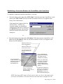
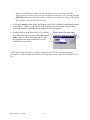
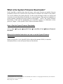
User Manual Document: D5128 Part: D301428X012 May, 2010 BSI_Config User’s Guide Remote Automation Solutions www.EmersonProcess.com/Remote OpenBSI Version 5.8 IMPORTANT! READ INSTRUCTIONS BEFORE STARTING! Be sure that these instructions are carefully read and understood before any operation is attempted. Improper use of this device in some applications may result in damage or injury. The user is urged to keep this book filed in a convenient location for future reference. These instructions may not cover all details or variations in equipment or cover every possible situation to be met in connection with installation, operation or maintenance. Should problems arise that are not covered sufficiently in the text, the purchaser is advised to contact Emerson Process Management, Remote Automation Solutions division (RAS) for further information. EQUIPMENT APPLICATION WARNING The customer should note that a failure of this instrument or system, for whatever reason, may leave an operating process without protection. Depending upon the application, this could result in possible damage to property or injury to persons. It is suggested that the purchaser review the need for additional backup equipment or provide alternate means of protection such as alarm devices, output limiting, fail-safe valves, relief valves, emergency shutoffs, emergency switches, etc. If additional information is required, the purchaser is advised to contact RAS. RETURNED EQUIPMENT WARNING When returning any equipment to RAS for repairs or evaluation, please note the following: The party sending such materials is responsible to ensure that the materials returned to RAS are clean to safe levels, as such levels are defined and/or determined by applicable federal, state and/or local law regulations or codes. Such party agrees to indemnify RAS and save RAS harmless from any liability or damage which RAS may incur or suffer due to such party's failure to so act. ELECTRICAL GROUNDING Metal enclosures and exposed metal parts of electrical instruments must be grounded in accordance with OSHA rules and regulations pertaining to "Design Safety Standards for Electrical Systems," 29 CFR, Part 1910, Subpart S, dated: April 16, 1981 (OSHA rulings are in agreement with the National Electrical Code). The grounding requirement is also applicable to mechanical or pneumatic instruments that include electrically operated devices such as lights, switches, relays, alarms, or chart drives. EQUIPMENT DAMAGE FROM ELECTROSTATIC DISCHARGE VOLTAGE This product contains sensitive electronic components that can be damaged by exposure to an electrostatic discharge (ESD) voltage. Depending on the magnitude and duration of the ESD, this can result in erratic operation or complete failure of the equipment. Read supplemental document S14006 for proper care and handling of ESD-sensitive components. Remote Automation Solutions A Division of Emerson Process Management 1100 Buckingham Street, Watertown, CT 06795 Telephone (860) 945-2200 Emerson Process Management Training GET THE MOST FROM YOUR EMERSON INSTRUMENT OR SYSTEM Avoid Delays and problems in getting your system on-line Minimize installation, start-up and maintenance costs. Make the most effective use of our hardware and software. Know your system. As you know, a well-trained staff is essential to your operation. Emerson offers a full schedule of classes conducted by full-time, professional instructors. Classes are offered throughout the year at various locations. By participating in our training, your personnel can learn how to install, calibrate, configure, program and maintain your Emerson products and realize the full potential of your system. For information or to enroll in any class, go to http://www.EmersonProcess.com/Remote and click on “Educational Services” or contact our training department in Watertown at (860) 945-2200. BLANK PAGE Table of Contents What is BSI_Config? .................................................................................................................... 1 How do I Install BSI_Config?...................................................................................................... 1 What is included in BSI_Config? ................................................................................................ 2 What is TechView Used For?....................................................................................................... 2 How to Start TechView.............................................................................................................. 3 Where to find detailed instructions on how to use TechView ................................................... 3 What is the Diagnostics Program Used For? ............................................................................. 4 How to start the Diagnostics Program ....................................................................................... 4 Where to find detailed instructions on how to use the Diagnostics Program ............................ 4 What are the Web_BSI for Tele-Products Web Pages Used For? ........................................... 4 How to call up the Web Pages for Tele-Products ...................................................................... 4 Where to find instructions on how to use these web pages ....................................................... 5 What is the ControlView File Viewer? ....................................................................................... 6 Files are downloaded to the ControlWave using OpenBSI’s 1131 Downloader....................... 6 Using the ControlView File Retrieval Utility ............................................................................. 8 Starting the ControlView File Retrieval Utility (3 Methods): ................................................... 8 Establishing a Connection Between the ControlWave, and ControlView................................. 9 What is LocalView Used For? ................................................................................................... 11 How to Start LocalView........................................................................................................... 11 Where to find detailed instructions on how to use LocalView ................................................ 11 What is the System Firmware Downloader?............................................................................ 12 How to Start the System Firmware Downloader ..................................................................... 12 Where to find detailed instructions on how to use the System Firmware Downloader........... 12 What is the Reset ControlWave Tool?...................................................................................... 13 How to Start the Reset ControlWave Tool .............................................................................. 13 Where to find detailed instructions on how to use the Reset ControlWave Tool .................... 13 What is the Debug Info Tool? .................................................................................................... 14 How to Start the Debug Info Tool............................................................................................ 14 Where to find detailed instructions on how to use the Debug Info Tool ................................. 14 iii What is BSI_Config? BSI_Config is a free configuration software package, for performing basic configuration of your ControlWave or Network 3000 controller, flow computer, or transmitter. It may be used with the following products: ControlWave-series controllers Network 3000-series including: DPC 3330, DPC 3335, RTU 3310, RTU 3305, and 3530 TeleRTU controllers plus 3530-series TeleFlow, TeleCorrector, and TeleRecorder flow measurement products. 3808 MVT Transmitter. How do I Install BSI_Config? IMPORTANT The standalone version of BSI_Config cannot be installed on the same PC as the OpenBSI Network Edition. If you intend to install the full OpenBSI package onto a PC that already includes the standalone version of BSI_Config, you should remove BSI_Config first. 1. Insert the OpenBSI CD-ROM in your CD-ROM drive. 2. If your CD-ROM drive has autorun enabled, skip to the next step. Otherwise, use Windows™ Explorer to locate the file BROWSER.EXE in the root directory of the CD. Double-click on BROWSER.EXE. When the CD browser screen appears, choose the “Install OpenBSI’’ option. 3. A screen reminding you to close all other programs, and warning you that older OpenBSI versions will be removed, will appear. Click on [Next>]. 4. A license agreement screen will appear. Review the agreement, using the scroll bar to bring it into view. Click on “I accept the terms of the license agreement” in order to proceed. Then click on [Next>]. 5. Now you must choose the installation directory on your computer where OpenBSI packages will be installed. Either accept the default or click on [Browse] to specify a new directory. Then click on [Next>]. 6. On the next screen, use the check-boxes to select “BSI Config” as well as any other package(s) you would like to install. 1 BSI_Config User’s Guide 7. Once you have made your choices, click on [Next>]. 8. On the next screen, you can specify, if desired, different directories for storage of OpenBSI data and configuration files 9. Now, click on [Next>]. This is your last opportunity to make any changes prior to starting the installation. If you want to make changes, you can use the [<Back] button to go back to earlier pages. If you are ready to perform the installation, click on the [Install>] button, and the installation process will begin. Be patient, as it may take several minutes to install all of the different utilities, depending upon which you have chosen. When the installation has completed, you will be prompted to re-boot your computer, which must be done in order for BSI Config to function properly. If you choose not to re-boot now, you must do so before running BSI Config. 10. Click on [Finish], and the installation will be complete, and re-boot will proceed, if you chose to do it now. After re-boot, an 'OpenBSI Tools' menu selection will be added to your Windows Start Programs menu, and a set of icons for accessing Web_BSI pages for the Tele-Products will appear on your Windows™ desktop. What is included in BSI_Config? BSI_Config includes the following major components: TechView program Diagnostics program Web_BSI for TeleProducts ControlView File Viewer LocalView program System Firmware Downloader Reset ControlWave Debug Info What is TechView Used For? TechView is a standalone software package that allows a technician to: Calibrate Bristol transmitter(s) either locally (bench configuration) or via communication with the transmitter’s master controller (RTU). Perform certain basic configuration operations on a controller, flow computer, or transmitter, such as changing the local address or group number. BSI_Config User’s Guide 2 Collect real-time or historical data from the controller, flow computer, or transmitter. Start other OpenBSI programs or utilities to perform other activities, such as the Flash Configuration Utility. Perform on-line edits to signal lists, and to the structure of archive files in ControlWaveseries controllers. (Requires 4.60 or newer ControlWave firmware.) Typically, the TechView software would be installed on a portable laptop computer to allow the technician to bring it to the site of the RTU/transmitter. It could also be installed on a desktop computer in a lab for bench configuration of a transmitter. TechView may be used to calibrate the RTD temperature circuitry and /or the MVT/GPT pressure transducer for the following products: 3508 TeleTrans Transmitter 3808 MVT Transmitter (Firmware Version 1.5 or newer) 3530-10B TeleFlow Electronic Gas Measurement Computer 3530-20B TeleFlow Plus 3530-45B TeleRecorder 3530-50B TeleFlow Corrector 3530-55B TeleRecorder ControlWave EFM ControlWave GFC ControlWave XFC How to Start TechView Click on Start Programs OpenBSI Tools TechView Where to find detailed instructions on how to use TechView Please see the TechView User’s Manual (document# D5131). 3 BSI_Config User’s Guide What is the Diagnostics Program Used For? The Diagnostics program (also known as WINDIAG) can be used to check for hardware faults. It can test memory, I/O, and the CPU for the RTU 3305, RTU 3310, DPC 3330, DPC 3335, and the ControlWave-series. The Diagnostics program is NOT used with the 3530-series TeleFlow family of products, however. How to start the Diagnostics Program Click on Start Programs OpenBSI Tools Common Tools Diagnostics Where to find detailed instructions on how to use the Diagnostics Program Please see WINDIAG - Windows Diagnostics for Bristol Controllers (document# D4041A) for detailed information on how to use the Diagnostics program. What are the Web_BSI for Tele-Products Web Pages Used For? The TeleFlow, TeleCorrector, TeleFlow 2-Run, TeleRecorder, and 3808 MVT Transmitter each have a set of standard web pages for configuration purposes. These web pages include controls for entering setup parameters, calibrating sensors, etc. NOTE: When signing on to a 3808 MVT transmitter, only enter a password; username/password combinations are not supported. How to call up the Web Pages for Tele-Products After installation of BSI_Config is complete, a set of icons for accessing these web pages will be created inside a folder called ‘BSI_Config’ on the Windows desktop. Simply double-click on the icon, and LocalView will be started to activate the web page. BSI_Config User’s Guide 4 You will be prompted to enter the local address for the TeleFlow product. (The default local address is 1). Then click on [OK] and the associated web page will appear. Where to find instructions on how to use these web pages The web pages include embedded help information. In some web pages, help is available for each individual field, by right-clicking on the field. Right-click on a field to see if help is available In other web pages, help is available by clicking on a dedicated ‘Help’ link, or by clicking on the title of the web page. 5 BSI_Config User’s Guide What is the ControlView File Viewer? The ControlWave-series of process automation controllers can store user-created files in FLASH memory. These could include HTML files, ZIP files, etc. The underlying file transfer between the ControlWave and the PC is accomplished using the industry standard File Transfer Protocol (FTP). Beginning with OpenBSI Version 5.3 Service Pack 2, a free ControlWave file retrieval utility called ControlView is provided to retrieve these files from the ControlWave, copy them to the PC, and launch the associated application program for those files. For example, if you have created HTML pages for displaying signal values from the ControlWave (using OpenBSI’s ActiveX controls), ControlView allows you to connect to the ControlWave, upload the HTML files to your PC (using FTP), and launch Internet Explorer to allow you to view the HTML pages with their associated data from the ControlWave. Files are downloaded to the ControlWave using OpenBSI’s 1131 Downloader Files are downloaded to the ControlWave’s FLASH memory using the 1131 Downloader provided with OpenBSI. Users must select the “Download User Files” option in the Downloader, prior to starting the download. The Downloader takes all files in the directory defined by the “User Files Path”, and downloads them to the ControlWave. Check “Download User Files” when you download files to the ControlView file area of the ControlWave’s flash memory. The “User Files Path” should follow the format shown below: \OpenBSI\Downloads\project_name\ControlView BSI_Config User’s Guide 6 where project_name is the basename of the ControlWave project. The folder containing the files to be downloaded must be a sub-directory of projectname called ‘ControlView’. So, for example, if the ControlWave project name is STATION3, then the folder containing the files to be downloaded to FLASH should be called: \OpenBSI\Downloads\STATION3\ControlView IMPORTANT If the files you are downloading are to be compressed into a zip file, you must include a STARTUP.INI file within the zip file, which identifies which application should be launched when the files are unzipped. This file takes the format: [STARTUP] File = xxxxx.yyy Program = program_name where xxxxx.yyy is the name of one of the zipped files. program_name is the name of the program to be launched by ControlView, once the zipped file is unzipped.* If the directory containing the program is not part of the standard Windows™ PATH statement, you must enter the entire path and filename of the program executable here. Example STARTUP.INI File: [STARTUP] file=mymenu.htm program=iexplore * NOTE: ControlView only uses the ‘program’ entry in the STARTUP.INI file if it is unable to choose a program based on the Windows™ file association. 7 BSI_Config User’s Guide Using the ControlView File Retrieval Utility ControlView establishes a connection with a particular ControlWave controller and uploads selected user files from the ControlWave to the PC. To establish the connection the user must provide an IP address, or, if LocalView or NetView are running, the user may optionally provide a node name from the currently active NETDEF file. 1 Once the connection is established, the ControlView File Retrieval Utility will display the contents of the ControlView folder on the ControlWave for the user. The user can then select a file for uploading, and ControlView will automatically upload the file and launch the Windows™ application associated with that file type. Starting the ControlView File Retrieval Utility (3 Methods): Method 1: If you are in LocalView or NetView, you can right-click on the icon for the controller, then choose RTU ControlView. Method 2: You can start the utility by clicking on Start Programs OpenBSI Tools ControlWave Tools ControlView. Method 3: Advanced users may choose to start ControlView from the command line. Command line parameters must be entered in the order shown, below. If you omit a parameter entirely, you cannot enter any of the parameters after it. Once the program starts, you will then be prompted to enter the omitted parameters. ControlView RTUname IPAddress Username Password Filename where: RTUname is the target RTU from which you are uploading the file. IPAddress is the IP address of the target RTU. If you know the RTUname, and it’s defined in the network, but you don’t know the IP address, you can enter 0.0.0.0 here. username a valid username for accessing this ControlWave unit. password The password for the user named in username. filename The name of the file you want to upload using ControlView. 1 Once you have successfully established communications with the RTU by selecting a node name (when running LocalView or NetView), the IP address associated with that node will be saved in the Windows™ Hosts file. Because of this, if you subsequently use ControlView to upload files, you can enter a node name, without LocalView or NetView running, because that node name will automatically be resolved to an IP address stored in the Hosts file, and will work so long as that IP address remains accurate. NOTE: The Hosts file is updated automatically by Windows™ networking software; do NOT attempt to manually edit the Hosts file yourself. BSI_Config User’s Guide 8 Establishing a Connection Between the ControlWave, and ControlView To establish a connection with the ControlWave, you must: Select the button to the right of the “RTU Name” field, then enter the ControlWave’s node name in the “RTU Name” field. (Or use the list control to select it, if it appears in the history list of node names.) If the name doesn’t appear in the list, and LocalView / NetView are currently running, you should first add the name to the list by clicking on the [BSI RTUs] button, and selecting the name from the Select New Node dialog box. -or- Select the button to the right of the “IP Address” field, then enter the ControlWave’s IP address in the “IP Address” field. (Or use the list control to select it, if it appears in the history list of IP addresses.) Select this button and enter the IP address. -orSelect this button and enter the RTU name You cannot enter both the RTU name and IP address Click on [Connect] to establish the connection and display the files available for uploading. You must provide a valid username/ password combination for accessing the ControlWave unit. The list controls allow you to call up previous entries. To erase the previous entries, click on [Clear History]. When you upload a file to the PC, it is stored in a temporary directory. [Clear Cache] deletes all files in that temporary directory. If LocalView or NetView is running, you can select an RTU name by clicking on [BSI RTUs] to call up the Select New Node dialog box. NOTE: Entering an RTU name will only work if, when you select it, that name can be resolved to an IP address. This means that the node name must be mapped to an IP 9 BSI_Config User’s Guide address in the Windows™ Hosts file. This mapping occurs by running LocalView / NetView when you connect the very first time using a node name, or by selecting from the [BSI RTUs] button in ControlView while NetView or LocalView are running. You should NOT attempt to edit the Hosts file yourself. Click on [Connect] and the utility will display a list of files available for uploading from the ControlWave. (If there is only one file in the ControlView area available for uploading, it will automatically be uploaded and its application will be launched.) From the list box in the Select File to View dialog box, choose the file you want to view, and click on [OK]. That file will be uploaded to the PC, and the application associated with that file will be launched to view the file. Select which file you want to upload, and click on [OK]. NOTE: If file being uploaded is a zipped (compressed file), the file will automatically be uncompressed, and the application launched will depend on entries made in the STARTUP.INI file. BSI_Config User’s Guide 10 What is LocalView Used For? LocalView is a standard OpenBSI utility used for local communications with a ControlWave or Network 3000 controller. As part of BSI_Config, LocalView is primarily used for setting various configuration parameters of the controller, such as the addresses used for communications, the default baud rate for communication ports, when the unit is first powered on, etc. It can also be used for upgrading the system level firmware in the unit, if that is required (however, some units require a special cable for that purpose). The table, below, summarizes the various uses of LocalView as part of the BSI_Config package: CONTROLLER TYPE RTU 3305 RTU 3310, DPC 3330, DPC 3335 with 386EX-Real Mode CPU or 386EX Protected Mode CPU with PLS02 / PLX02 or earlier system firmware. RTU 3310, DPC 3330, DPC 3335 with 386EX Protected Mode CPU and PLS03 / PLX03 / PES03 / PEX03 or newer system firmware. EGM 3530-xx TeleFlow or RTU 3530-xx TeleRTU ControlWave series controllers HOW TO SET RTU CONFIGURATION PARAMETERS: Use LocalView in FLASH Mode Use hardware switch / jumper settings HOW TO UPGRADE SYSTEM FIRMWARE: Use LocalView in Configure Mode, or NetView. Some hardware switch / jumper settings are also applicable. Local Address only can be set via LocalView in Local Mode, or via NetView Use Flash Config. Utility from LocalView/ NetView. Use LocalView in FLASH Mode (requires FLASH cable) Use LocalView in FLASH Mode (requires FLASH cable) Use LocalView in FLASH Mode (requires FLASH cable) Use LocalView in FLASH Mode (requires FLASH cable) Use System Firmware Downloader or LocalView in FLASH Mode How to Start LocalView Click on Start Programs OpenBSI Tools LocalView Where to find detailed instructions on how to use LocalView Please see Chapter 5 of the OpenBSI Utilities Manual (document# D5081) for detailed information on how to use the LocalView program, and the Flash Configuration Utility. Please note that access to other OpenBSI Utilities via LocalView’s Local Mode (such as DataView, the Downloader, Communication Statistics, etc.) is only available if you have purchased and loaded OpenBSI Network Edition. 11 BSI_Config User’s Guide What is the System Firmware Downloader? Each ControlWave controller ships from the factory with system firmware pre-installed. Emerson periodically releases new versions of the system firmware to introduce new features to the product, or to correct problems with existing firmware. In order to take advantage of these new features and corrections, you need the ability to install the new system firmware. This can be accomplished via various methods, including the System Firmware Downloader. 2 NOTE: The System Firmware Downloader is NOT used for downloading your ControlWave project, for information on that, please see Chapter 7 of the OpenBSI Utilities Manual (document# D5081). How to Start the System Firmware Downloader Click on Start Programs OpenBSI Tools ControlWave Tools Remote Firmward Download Where to find detailed instructions on how to use the System Firmware Downloader Please see Appendix J of the OpenBSI Utilities Manual (document# D5081) for detailed information on how to use the System Firmware Downloader. 2 System firmware may also be installed via Flash Mode in LocalView, or using Hyperterminal. See your hardware documentation for more information. BSI_Config User’s Guide 12 What is the Reset ControlWave Tool? Changes to certain configuration parameters require you to reset or reboot the ControlWave. The Reset ControlWave tool allows you to do this. How to Start the Reset ControlWave Tool Click on Start Programs OpenBSI Tools Debugging Tools Reset ControlWave Where to find detailed instructions on how to use the Reset ControlWave Tool Please see the ControlWave Designer Programmer's Handbook (document# D5125) for detailed information on how to use the Reset ControlWave Tool. 13 BSI_Config User’s Guide What is the Debug Info Tool? The Debug Info tool is intended solely for use by Emerson Development, Engineering, and Technical/Application Support personnel, or by customers being directly assisted by these personnel. The ControlWave Debug Information tool retrieves information such as: • Contents of internal memory • Contents of user stack (memory) • Contents of messages sent/received via a particular port (similar to a Data Line Monitor) • RBE information How to Start the Debug Info Tool Click on Start Programs OpenBSI Tools Debugging Tools ControlWave Debug Info Where to find detailed instructions on how to use the Debug Info Tool Please see Appendix A of the ControlWave Designer Programmer's Handbook (document# D5125) for information on this tool. BSI_Config User’s Guide 14 User Manual D5128 May, 2010 BSI_Config NOTICE Emerson Process Management Remote Automation Solutions 1100 Buckingham Street Watertown, CT 06795 Phone: +1 (860) 945-2262 Fax: +1 (860) 945-2525 www.EmersonProcess.com/Remote Emerson Process Management Remote Automation Solutions 6338 Viscount Rd. Mississauga, Ont. L4V 1H3 Canada Phone: 905-362-0880 Fax: 905-362-0882 www.EmersonProcess.com/Remote Emerson Process Management SA de CV Calle 10 #145 Col. San Pedro de los Pinos 01180 Mexico, D.F. Mexico T +52 (55) 5809-5300 F +52 (55) 2614-8663 www.EmersonProcess.com/Remote Emerson Process Management, Ltd. Remote Automation Solutions Blackpole Road Worcester, WR3 8YB United Kingdom Phone: +44 1905 856950 Fax: +44 1905 856969 www.EmersonProcess.com/Remote Emerson Process Management AP Pte Ltd. Remote Automation Solutions Division 1 Pandan Crescent Singapore 128461 Phone: +65-6770-8584 Fax: +65-6891-7841 www.EmersonProcess.com/Remote “Remote Automation Solutions (“RAS”), division of Emerson Process Management shall not be liable for technical or editorial errors in this manual or omissions from this manual. RAS MAKES NO WARRANTIES, EXPRESSED OR IMPLIED, INCLUDING THE IMPLIED WARRANTIES OF MERCHANTABILITY AND FITNESS FOR A PARTICULAR PURPOSE WITH RESPECT TO THIS MANUAL AND, IN NO EVENT SHALL RAS BE LIABLE FOR ANY INCIDENTAL, PUNITIVE, SPECIAL OR CONSEQUENTIAL DAMAGES INCLUDING, BUT NOT LIMITED TO, LOSS OF PRODUCTION, LOSS OF PROFITS, LOSS OF REVENUE OR USE AND COSTS INCURRED INCLUDING WITHOUT LIMITATION FOR CAPITAL, FUEL AND POWER, AND CLAIMS OF THIRD PARTIES. Bristol, Inc., Bristol Babcock Ltd, Bristol Canada, BBI SA de CV and the Flow Computer Division are wholly owned subsidiaries of Emerson Electric Co. doing business as Remote Automation Solutions (“RAS”), a division of Emerson Process Management. FloBoss, ROCLINK, Bristol, Bristol Babcock, ControlWave, TeleFlow and Helicoid are trademarks of RAS. AMS, PlantWeb and the PlantWeb logo are marks of Emerson Electric Co. The Emerson logo is a trademark and service mark of the Emerson Electric Co. All other trademarks are property of their respective owners. The contents of this publication are presented for informational purposes only. While every effort has been made to ensure informational accuracy, they are not to be construed as warranties or guarantees, express or implied, regarding the products or services described herein or their use or applicability. RAS reserves the right to modify or improve the designs or specifications of such products at any time without notice. All sales are governed by RAS’ terms and conditions which are available upon request. © 2010 Remote Automation Solutions, division of Emerson Process Management. All rights reserved.