1
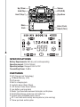
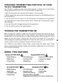
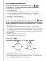
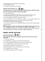
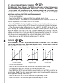
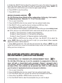
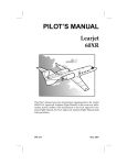
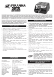
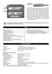
USER MANUAL TABLE OF CONTENTS INTRODUCTION . . . . . . . . . . . . . . . . . . . . . . . . . . . . . . . . . . . . . . . . 3 WARRANTY SERVICE . . . . . . . . . . . . . . . . . . . . . . . . . . . . . . . . . . . 3 PRECAUTIONS AND SAFETY . . . . . . . . . . . . . . . . . . . . . . . . . . . . 3 SPECIFICATIONS . . . . . . . . . . . . . . . . . . . . . . . . . . . . . . . . . . . . . . . 4 TURNING THE TRANSMITTER ON . . . . . . . . . . . . . . . . . . . . . . . . 5 MODEL TYPE FEATURES . . . . . . . . . . . . . . . . . . . . . . . . . . . . . . . . 5 SYSTEM SETUP FUNCTIONS Model Memory. . . . . . . . . . . . . . . . . . . . . . . . . . . . . . . . . . . . . . . . . . . . 5 Model Type . . . . . . . . . . . . . . . . . . . . . . . . . . . . . . . . . . . . . . . . . . . . . . 6 Swash Type . . . . . . . . . . . . . . . . . . . . . . . . . . . . . . . . . . . . . . . . . . . . . . 6 Range Check . . . . . . . . . . . . . . . . . . . . . . . . . . . . . . . . . . . . . . . . . . . . . 6 MODEL SETUP OPTIONS Servo Reversing . . . . . . . . . . . . . . . . . . . . . . . . . . . . . . . . . . . . . . . . . . . 7 ATV . . . . . . . . . . . . . . . . . . . . . . . . . . . . . . . . . . . . . . . . . . . . . . . . . . . 7 2 Curve/s . . . . . . . . . . . . . . . . . . . . . . . . . . . . . . . . . . . . . . . . . . . . . . . . . 8 Sub Trim . . . . . . . . . . . . . . . . . . . . . . . . . . . . . . . . . . . . . . . . . . . . . . . . 8 AIRPLANE SPECIFIC OPTIONS AND ADJUSTMENTS Flap . . . . . . . . . . . . . . . . . . . . . . . . . . . . . . . . . . . . . . . . . . . . . . . . . . . 9 Gear Speed . . . . . . . . . . . . . . . . . . . . . . . . . . . . . . . . . . . . . . . . . . . . . . 9 Mixing . . . . . . . . . . . . . . . . . . . . . . . . . . . . . . . . . . . . . . . . . . . . . . . . . 9 HELICOPTER SPECIFIC OPTIONS AND ADJUSTMENTS CCPM Mixing . . . . . . . . . . . . . . . . . . . . . . . . . . . . . . . . . . . . . . . . . . . . .10 Gyro Gain . . . . . . . . . . . . . . . . . . . . . . . . . . . . . . . . . . . . . . . . . . . . . . .11 Throttle Hold . . . . . . . . . . . . . . . . . . . . . . . . . . . . . . . . . . . . . . . . . . . . .11 ATS.MIX . . . . . . . . . . . . . . . . . . . . . . . . . . . . . . . . . . . . . . . . . . . . . . . .11 UP-1 Pitch Curve . . . . . . . . . . . . . . . . . . . . . . . . . . . . . . . . . . . . . . . . . .12 Adjusting the Throttle Curve in Normal . . . . . . . . . . . . . . . . . . . . . . . . . . .12 Adjusting the UP-1 Throttle Curve . . . . . . . . . . . . . . . . . . . . . . . . . . . . . . .13 TRAINER SYSTEM . . . . . . . . . . . . . . . . . . . . . . . . . . . . . . . . . . . . . .13 SYSTEM RESET . . . . . . . . . . . . . . . . . . . . . . . . . . . . . . . . . . . . . . . .14 MODE 1 VS MODE 2 . . . . . . . . . . . . . . . . . . . . . . . . . . . . . . . . . . . . .15 INTRODUCTION Thank you for purchasing the TX610 digital proportional R/C airplane/helicopter transmitter. The TX610 computer transmitter can be used to control model airplanes as well as model helicopters. It employs advanced 2.4GHz communication technology. In order to make the best use of your TX610 and to operate it safely, please read all of the instructions. MANUAL SPECIFICATIONS AND DESCRIPTION CHANGES All pictures, descriptions, and specifications found in this instruction manual are subject to change without notice. Hobbico maintains no responsibility for inadvertent errors in this manual. WARRANTY SERVICE We will warrant your TX610 90 days after the purchase from defects in materials or workmanship of original manufacture. We will at our option, repair or replace at no charge, the incorrectly made part. This warranty does not cover damage caused by crash, abuse, misuse, alteration or accident. To return your radio for service you need to provide proof of purchase. Your store receipt or product invoice will suffice. IN NO EVENT SHALL THE PURCHASER BE ENTITLED TO ANY INCIDENTAL, SPECIAL, INDIRECT OR CONSEQUENTIAL DAMAGES, WHETHER RESULTING FROM THE USE, MISUSE OR INABILITY TO USE THE PRODUCT OR FROM DEFECTS IN THE PRODUCT. This warranty gives you specific legal rights and you may also have other rights, which vary from state to state. Outside USA and Canada, contact local importer for warranty information. Hobby Services 3002 N. Apollo Drive, Suite 1 Champaign, Illinois 61822 Attn: Service Department Phone: (217) 398-0007 9:00 am - 5:00 pm Central Time M-F E-mail: [email protected] PRECAUTIONS AND SAFETY If there are any special regulations for using 2.4GHz radio systems at your flying site, please obey all regulations. 2.4GHz is very different than frequencies of the past. Please keep the model in sight at all times as large objects can block the RF signal. Also keep in mind that objects such as wire fences and wire mesh might also cause signal loss. NEVER grip or shroud the transmitter antenna when flying as this degrades RF quality and could cause loss of control. 3 Up-1/Gear Hold/Flap Trainer ATV (D/R) Hov.T/Flap.T Gyro/Gear Mode Back 4 SPECIFICATIONS Battery Requirements: 8AA dry cell (sold separately) Operating current: 100 to 150mH Operating voltage: Range of 8.5V to 13V Transmitting Power: 2+dBm FEATURES • SLT (Secure Link Technology) • 10 Model Memory (0-9) • 6 Channels • Built in charging jack • Inactivity alarm (9min 30sec) • LCD Screen Power Saver feature • Low battery warning alarm • Model Type Selectable between Helicopter and Airplane • Switchable between mode one and mode two • System setup and Model setup menus • UP-1 and hold switch safety warning alarms (mix warning) • Trainer port and switch option Enter (Push) Adjust (Turn) CHANGING TRANSMITTING PROTOCOL OF YOUR TX-610 TRANSMITTER Your TX-610 is capable of using Tactic brand receivers. In doing so one must simply change protocols from R-0 to R-1 in the transmitters programing. 1. With the transmitter off, place the HOLD switch in the on position. 2. While holding the trainer switch forward and pressing down on the MODE button turn the transmitter on. 3. You will see R-0 or R-1 flash in in the LCD screen. R-0 allows you to fly products not supported with a Tactic brand receiver and R-1 allows you to fly products using a Tactic Receiver. 4. Use the D/R switch to toggle between the two selections. 5. Turn the HOLD switch off to begin operation. TURNING THE TRANSMITTER ON When turning your TX610 on, make sure the switches located near and at the top of the transmitter are switched into the “back” position. Also make sure the transmitters throttle stick is in the low position or a safety warning alarm will sound and a T-H will appear on the LCD screen. Lowering the stick will turn the alarm off. If you hear a warning beep and see the icons either 3D or T-H on the LCD screen, you have the UP-1 switch or HOLD switches activated. Please turn them off (back). Your TX610 has two different setup modes, system setup and model setup. These menus change slightly between airplane and helicopter model types so we will outline the two types individually. MODEL TYPE FEATURES Airplane SYSTEM SETUP s Model Memory s Model Type s Range Check Heli SYSTEM SETUP s Model Memory s Model Type s Swashplate Type s Range Check Airplane MODEL SETUP s Servo Reversing s Dual Rate (D/R) s Wing Mixing s Exponential Curve (EXPO) s Landing Gear Speed s Sub Trim Heli MODEL SETUP s Servo Reversing s Gyro Gain s Dual Rate (D/R) s Throttle Hold s CCPM Swash Mixing s Sub Trim s Revolution Mixing (ATS.MIX) s Exponential Curve (EXPO), Pitch Curve, Throttle Curve 5 SYSTEM SETUP FUNCTION MODEL MEMORY (SWITCHING BETWEEN MODELS) You may have up to 10 models (airplane and/or helicopter) stored into your transmitter. (Models 0 through 9). 1. Turn the transmitter on. 2. Hold both buttons MODE and BACK down for one second for system setup. 3. Press the ENTER button and the model number itself will continue to flash. 4. Turn the ADJUST dial either clockwise or counterclockwise to scroll between models. 5. Press ENTER to accept your selection. 6. Press BACK to escape and save the setting. 6 MODEL TYPE (SWITCHING BETWEEN PLANE & HELI MODE) The TX610 allows you to have both airplane and helicopter model types setup into your transmitter. Models 0 thought 9 could be either airplane or helicopter or a mix of both. 1. Turn the transmitter on. 2. Hold both buttons MODE and BACK down for one second for system setup. 3. Turn the ADJUST dial clockwise to enter airplane/helicopter selection mode (icon will flash). 4. Press button MODE or ENTER to select the mode icon itself. It will continue to flash. 5. Turn the ADJUST dial either clockwise or counterclockwise to scroll between airplane or helicopter mode. 6. Press MODE or ENTER to enter your selection. 7. Press BACK to escape and save the setting. SWASH TYPE This is used to select between a 90° or 120° swash arrangement. Elevator Elevator 90° 120° Aileron Pitch Mechanical Mixing Aileron Electronic Mixing (CCPM ) 1. Turn the transmitter on. 2. Hold both buttons MODE and BACK down for one second for system setup. 3. Turn the ADJUST dial until you see the swash ring type icon, and MODE icon flash. 4. Press either MODE or ENTER to activate the selection. 5. Rotate ADJUST to scroll between the two options. 6. Push ENTER to accept. 7. Press BACK to exit and save the setting. RANGE CHECK MODE (P-H) This allows the user to ground test the range of the radio system. (NOTE: Do not fly the model with the transmitter in Range Check Mode) 1. Turn the transmitter on. 2. Hold both buttons MODE and BACK down for one second for system setup. 3. Dial the ADJUST dial until you see the P-H (Power-High) icon flash. 4. Press either MODE or ENTER to enter power mode. 5. Turn the ADJUST dial to scroll between H (high) and L (low) power options (the transmitter will beep letting you know you are in the low power mode). 6. Press BACK to escape and save the setting. 7. To end, cycle the power switch (WARNING: Make sure the model is inactive before cycling the power). NOTE: Each time you turn the transmitter on it will automatically come on in high power mode. WARNING: DO NOT FLY THE MODEL IN RANGE CHECK MODE! This is for ground checking the model only! (In low power mode, you should be able to maintain a radio connection to your model at a distance of 90 feet [28meters]). MODEL SETUP OPTIONS SERVO REVERSING Servo reversing allows you to change the travel direction of the servo from the transmitter. 1. Turn on the transmitter. 2. Press MODE for one second. You have entered model setup. 3. Press either MODE or ENTER to enter the channel selection mode. 4. Turn the ADJUST dial to select between channel numbers. 5. Press MODE or ENTER to activate the menu. 6. Rotate the ADJUST dial to scroll between normal or reverse. 7. Press ENTER to save the setting. 8. Press BACK to escape and exit the program. 7 ATV (ADJUSTABLE TRAVEL VOLUME) ATV (Adjustable Travel Volume): The TX610 is quite unique in that it allows servo rate travel and end point adjustments from -125% to +125% on channels 1, 2 and 4 in one menu. This system also allows a switchable high-low rate volume (D/R Switch) with adjustable end points. Keep in mind when setting up the dual rate (D/R) switch; one needs to adjust both transitional end-points. 1. Turn on the transmitter. 2. Press button MODE for one second. You have entered model setup. 3. Rotate the ADJUST dial clockwise until you see the channel numbers as well as the dual rate ellipse flash in the lower center of the screen. 4. Press the ENTER button to select the channel you wish to change. As you can see you can continue to press button ENTER to select and auto scroll through the channels. 5. When the value number is flashing you can rotate the ADJUST dial to adjust the value. Moving the D/R switch between the forward and back position allows you to adjust the value in either high or low rate. (Typically forward switch position is low rate and back switch position is high rate). Moving the control stick fore and aft or left and right allows you to see and adjust the end point adjustment within the rate. 6. When done use the BACK button to exit and save the settings. 8 CURVE/S EXPO Channels 1, 2, and 4. - 5 point throttle curve on Channel 3. NOTE: The TX610 also has a 5 point pitch curve on Channel 6 (HELI ONLY). We will cover this in the Helicopter Section of the manual. 100% 0% 100% 100% 0% 100% 100% 0% 100% 100% 0% 100% 100% 0% 100% 100% 0% 100% Linear Reaction Negative Expo Positive Expo 1. Turn on the transmitter. 2. Press the MODE button for one second. You have entered model setup. 3. Turn the ADJUST dial until you see just the channel icons flash. 4. Press MODE or ENTER and just the first adjustable channel will flash as well as the current value. (Note: If no value percentage is being used, you will see 00E, meaning no percentage value is being used in EXPO.) 5. Press the MODE or ENTER button to activate the percentage value. 6. Rotate the ADJUST dial to either a positive value or negative value. 7. Press the ENTER button to save and move to the next channel (you may also dial (D) after pressing ENTER to expedite your selections). 8. NOTE: Channel 3 will show the icon “dot”. Pressing ENTER allows a 5 point throttle curve in both airplane and helicopter modes. Simply scroll, press ENTER and dial in a new value for each point (dot) of the curve. (ALSO NOTE: When a helicopter model is setup or chosen you also have access to a 5 point pitch curve on Channel 6. We will talk more about that in the Helicopter specific section. 9. Press the BACK button to exit and save the settings. SUB TRIM (CHANNELS 1, 2, 4) Sub trim is used to center a servo arm within the programming. NOTE: Most heading hold gyro systems including TAG systems don’t respond well to trim or sub-trim changes. It is best to have sub trims set at 0 when using heading hold stabilization systems. 1. Turn on the transmitter. 2. Press button MODE for one second. You have entered model setup. 3. Turn the ADJUST dial until you see the channel trim boxes flash on Channels 1, 2 and 4 (it will be the last flashing menu when using the dial). 4. Press ENTER to enter this option. 5. Dial ADJUST to scroll between the three channels. 6. Press ENTER to activate the channel. 7. Rotate the ADJUST dial to change the value. 8. Press BACK to escape and save the setting. AIRPLANE SPECIFIC OPTIONS AND ADJUSTMENTS (AIRPLANE MODE) FLAP SWITCH The flap switch can be used a few different ways. One turns on or actuates the flaps by flipping the switch down. Depending on the position of the flap trim dial the flaps will deploy to that setting. OR, one can adjust the servo linkage such that with the flap switch ON/DOWN, the user dials in the amount of flap deflection desired using the HOV.T/FLAP.T dial. GEAR SPEED: (SLOWING DOWN A RETRACT SERVO) The TX610 allows you to adjust the transit speed to channel 5 servo (landing gear). You may adjust different speeds for both up and down. 1. Turn on your transmitter. 2. Press the MODE button for one second. You have entered model setup. 3. Turn the ADJUST dial until you see the G-S icon flash. 4. Press MODE or ENTER and the setting value will flash. 9 5. Rotate the ADJUST dial to adjust the speed of the servo (the higher the value the faster the transit speed, and lower the value the slower the transit speed). NOTE: The two position G.S switch allows you to have two gear speed settings. 6. Press ENTER to save the setting. 7. Press BACK to exit. 10 MIXING (CHANNEL MIXING) The TX 610 allows three different mixing configurations: Delta wing, V-tail control, and flaperon/spoileron. Channels 1-2, 2-4 or 1-6 can be mixed. 1. Turn on your transmitter. 2. Press the MODE button for one second. You have entered model setup. 3. Dial ADJUST until you see the channel numbers and MIX icon flash. 4. Press MODE or ENTER and just the MIX will flash. 5. Turn the ADJUST dial and option 1 and the MIX will flash letting you know mixing is now on. At this point you can rotate ADJUST dial to select what channel sets you wish to mix. Number 1 mixes Channels 1-2, delta wing configuration Number 2 mixes Channels 2-4, V-tail control configuration Number 3 mixes Channels 1-6. flaperon/spoileron configuration 6. Press MODE or ENTER and the values will flash. Use ADJUST (D) to adjust the values. NOTE: Moving the stick from left to right (or up and down) allows separate adjustment values to either direction. 7. Press BACK to back out. This will also exit and save the settings. (NOTE: You will notice that the MIX icon, as well as the selected mixing number, will remain illuminated, letting you know mixing is on. HELICOPTER SPECIFIC OPTIONS AND ADJUSTMENTS (HELICOPTER MODE) CCPM MIXING: (120° SWASHPLATE ARRANGEMENT ONLY) The Heli-Max 610 allows you to mix the swashplate to compensate for either updown, left-right, or forward-back cyclic commands. Channel 1 represents side to side (aileron), Channel 2 represents forward and back (elevator) and Channel 3 up and down (Pitch). Each selection can be adjusted from -100% to +100% allowing you full control of swashplate direction and amount of deflection. 1. Turn on your transmitter. 2. Press the MODE button for one second. You have entered model setup. 3. Turn the ADJUST dial until you see the channel and swashplate icons flash. 4. Press either the MODE or ENTER button to enter this menu. 5. Turn the ADJUST dial to select the swashplate mix you want to adjust. 6. Press either the MODE or ENTER button. The channel mixing selection, 1, 2 or 3 (see selection information above), as well as the swashplate icon will flash. 7. Turn the ADJUST dial to adjust the value, note either a + or – value and the relationship they have on direction. It’s also important to note that these values also dictate total deflection volume. The higher the value, the more travel the selection will move. 8. Press MODE or ENTER to accept the changes. 9. Press BACK to exit the menu. Hea di GYRO GAIN Allows for both heading hold and non-heading hold flight conditions. 1. Turn on your transmitter. 2. Press the MODE button for one second. You have entered model setup. 3. Turn the ADJUST dial until you see the G-S icon flash. ld Ho 100% 4. Push either the MODE or ENTER button to activate the selection. ng 50% 100% 5. The value will flash based on the G.S switch position. 75% 6. A value of over 50% engages heading hold and a value of below 0% 50% 50% non-heading hold. The values also dictate gyro sensitivity. Values closest to 0% (N-HH) and 100% (HH) represent the MOST sensitivity 25% 0% 50% and values closed to 50% (i.e. 49% (N-HH, and 51% HH) the least. di 100% ng 7. Use the ADJUST dial to adjust the value. Hol d 8. Press the BACK button to exit and save the settings. N on -H e a THROTTLE HOLD This feature presets a throttle position without affecting pitch. 1. Turn on your transmitter. 2. Press the MODE button for one second. You have entered model setup. 3. Turn the ADJUST dial until you see the TH icon flash. 4. Push either the MODE or ENTER button to activate the selection. 5. Use the ADJUST dial to adjust the value. (NOTE: On an electric powered helicopter this will enable the motor controller, causing the motor to turn. On electric helicopters a value of 000 is your safest option). 6. Press the BACK button to exit and save the settings. ATS.MIX (REVOLUTION MIXING) Only used with non-heading hold gyros. 1. Turn on your transmitter. 2. Press the MODE button for one second. You have entered model setup. 3. Turn the ADJUST dial until you see the channel numbers as well as the MIX icon flash 4. Press ENTER to turn on the feature. 11 5. Rotate the ADJUST DIAL to turn the MIX feature ON (Channel 1 flashing) or OFF (Channel 1 hidden). 6. Press ENTER again to enter the channel MIX menu. You will see the Channels 3 and 4 flashing. 7. Rotate the ADJUST dial to select which channel you want to adjust, Channel 3 or 4. 8. Press ENTER to prepare to adjust the channel. 9. Turn the ADJUST dial to set the value/s. 10. Press the BACK button to continue or exit and save the settings. Throttle/Pitch Stick Movement 12 ADJUSTING THE PITCH CURVES You can adjust the UP-1 pitch curve (some call this “Stunt Mode”). This curve allows you to adjust the pitch range and placement of the pitch curve necessary for flips, rolls and inverted flight. 1. Turn on your transmitter. 2. Press the MODE button for one second. You have entered model setup. 3. Turn the ADJUST dial until you see just the channel icons flash. 4. Press MODE or ENTER and just the first adjustable channel will flash as well as the current value. 5. Turn the ADJUST dial until you reach Channel 6. The channel number will flash with dot below. 6. Press the MODE or ENTER button to activate the percentage value. 7. Rotate the ADJUST dial to scroll through the 5 dot points. 8. To adjust “Normal Mode”, place the HOLD/FLAP switch in the upper position. To adjust the “UP-1 Mode”, place the HOLD/FLAP switch in the lower position. 9. Press Mode or ENTER buttons to select (flashing) dot percentage you wish to change. 10. Press ENTER to save and move to the next dot. You may also use the ADJUST dial after pressing ENTER to expedite your selections. 11. To exit, press BACK to save and close. Typical "Normal Mode" 5 Point Pitch Curve 100% Modified "UP-1" 5 Point Pitch Curve 100% 4 50% 2 100% 5 5 3 50% 50% 50% 1 0% Pitch Points (dot ) 3 2 1 0% 100% 4 0% 0% Pitch Points (dot ) ADJUSTING THE THROTTLE CURVE IN NORMAL The throttle curve can be adjusted to optimize the power to the motor depending on stick position and blade load. 1. Turn on your transmitter. 2. Press the MODE button for one second. You have entered model setup. 3. Turn the ADJUST dial until you see just the channel icons flash. 4. Press MODE or ENTER and just the first adjustable channel will flash as well as the current value. 5. Turn the ADJUST dial until you reach Channel 3. The channel number will flash with dot below. 6. Press the MODE or ENTER button to activate the percentage value. 7. Rotate the ADJUST dial to scroll through the 5 dot points. 8. Press Mode or ENTER buttons to select (flashing) dot percentage you wish to change. 9. Press ENTER to save and move to the next dot. You may also use the ADJUST dial after pressing ENTER to expedite your selections. 10. To exit, press BACK to save and close. ADJUSTING THE UP-1 THROTTLE CURVE NOTE: The UP-1 Throttle curve is preset at the factory. Having said this you can use the HOV.T/FALP.T dial to adjust the UP-1 throttle curve from 51% to 100% power while the UP-1 switch is on. To better explain the throttle curves let’s review the diagrams below. In the figure you can see three throttle curves. The one to the left is a typical throttle curve with the helicopter operating in normal mode. (The UP-1 switch off) The picture in the center shows the throttle curve with the transmitters UP-1 switch ON and the HOV.T/ FALP.T dial turned fully counter clockwise. The picture on the right shows the same condition with the HOV.T/FLAP.T dial turned fully clock wise. (This setting provides the most power to the motor with the UP-1 switch active.) 13 Throttle/Pitch Stick Movement Possible "UP-1" Throttle Modes Typical "Normal Mode" 5 Point Throttle Curve 100% 100% 5 HOV.T/FLAP.T Rotate Dial Counter Clockwise 100% 1 5 100% 4 50% 3 2 50% 50% HOV.T/FLAP.T Rotate Dial Clockwise 100% 1 2 3 4 5 100% 4 3 50% 50% 0% 0% 50% 2 0% 1 0% Throttle Points (dot ) 0% Throttle Points (dot ) 0% Throttle Points (dot ) TRAINER SYSTEM Make sure the instructor’s transmitter is properly bound to the model, and the instructor’s transmitter, student’s transmitter and helicopter are not powered on. 1. Connect the trainer cord to the instructor and student’s transmitter via the plug in sockets located on the back of the transmitters. (The model must have the same setup parameters in both transmitters) 2. Power on the student transmitter. 3. Power on the instructor’s transmitter. 4. Power up the helicopter. 5. The instructor’s transmitter will now have control of the helicopter. 6. Flip forward and hold the trainer switch to allow the student control. Relaxing switch pressure and the instructor resumes control. SYSTEM RESET WARNING: This action will cause all modified models and programming to revert to factory defaults. Press MODE, BACK and ENTER at the same time and then turn the transmitter ON. Momentarily the transmitter will beep and all programming will be reset to default. Here are the default settings to your transmitter: 14 AIRPLANE Servo Reversing: Normal (ALL) D/R Aileron: High 100% low 80% D/R Elevator: High 100% low 80% D/R Rudder: High 100% low 80% EXPO Aileron: 0 EXPO Elevator: 0 Throttle Curve: dot 1 (0%), dot 2 (25%), dot 3 (50%), dot 4 (75%), dot 5 (100%) Expo Rudder: 0 Gear Speed Slow: 25%, Fast 75% Wing Mixing: OFF HELICOPTER Swash Arrangement: 90° mechanical Servo Reversing: Normal (ALL) D/R Aileron: High 100% low 80% D/R Rudder: High 100% low 80% D/R Elevator: High 100% low 80% Revolution Mixing: OFF EXPO Aileron: 0 EXPO Elevator: 0 Throttle Curve: dot 1 (0%), dot 2 (25%), dot 3 (50%), dot 4 (75%), dot 5 (100%) Expo Rudder: 0 Pitch Curve: dot 1 (35%), dot 2 (45%), dot 3 (55%), dot 4 (65%), dot 5 (75%) UP-1 Pitch Curve: dot 1 (30%), dot 2 (42%), dot 3 (55%), dot 4 (65%), dot 5 (75%) Gyro: Switch position back (25% nonheading hold) Switch position forward (75% heading hold) Throttle Hold: 0% MODE 1 VS. MODE 2 Below are the two major differences between mode 1 and mode 2. Mode 1 has the Throttle and Aileron on the right stick. The Elevator and Rudder are on the left stick. Mode 2 has the Aileron and Elevator, the two main controls, on the right stick. The Throttle and Rudder are on the left stick. This is how your TX610 comes delivered from the factory. To change from Mode 2 to Mode 1, simply remove the small center cover from the back of the transmitter and position the switch to your liking. Replace the cover. You will note the throttle stick reverts to the right side of the transmitter in mode one. MODEL TYPE NAME 0 1 2 15 3 4 5 6 7 8 9 FCC REQUIREMENT This device complies with part 15 of the FCC rules. Operation is subject to the following two conditions. (1) This device may not cause harmful interference. (2) This device must accept any interference received, including interference that may cause undesired operation. NOTE: THE MANUFACTURER IS NOT RESPONSIBLE FOR ANY RADIO OR TV INTERFERENCE CAUSED BY UNAUTHORIZED MODIFICATIONS TO THIS EQUIPMENT. SUCH MODIFICATIONS COULD VOID THE USER’S AUTHORITY TO OPERATE THE EQUIPMENT. CE COMPLIANCE INFORMATION FOR THE EUROPEAN UNION Instructions for Disposal of Waste Equipment by Private Users in the European Union: This symbol on the product or its packaging indicates this product must not be disposed of with other household waste. Instead, it is the user’s responsibility to dispose of their waste equipment by handing it over to a designated collection point for the recycling of waste electrical and electronic equipment. The separate collection and recycling of your waste equipment at the time of disposal will help to conserve natural resources and ensure that it is recycled in a manner that protects human health and the environment. For more information about where you can drop off your waste equipment for recycling, please contact your local city office, your household waste disposal service or location where you purchased the product. Declaration of Conformity: Product: Heli-Max TX610 2.4GHz 6-Channel Tx Rx Item number: HMXJ2025 TX610, Equipment class: 1 TX610 transmitter: The objects of the declaration described here are in conformity with the requirements of the specifications listed below, following the provisions of the European 2006/95/EC Low Voltage Directive: EN 60950-1:2006 Safety The objects of the declaration described here are in conformity with the requirements of the specifications listed below, following the provisions of the European R&TTE directive 1995/5/EC: ETSI EN 300 328 V1.7.1 Technical requirements for radio equipment ETSI EN 301 489-1 V1.8.1, 301 489-17 V1.3.2 General EMC requirements for radio equipment Hobbico, Inc. 2904 Research Road Champaign, IL USA 61826 2200 The associated regulatory agencies of the following countries recognize the noted certifications to this product as authorized for sale and use. UK DE DK BG SE FI GR EE LV LT PL CZ SK HU RO SI AT IT ES PT IE NL LU MT CY HMXJ2025 Mnl v1.0 © 2012 Hobbico, Inc. All rights reserved.