1
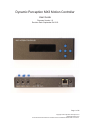
Dynamic Perception MX3 Motion Controller
User Guide
Firmware Version 1.0
Revision Date: September 5th 2013
Page 1 of 45
Copyright © 2013 Dynamic Perception LLC
dynamicperception.com
All Contents licensed under the Creative Commons Attribution Share-Alike 3.0 License
FCC Compliance
This device complies with part 15 of the FCC Rules. Operation is subject to the following two conditions:
(1) This device may not cause harmful interference, and
(2) this device must accept any interference received, including interference that may cause undesired
operation.
This equipment has been tested and found to comply with the limits for a Class B digital device, pursuant to
part 15 of the FCC Rules. These limits are designed to provide reasonable protection against harmful
interference in a residential installation. This equipment generates, uses and can radiate radio frequency
energy and, if not installed and used in accordance with the instructions, may cause harmful interference to
radio communications. However, there is no guarantee that interference will not occur in a particular
installation. If this equipment does cause harmful interference to radio or television reception, which can be
determined by turning the equipment off and on, the user is encouraged to try to correct the interference by
one or more of the following measures:
●
●
●
Reorient or relocate the receiving antenna.
Increase the separation between the equipment and receiver.
Connect the equipment into an outlet on a circuit different from that to which the receiver is
connected. Consult the dealer or an experienced radio/TV technician for help
Page 2 of 45
Copyright © 2013 Dynamic Perception LLC
dynamicperception.com
All Contents licensed under the Creative Commons Attribution Share-Alike 3.0 License
Table of Contents
1. Specifications
2. Overview
3. Basic Operation
3.1. Powering the MX3
3.1.1. DC Input Jack
3.1.2. MoCoBus Connector
3.1.3. USB Connector
3.2. Buttons
3.2 Control Screens
3.4 Accessing Menus
4. Main Control Screens
4.1. Program Control
4.2. Camera Control
4.3. Motor Control
5. Main System Menu
6. Camera Control
6.1. Connecting the Camera
6.2. Introduction to the MX3 Camera Cycle
6.3. Controlling Exposure on the Camera
6.4. Controlling Exposure on the MX3
6.5. Controlling Focus, Waking Camera up from Sleep
6.6. Multiple Exposures
6.7. Focus Lock with Shutter
6.8. Limiting Total Shots
6.9. Full Manual Camera Control
7. Motion Control
7.1. Configuring Motor Axes
7.1.1. Configure Axis Using Presets
7.1.2. Configure Axis Manually
7.2. Choosing Your Motion Mode
7.3. Continuous Motion
7.4. Shoot-Move-Shoot Motion
7.5. Lead-In and Out
7.6. Linear Ramping
7.6.1. Symmetric Ramping
7.6.2. Asymmetric Ramping
7.7. Manual Motor Control
7.8. Swapping Directions
Page 3 of 45
Copyright © 2013 Dynamic Perception LLC
dynamicperception.com
All Contents licensed under the Creative Commons Attribution Share-Alike 3.0 License
8. Warnings and Alarms
8.1. Input Voltage Alarm
8.2. Motor Current Alarm
8.3. Motor Temperature Alarm
9. Auxiliary Inputs and Outputs
9.1. Auxiliary I/O Technical Details
9.2. Input Program Actions
9.2.1. Changing the Input Trigger Type
9.3. Output Program Actions
9.3.1. Output Before Exposure
9.3.2. Out After Exposure
9.3.3. Changing the Output Level
9.4. Common Use-Cases
9.4.1. Limit Switches
9.4.2. External Intervalometer
9.4.3. “Chasing the Shutter”
10. Cold Weather Modification
11. System Settings
11.1. Metric Display
11.1. LCD Backlight Auto-Off
11.2. Reset to Factory Defaults
11.3. Motor Timing
12. Updating Firmware
13. Trouble Shooting
Appendix A: Menu Tree
Appendix B: List of Supported Cameras
Page 4 of 45
Copyright © 2013 Dynamic Perception LLC
dynamicperception.com
All Contents licensed under the Creative Commons Attribution Share-Alike 3.0 License
1. Specifications
Operating Parameters
Temperature Range (Standard)
0C - 80C (32F - 176F)
Temperature Range (Cold Weather Upgrade)
-20C - 80C (-4F - 176F)
Maximum Relative Humidity
90% non-condensing
Camera
3/32” (2.3mm) TRS
I/O Ports
2x 3/32” (2.3mm) TRS
DC Input
2.1 x 5.5mm DC barrel (+)-
Motor Output
3x 2.5 x 5.5mm DC barrel
USB
USB Micro B
MoCoBusTM
RJ-45 Female
Input Voltage (DC Jack)
8VDC - 24VDC
Input Voltage (USB)
5VDC
Input Voltage (MoCoBusTM)
12VDC - 24VDC
Maximum Current (DC Jack)
5A
Maximum Current (USB)
500mA
Maximum Current (MoCoBusTM)
1A
Supported Motor Type
DC Brushed Motor
Maximum Current Draw
2A (ea. motor, not to exceed power
source maximum)
Firmware
GPLv3
Schematics and Board Design
Creative Commons Attribution
Share-Alike 3.0
Ports
Electrical Characteristics
Motor Outputs
License
Page 5 of 45
Copyright © 2013 Dynamic Perception LLC
dynamicperception.com
All Contents licensed under the Creative Commons Attribution Share-Alike 3.0 License
2. Overview
--The MX3 is an open-source 3-axis time-lapse motion controller with integrated camera control,
multiple device connectivity, and MoCoBusTM support. Built to the highest specification with
industrial grade components, the MX3 is designed to provide years of reliable operation in the
field, wherever your photography takes you.
--The MX3 provides a simple, intuitive means for specifying continuous and shoot-move-shoot
motion-controlled time-lapse videos automatically, using inexpensive DC motors for up to three
axes of control.
--Auxiliary input and output ports allow you to integrate with limit switches and other devices for
more expressive automation in the studio or in the field.
--Cold weather versions expand the operating temperature range for winter shooting in very cold
climates.
--MoCoBusTM support allows for future expansion of the firmware to control MoCoBusTM enabled
devices without a computer.
--Camera control integration automates control over dozens of popular camera models.
--Powerful, industrial-class motor drives combined with a wide input voltage range allow for
control of nearly any common DC brushed motor and for large payloads.
--Automated alarms monitor battery voltage, internal temperature, and motor current draw to
automatically alert on, and reduce the possibility of equipment damage.
Page 6 of 45
Copyright © 2013 Dynamic Perception LLC
dynamicperception.com
All Contents licensed under the Creative Commons Attribution Share-Alike 3.0 License
3. Basic Operation
The MX3 user interface consists of a 2x16 LCD display and five user input buttons. Upon
startup, the firmware version will be reported before going to the main control screens.
3.1. Powering the MX3
The MX3 can accept several different power sources. The primary sources for power are the
DC input jack, the USB connector, and the MoCoBus port. For typical use-cases, you will likely
use the DC input jack.
3.1.1. DC Input Jack
The DC input jack is the primary power source for most motion control operations. This is the
only power source that will let you run the DC motor drivers. You can connect a battery, or AC
adapter using a 2.0mm DC barrel connector.
The DC input jack accepts a wide range of voltages, from 8VDC to 24VDC. Whatever voltage is
provided via the DC input jack is the voltage the motors will be run at.
Do not supply more voltage via the DC input jack than your motors can handle. This
will result in permanent damage to your motors. Check the rating on your motors
before connecting them and verify they can support the supply voltage you ar
providing.
Do not attach two motors with different voltage requirements at the same time. The
MX3 can provide only a single output voltage to all motors.
3.1.2. MoCoBus Connector
The MX3 can be powered via MoCoBus when running as a MoCoBus controller. The motor
drivers will be disabled when the only power source is the MoCoBus connector, as MoCoBus
cannot provide enough power to run DC motors. You may connect the DC input jack and the
MoCoBus connector at the same time as long as they are running at the same voltage.
Page 7 of 45
Copyright © 2013 Dynamic Perception LLC
dynamicperception.com
All Contents licensed under the Creative Commons Attribution Share-Alike 3.0 License
Do not connect a power source to the DC input jack while the MoCoBus connector is
in-use if the power source is running at a different voltage than the MoCoBus.
3.1.3. USB Connector
The USB connector can be used when connected to a computer or a powered hub, for powering
the MX3 alone. This can be useful for setting up the MX3, or using it as an intervalometer alone.
Motors cannot be used with USB power, this 5V source is not enough power to drive
motors. The controller will reset if motors are turned on under USB power.
Page 8 of 45
Copyright © 2013 Dynamic Perception LLC
dynamicperception.com
All Contents licensed under the Creative Commons Attribution Share-Alike 3.0 License
3.2. Buttons
Each button may have special purpose depending on user activity, however, the general
functionality of each button is specified below:
1. [Up]
a. Increase value
b. Go up in menu
c. Change control screen
2. [Down]
a. Decrease value
b. Go down in menu
c. Change control screen
3. [Left]
a. Go back one step, close menu
b. Select previous control
c. Abort input
4. [Right]
a. Go forward one step, open menu
b. Select next control
c. Save Input
5. [Enter]
a. Open menu
b. Save input
Page 9 of 45
Copyright © 2013 Dynamic Perception LLC
dynamicperception.com
All Contents licensed under the Creative Commons Attribution Share-Alike 3.0 License
3.2 Control Screens
There are five main control screens:
1.
2.
3.
4.
5.
Program Control
Camera Control
Motor 1 Control
Motor 2 Control
Motor 3 Control
You may switch screens by pressing the [Up] and [Down] buttons, as long as no control on that
screen is selected. To select a control on a screen, first press [Right] to access the first
available control on that screen. Afterwards, pressing [Right] or [Left] switches between
available controls. Once a control is selected, use [Up] and [Down] to change the value of that
control. To stop selecting a control press [Left] or [Right] until no control is highlighted.
More details on the available controls are available in the Main Control Screens section below.
3.4 Accessing Menus
To access the Main System Menu, press [Enter] on any control screen when no control is
selected. Some controls have specialized menus available to them. To access these menus,
press [Enter] while the control is selected. If the control does not have a specialized menu, the
[Enter] button will bring up the main system menu. Controls which have specialized menus are
documented in the Main Control Screens section below.
Page 10 of 45
Copyright © 2013 Dynamic Perception LLC
dynamicperception.com
All Contents licensed under the Creative Commons Attribution Share-Alike 3.0 License
4. Main Control Screens
The majority of your interaction with the MX3 will be through the main control screens, each of
these screens gives access to a number of parameters related to that screen. To change
control screens, simply press [Up] or [Down] while no control is selected to cycle through the
available screens.
4.1. Program Control
The Program Control screen controls the basic operation of the program, which executes your
time-lapse film. On this screen, we have control over whether the program is running (Off, or
On), the camera interval (in tenths of seconds), and the motion mode (Continuous or
Shoot-Move-Shoot). Additionally, the run time in hours, minutes, and seconds is displayed on
this screen.
For more information on Continuous and Shoot-Move-Shoot, see the Motion Control section below.
You may start or stop the program at any time through the on/off control, and may
change the interval control while the program is running. However, you may onl
change the motion mode when the program is stopped.
Page 11 of 45
Copyright © 2013 Dynamic Perception LLC
dynamicperception.com
All Contents licensed under the Creative Commons Attribution Share-Alike 3.0 License
4.2. Camera Control
The Camera Control screen controls the basic operations of the camera. On this screen, you
may control whether the exposure is controlled via the camera or via bulb, the bulb exposure or
camera exposure time, and any focus control time. Additionally, this screen displays whether or
not the camera is currently busy (taking an exposure, focusing, or performing some other
activity), and how many exposures have been triggered during the current program execution.
For more information on the camera controls available, and the possible values, see the Camera
Control section below.
Pressing [Enter] on any camera control will take you directly to the camera system
menu.
You can change any camera parameters while the program is running, and they will
take effect on the next shot.
Page 12 of 45
Copyright © 2013 Dynamic Perception LLC
dynamicperception.com
All Contents licensed under the Creative Commons Attribution Share-Alike 3.0 License
4.3. Motor Control
The Motor Control screens control the basic operation of each motor axis. On these screens,
you may control whether the motor is enabled, the direction of travel, the speed of travel, the
lead-in and lead-out amount, and the ramp-in/out amounts.
For more information on the controls available, see the Motion Control section below.
Pressing [Enter] on the Ramp control allows you to specify different ramp in and out
values, if you specify different values, ‘*’ will replace the ramp amount on the control
screen, indicating two values are in-use.
You can change any parameter while the program is running, unless the enable
status control reads ‘RMP’ indicating that a speed ramp is in progress.
Turning off a motor while a program is running will execute a speed ramp down
immediately if a down ramp value is specified.
Page 13 of 45
Copyright © 2013 Dynamic Perception LLC
dynamicperception.com
All Contents licensed under the Creative Commons Attribution Share-Alike 3.0 License
5. Main System Menu
The main system menu can be accessed at any time by pressing [Enter] on any control screen
without a control selected. All aspects of system operation can be configured from this menu.
You can navigate this menu using the five buttons, when navigating menus they have the
following functions:
●
●
●
●
●
[Left]
○ Go back one level
○ Exit menu (if on main system menu)
[Right]
○ Open sub-menu (if target is a menu)
○ Open edit value (if target is a parameter)
[Up]
○ Scroll to next item above
[Down]
○ Scroll to next item below
[Enter]
○ Open sub-menu (if target is a menu)
○ Open edit value (if target is a parameter)
On all menu screens and parameter edit screens, [Enter] and [Right] have the same
function.
The ‘>’ symbol will indicate which item is currently selected when on any menu.
Page 14 of 45
Copyright © 2013 Dynamic Perception LLC
dynamicperception.com
All Contents licensed under the Creative Commons Attribution Share-Alike 3.0 License
Within any menu there may be sub-menus and parameters to be edited. When pressing [Enter]
on any item, it will either open that sub-menu, or display a parameter edit screen. On the
parameter edit screen, the name of the parameter and value is displayed. When editing
parameters, the buttons have the following function:
●
●
●
●
●
[Left]
○ Cancel editing the parameter (Do not save changes)
[Up]
○ Increase value
[Down]
○ Decrease value
[Right]
○ Save current value to parameter
or [Enter]
○ Save current value to parameter
Some parameters will be numeric, and some will allow you to select from a list of options.
When editing a parameter, holding the [Up] or [Down] button for longer increases the
rate the value changes.
A menu navigation tree can be found in Appendix A: Menu Tree, individual menu
options are covered in detail by use-case in the sections below.
Page 15 of 45
Copyright © 2013 Dynamic Perception LLC
dynamicperception.com
All Contents licensed under the Creative Commons Attribution Share-Alike 3.0 License
6. Camera Control
The MX3 is capable of controlling a camera through its remote shutter port via the use of a
specialized 3/32” (2.3mm) TRS camera cable. If your camera does not have a remote shutter
port, it cannot be triggered with the MX3. You will need a specialized camera cable, available
from Dynamic Perception, for your specific camera.
For most cameras, the remote shutter port gives control over the focus trigger and
shutter trigger, it is not possible to control ISO, aperture, or other settings over this
port. This will require USB control via PTP.
6.1. Connecting the Camera
To connect the camera, first plug the camera cable into the MX3’s port named ‘CAM’. After
connecting the cable to the MX3 plug the other end into your camera’s remote shutter port.
For some cameras you may be required to set a specialized input option to enable
control from the remote shutter port, Check your camera’s user manual to determine
if this is necessary.
To test the camera, power on the MX3 and the camera. Now, set the camera to Manual
Exposure and Manual Focus, then dial in an exposure of 1/100th of a second. On the MX3, go
to the On / Off control on the Program Control screen and use [Up] or [Down] to switch the
program on. You should see the CAM LED on the MX3 light up every second or so indicating
that the camera is being triggered.
If your camera does not fire when the CAM LED lights up, check your settings and th
cable connection. If everything appears correct, check your camera’s user manual
for how to enable the remote shutter port.
Page 16 of 45
Copyright © 2013 Dynamic Perception LLC
dynamicperception.com
All Contents licensed under the Creative Commons Attribution Share-Alike 3.0 License
6.2. Introduction to the MX3 Camera Cycle
To understand how the MX3 controls your camera, it is important to know the activities that
occur during an exposure cycle. These activities occur on each exposure cycle, and can be
either automatically controlled, or manually controlled.
The following events occur during each basic exposure cycle, and happen at the triggering of the
intervalometer:
Focus Control -> Exposure Time -> Exposure Delay -> Motor Movement -> Repeat
Focus Control activates the focus line of the camera, and holds it activated for the period of
time specified. If no focus control is configured, this takes no time.
Exposure Time activates the shutter line of the camera, and holds it activated for the period of
time specified. In Camera Control Exposure, this time is set to a fixed time of ¼ second, and in
Bulb Control Exposure, it is set by the user.
Exposure Delay has no outputs active, and no other activity will occur on the MX3 during this
period (unless in continuous motion mode - the motors will be moving). This prevents actions
from happening during the exposure. In Camera Control Exposure, this time is set by the user,
and in Bulb Control Exposure, it is set to a fixed time of ¼ second.
Motor Movement if the MX3 is in Shoot-Move-Shoot mode the motor movement happens after
the exposure delay. The sum of all four parameters above becomes the minimum interval time. If
there is any excess time left in the interval cycle it will cycle after the motor movement.
These times are additive and if you set them longer than your interval time, your
interval time will automatically be increased to compensate for the difference.
6.3. Controlling Exposure on the Camera
For most time-lapse videos, it is best to let the camera control the exposure time. In this case,
we simply need to know how long the exposure is set for. The MX3 will signal the camera to
trigger a shutter cycle, and the camera will time the exposure.
To let the camera control exposure, set the camera to Manual exposure mode, and set the
correct exposure time. Then, on the MX3 go to the Camera Control screen and use the [Right]
Page 17 of 45
Copyright © 2013 Dynamic Perception LLC
dynamicperception.com
All Contents licensed under the Creative Commons Attribution Share-Alike 3.0 License
button until the Exposure Mode control is highlighted, and then use the [Up] or [Down] buttons
until the ‘C’ symbol is displayed -- indicating that the exposure will be controlled by the Camera.
Now, press the [Right] button to select the Exposure Time control. Use the [Up] and [Down]
buttons to select a value which is equal to or longer than the exposure time on your camera.
Camera Control Enabled
It is usually best to err on the safe side, and choose an exposure time on the MX3
which is longer than the exposure time on the camera, especially for
Shoot-Move-Shoot motion control. This ensures that the MX3 does not try to perform
any actions while the camera is exposing.
6.4. Controlling Exposure on the MX3
For some videos, it will be better to control the exposure directly from the MX3. This usually best
for long night shots or situations where exposures greater than 30 seconds are required. In this
case, the MX3 controls the length of the exposure by triggering the shutter for the entire time the
exposure must be performed.
To let the MX3 control exposure, set the camera to Bulb mode. On the MX3, go to the Camera
Control screen and use the [Right] button until the Exposure Mode control is highlighted, and
then use the [Up] or [Down] buttons until the ‘B’ symbol is displayed -- indicating that exposure is
controlled in Bulb mode. Now, press the [Right] button to select the Exposure Time control. Use
the [Up] and [Down] buttons to select the correct exposure time.
Bulb Control Enabled
Page 18 of 45
Copyright © 2013 Dynamic Perception LLC
dynamicperception.com
All Contents licensed under the Creative Commons Attribution Share-Alike 3.0 License
Most cameras cannot handle a bulb exposure shorter than 1/30th of a second. For
exposures less than 1 second, bulb exposure is not recommended as deviation can
occur in the bulb timing between the camera and the MX3.
6.5. Controlling Focus, Waking Camera up from Sleep
For some creative shots or to wake the camera up before exposing during long intervals, it may
be necessary to control the focus line for the camera before triggering a shot.
To control the focus line, go to the Camera Control screen, and use the [Right] button until the
Focus Time control is highlighted. Now, use the [Up] and [Down] buttons to modify the focus
time in half-second increments.
To wake a camera up from a soft sleep during long intervals, not more than ½ second of focus
time should be required.
Focus Control Enabled
Most cameras will require at least 1-3 seconds to autofocus in a well-lit scene, for
darker scenes, you may have to set the focus time much longer.
6.6. Multiple Exposures
For multiple exposures, such as using auto-bracketing when your camera requires you to trigger
the shutter for each bracketed exposure (single frame drive mode) or if you want to use the
Mirror LockUp function on your camera (MUP). This is especially useful when shooting very long
exposures in Shoot-Move-Shoot mode and you want to use the camera’s Mirror Lockup function
so that no vibration happens during an exposure. In this case set the Repeat shots to 1; one
Page 19 of 45
Copyright © 2013 Dynamic Perception LLC
dynamicperception.com
All Contents licensed under the Creative Commons Attribution Share-Alike 3.0 License
signal to make the mirror go up and another to trigger the exposure.
NOTE: HDR with Auto AEB + multi-frame drive mode
When doing bracketed exposures with Auto AEB (and multi frame drive mode) set on the
camera, the Repeat Shots function is not used, instead the Exposure Time and Exposure Delay
settings are used to control this cycle. Add up the total time it takes to cycle through the AEB
shot sequence and set the Exposure Time to match on the MX3. The Exposure Delay time
must provide enough time for the camera’s buffer to clear (will vary depending on camera model
and memory card speed). With this method the AEB shot sequence will be executed as fast as
is possible particularly when high speed multi frame drive modes are selected on the camera.
To enable repeated exposures, enter the Main System Menu and then select the Camera
sub-menu. Within the Camera sub-menu, find the Repeat Shots parameter and set the value to
any number greater than zero. The number you specify will be how many times after the first
shot the shot sequence will be repeated.
Menu Navigation:
1.
2.
3.
4.
5.
6.
7.
[Enter] to enter the Main System Menu
[Up] or [Down] until Camera is selected
[Enter] to enter Camera menu
[Up] or [Down] until Repeat Shots is selected
[Enter] to edit the parameter
[Up] or [Down] to modify the value
[Enter] or [Right] to save the new value
6.7. Focus Lock with Shutter
Some cameras, most notably those made by Nikon, require the focus control to be held along
with the shutter control to trigger an exposure. This feature is enabled by default, and should not
present a problem. However, if you need to change this setting, it can be accessed from the
Camera menu:
Menu Navigation:
1.
2.
3.
4.
5.
6.
[Enter] to enter the Main System Menu
[Up] or [Down] until Camera is selected
[Enter] to enter Camera menu
[Up] or [Down] until Focus Lock is selected
[Enter] to edit the parameter
[Up] or [Down] to modify the value
Page 20 of 45
Copyright © 2013 Dynamic Perception LLC
dynamicperception.com
All Contents licensed under the Creative Commons Attribution Share-Alike 3.0 License
7. [Enter] or [Right] to save the new value
6.8. Limiting Total Shots
You can specify a maximum number of shots to take in your film, after which the film will
automatically stop. This is done by changing the Max Shots parameter in the Camera menu.
Menu Navigation:
8.
1.
2.
3.
4.
5.
6.
[Enter] to enter the Main System Menu
[Up] or [Down] until Camera is selected
[Enter] to enter Camera menu
[Up] or [Down] until Max Shots is selected
[Enter] to edit the parameter
[Up] or [Down] to modify the value
[Enter] or [Right] to save the new value
Setting Max Shots to zero disables automatic stopping based on the exposure count
6.9. Full Manual Camera Control
You may set all parameters of the camera control cycle (Focus Time, Exposure Time, Delay,
Repeat Shots) manually by enabling Bulb Exposure Control and editing the values for each
parameter directly in the Camera sub-menu.
Page 21 of 45
Copyright © 2013 Dynamic Perception LLC
dynamicperception.com
All Contents licensed under the Creative Commons Attribution Share-Alike 3.0 License
7. Motion Control
The MX3 can control up to three DC motors simultaneously. Each motor can be configured as a
linear or rotary axis, and complete control over the parameters of the motors are available. In
this section, we’ll discuss setting up the motor axes, the different motion types available, and
how to use them in your time-lapse film.
7.1. Configuring Motor Axes
When you first use your MX3, you will need to configure each motor axis to specify what type of
motor you are using, and the function of that axis. If you’re using a Dynamic Perception provided
motor with a Dynamic Perception physical motion unit, you can simply use a preset. Otherwise,
you can specify the axis parameters manually.
7.1.1. Configure Axis Using Presets
To configure an axis using a preset, you must first ensure that you have both a standard
EZ-Swap DC Motor from Dynamic Perception, and one of the Dynamic Perception sliders or
rotary units. Simply enter the Motor Menu, select the axis you want to configure, choose the
Motor Preset parameter, and select the correct combination. The following parameters will be
set for you automatically:
●
●
●
RPM
Ratio
Rotary
Menu Navigation:
1.
2.
3.
4.
5.
6.
7.
8.
9.
[Enter] to enter the Main System Menu
[Up] or [Down] until Motors is selected
[Enter] to enter Motors menu
[Up] or [Down] until correct axis is selected
[Enter] to enter axis menu
[Up] or [Down] until Motor Preset is selected
[Enter] to edit the parameter
[Up] or [Down] to modify the value
[Enter] or [Right] to save the new value
Page 22 of 45
Copyright © 2013 Dynamic Perception LLC
dynamicperception.com
All Contents licensed under the Creative Commons Attribution Share-Alike 3.0 License
7.1.2. Configure Axis Manually
If you’re using DIY or 3rd-party equipment with the MX3, you may need to configure your axes
manually. To do this, you will edit the RPM, Ratio, and Rotary parameters directly.
RPM
RPM is the number of output rotations per minute of your motor. This is after any
included gearbox in the motor. It is literally the number of rotations per minute of the
output shaft that your motor can produce.
Ratio
The ratio is either the input rotary reduction ratio for rotary axes, or the travel per rotation,
in inches, of the linear axis. For example, if you have a rotary table that has a 100:1 gear
reduction, you’d enter 100.0 in this parameter. If you were to have a linear drive based on
a pulley, you would enter the pitch diameter of the pulley, in inches, in this parameter.
Rotary
An on/off-flag that specifies whether the axis is a rotary axis, or a linear axis. Controls
how speeds are displayed -- either as degrees, or as inches/centimeters.
Note that the speed control algorithm is modeled on the behavior of the Dynamic
Perception EZ-Swap DC Motors. Other motors may deviate more greatly from the
specified speed based on the behavior of the individual motor. This modeling can no
be modified by the user without changing the underlying firmware.
Menu Navigation:
1. [Enter] to enter the Main System Menu
2. [Up] or [Down] until Motors is selected
3. [Enter] to enter Motors menu
4. [Up] or [Down] until correct axis is selected
5. [Enter] to enter axis menu
6. [Up] or [Down] until the desired parameter is selected
7. [Enter] to edit the parameter
8. [Up] or [Down] to modify the value
9. [Enter] or [Right] to save the new value
10. Repeat 6-9 until all parameters have been set.
Page 23 of 45
Copyright © 2013 Dynamic Perception LLC
dynamicperception.com
All Contents licensed under the Creative Commons Attribution Share-Alike 3.0 License
7.2. Choosing Your Motion Mode
The two basic motion control modes for the MX3 motion controller are Continuous Motion and
Shoot-Move-Shoot. (Also known as SMS.) In Continuous Motion mode, the motor moves
irrespective of the camera being fired, and generally at a consistent speed. In SMS mode, the
motor only moves between exposures. These two motion control modes can result in different
aesthetics in your output video, and each are best geared to a specific type of shooting. The
following table will help to summarize the best way to choose between the two motion types
based on the parameters of your shot, or the effect you wish to achieve:
Description
Continuous
Moderate Speed,
Short Exposure
X
SMS
Notes
Can add a small amount of motion blur, and
is easier to set up
Long Exposure
X
SMS reduces blur during long exposures
Very Slow Speeds
X
Use SMS to achieve motion over hours or
days, much slower than motor can move
Static Subjects,
Medium Exposure
X
Static Subjects Sharp,
Moving Subjects
Blurred
Star Scenes
Critical Focus, Macro,
or Long Lens
X
Adds nice motion blur to otherwise static
subjects
X
Set longest exposure time achievable
X
If moving with stars, cont. can help prevent
streaking, but will reduce foreground focus
on very long exposures
X
Prevent movement when exposing
Now, many photographers will use a particular mode more often than another, as a matter of
taste or artistic intent. While the table above attempts to serve as a guide to when to choose
between the modes, your workflow or shooting style may call for a specified mode that is in
contradiction with the table. Every photographer is unique, and their style is their own — you
should practice with each mode and understand which is right for you.
To select the motion type, go to the Program Control Screen, and then use the [Right] or [Left]
Page 24 of 45
Copyright © 2013 Dynamic Perception LLC
dynamicperception.com
All Contents licensed under the Creative Commons Attribution Share-Alike 3.0 License
button to select the Motion Mode Control. Choose Cont for continuous and SMS for
shoot-move-shoot.
Continuous Mode Enabled
SMS Mode Enabled
You cannot change motion mode while a program is running, you must stop before
changing motion modes.
You may only choose one motion type at a time, it is not possible to run one axis in
continuous motion and another in SMS.
Page 25 of 45
Copyright © 2013 Dynamic Perception LLC
dynamicperception.com
All Contents licensed under the Creative Commons Attribution Share-Alike 3.0 License
7.3. Continuous Motion
Continuous Motion is the most common motion mode for daylight videos. In continuous motion,
short pulses of electricity are sent to the motors several thousand times per second. The faster
the speed requested, the more often these pulses are sent. The one drawback for this method
is that motors do not have an effective speed range from 0% to 100% of their speed, but instead
have an effective speed range, typically, from 30% to 100%. This is because the motors must
be energized long enough to actually start the load moving, and when power is applied only for
very brief periods of time the motor does not build up enough torque to start the load moving.
The MX3 has a specially-crafted driving method which can greatly increase the low range of any
given motor, but it is still important to choose the correct motor for the correct application. For
very low, continuous speeds, motors with the lowest available RPM should be chosen.
In continuous motion, the speed display is the distance to travel per minute.
7.4. Shoot-Move-Shoot Motion
For SMS motion, between each exposure the motor is moved a short distance. In this case, the
motor is moved at full speed for a brief period of time. This allows the MX3 to produce very short
movements over long periods of time, by breaking the move up into very small moves that are
executed once per interval. For example, you may find in continuous motion you are limited to
0.1” of travel per minute, however, in SMS you could dial in one 0.1” move every 30 minutes resulting in a speed that is 30x slower than continuous.
SMS motion also allows for the use of very long lenses, critical focus, and extreme exposure
lengths by eliminating any movement during the exposure.
In SMS motion, the speed display is the distance to at each interval.
7.5. Lead-In and Out
Lead-in and out specifies a number of frames (exposures) that must be shot before a motor will
start moving. Each motor can have its own lead setting, allowing for more control over your film.
To set the lead-in/out frames, go to the correct Motor Control screen for the chosen axis, and
Page 26 of 45
Copyright © 2013 Dynamic Perception LLC
dynamicperception.com
All Contents licensed under the Creative Commons Attribution Share-Alike 3.0 License
then use [Right] or [Left] to move to the Lead Control. Now, use [Up] and [Down] to adjust the
value.
Lead Set to 15 Exposures
Lead-in/out and ramp controls work together, if both are used, then a lead-in will
occur before the ramp-in starts.
A lead-out is only performed if the Maximum Shots setting is set for the camera,
otherwise the MX3 will not know when to start a lead-out.
Changing the lead control while the program is running will only affect the lead-out.
7.6. Linear Ramping
The MX3 can automatically apply linear ramping to each move. In the case of linear ramping, the
motor will be brought from 0 speed to the specified speed over the requested number of
exposures. This allows for smooth starts and stops.
Changing the ramp control while a program is running and the motor control is On
will only affect the ramp out.
You can start a motor ramping in at any time during the film by leaving the motor
control off when starting the program, and then manually turning the motor control to
on when you’re ready to start moving.
Page 27 of 45
Copyright © 2013 Dynamic Perception LLC
dynamicperception.com
All Contents licensed under the Creative Commons Attribution Share-Alike 3.0 License
You can start a motor ramping out at any time during the film by having a ramp out
value set, and then switching the motor control from on to off.
You cannot change motor parameters while a ramp is executing. You can tell that a
ramp is executing by the fact that the motor control will show ‘RMP’ instead of ‘On’ o
‘Off’.
7.6.1. Symmetric Ramping
In symmetric ramping, the ramp in and ramp out are of the same length. This is one of the most
common forms of ramping, and the default behavior of the MX3. To set a symmetric ramping,
go to the appropriate Motor Control screen, use [Right] or [Left] to select the Ramp Control, and
then use [Up] and [Down] to set a value for both ramps.
Symmetric Ramp of 55 Exposures is Set
7.6.2. Asymmetric Ramping
Asymmetric ramping is when the ramp in and out lengths differ from each other. The MX3
allows you to specify different ramp lengths for both in and out, allowing for greater artistic
control of your film. To set an asymmetric ramp, go to the appropriate Motor Control screen, use
[Right] or [Left] to select the Ramp Control, and then use [Enter] to access the asymmetric ramp
menu. Here, you can specify both the ramp in and out. If these two values differ, the ramp
control on the motor control screen will show ‘*’ indicating that two values are in-use.
Page 28 of 45
Copyright © 2013 Dynamic Perception LLC
dynamicperception.com
All Contents licensed under the Creative Commons Attribution Share-Alike 3.0 License
Asymmetric Ramp is Set
7.7. Manual Motor Control
There are times when you’ll want to manually position an axis, such as during initial shot setup,
testing framing, and more. You can take manual control over a motor in the Manual Move action
within the Motor Sub-menu. In the manual move screen, you’ll see a speed displayed. You can
use [Up] and [Down] to change the movement speed. Pressing [Left] or [Right] will begin moving
in that direction, and pressing [Left] or [Right] again will stop movement. To exit the manual
move action, simply press [Enter] to return to the motor sub-menu.
Menu Navigation:
1.
2.
3.
4.
5.
6.
7.
8.
[Enter] to enter the Main System Menu
[Up] or [Down] until Motors is selected
[Enter] to enter Motors menu
[Up] or [Down] until correct axis is selected
[Enter] to enter axis menu
[Up] or [Down] until Manual Move is selected
[Enter] to activate the Manual Move screen
[Enter] to exit the Manual Move screen
7.8. Swapping Directions
If you find that Left and Right (or Clockwise and Counter-Clockwise for rotary axes) are
consistently backwards from how you expect them to operate for a given axis, you could turn the
whole rig around - or, better yet, invert the directions for that axis. Each axis can have its
direction display inverted by setting the Invert Dir parameter within the motor sub-menu. Set this
to ‘on’ to flip directions around, or ‘off’ to leave them as-is.
Menu Navigation:
Page 29 of 45
Copyright © 2013 Dynamic Perception LLC
dynamicperception.com
All Contents licensed under the Creative Commons Attribution Share-Alike 3.0 License
1.
2.
3.
4.
5.
6.
7.
8.
9.
[Enter] to enter the Main System Menu
[Up] or [Down] until Motors is selected
[Enter] to enter Motors menu
[Up] or [Down] until correct axis is selected
[Enter] to enter axis menu
[Up] or [Down] until Invert Dir is selected
[Enter] to edit the parameter
[Up] or [Down] to modify the value
[Enter] or [Right] to save the new value
8. Warnings and Alarms
The MX3 is equipped with a number of sensors to help ensure reliability and safety when in-use.
The MX3 is capable of detecting the input power voltage, the total current drawn by all motors,
and the temperature of individual motor drivers.
You can see the value of each of these sensors by going to the Main System menu, and then to
the Settings sub-menu, and then from there to the Sensors Sub-Menu.
When an alarm happens, the main screen will display a warning and certain activities may be
disabled. This warning will be displayed until the alarm is resolved.
You can temporarily acknowledge an alarm by pressing [Enter], and the alarm will go
away for fifteen seconds.
8.1. Input Voltage Alarm
A low input voltage can indicate that a battery has been discharged more than it should be and
you may soon lose power. As the MX3 takes a wide variety of voltage inputs, you can modify the
threshold of this warning, or you can disable this warning entirely if it presents issues for you.
This alarm is automatically disabled when running on USB power alone.
To set the voltage alarm threshold or disable the voltage warning, follow these menu actions:
Page 30 of 45
Copyright © 2013 Dynamic Perception LLC
dynamicperception.com
All Contents licensed under the Creative Commons Attribution Share-Alike 3.0 License
1.
2.
3.
4.
5.
6.
7.
8.
9.
[Enter] to enter the Main System Menu
[Up] or [Down] until Settings is selected
[Enter] to enter Settings menu
[Up] or [Down] until Sensors is selected
[Enter] to enter sensors menu
[Up] or [Down] until the desired parameter (Voltage Warn or Voltage Thresh) is selected
[Enter] to edit the parameter
[Up] or [Down] to modify the value
[Enter] or [Right] to save the new value
8.2. Motor Current Alarm
If the motors draw more current than the device can support, damage to the MX3 can happen.
Usually, too much current draw indicates that one or more motors require more current than the
MX3 can support, or that a motor has stalled and severe damage to the motor or the MX3 may
occur. When a motor current alarm is triggered, all motor movement will be immediately
stopped and a warning screen will be presented for fifteen seconds.
The motor current alarm cannot be disabled.
8.3. Motor Temperature Alarm
If the internal motor drivers overheat, permanent damage can occur to the motor driver or other
parts of the MX3. An overheat condition can occur from shooting conditions (MX3 left for a long
period in very bright sun, in a hot environment, with motors running at or near peak current), or
can be a sign that one motor is drawing more current than allowed, but less than the total device
supported current.
When a motor temperature alarm is triggered, all motor movement will be immediately stopped
and a warning screen will be presented for fifteen seconds.
The motor temperature alarm cannot be disabled.
Page 31 of 45
Copyright © 2013 Dynamic Perception LLC
dynamicperception.com
All Contents licensed under the Creative Commons Attribution Share-Alike 3.0 License
9. Auxiliary Inputs and Outputs
The MX3 has three auxiliary inputs/outputs, and one additional auxiliary output. These I/O lines
allow you to interact with other devices, take external triggers, and integrate the MX3 into your
existing workflow.
Several program control actions are available on input triggers, and output triggers can be
created to signal other devices.
9.1. Auxiliary I/O Technical Details
Each Aux I/O port is a tip-ring-sleeve (TRS) 3-conductor, 2.3mm jack. Each jack has two I/O
conductors, and one common line (sleeve) connected to ground.
Typically, one of the I/O lines is connected to the common line for its port to register an input
signal. For example, one can trigger activity by using a switch to connect the tip of a TRS cable
to the sleeve.
I/O port interaction happens with +5VDC, if you are working with an external device
that operates at a different voltage, it must be isolated from the MX3 or a level-shifter
must be used.
Each I/O port is pulled HIGH (+5VDC) internally via 20KOhm resistors.
Port
Pin
I/O #
Aux A
Tip
2
Aux A
Ring
1
Aux B
Tip
4*
Aux B
Ring
3
* - I/O 4 can only be used as an output, cannot be used as an input trigger
9.2. Input Program Actions
The MX3 can perform several different actions when an input is triggered. Each input can be
configured to trigger a different action as well. The following actions are available for inputs:
Page 32 of 45
Copyright © 2013 Dynamic Perception LLC
dynamicperception.com
All Contents licensed under the Creative Commons Attribution Share-Alike 3.0 License
●
●
●
●
●
Start
○ Start the program running, does nothing if it’s already running
Stop
○ Stop the program running, does nothing if it’s already stopped
Toggle
○ Toggles run status: stops the program if its running, and starts it if its stopped
Ext. Int
○ Provide an external interval signal, uses this signal instead of the internal
intervalometer
Dir.
○ Switch directions for any moving motors
The action to take for any specific input can be set by first going to the Main System menu, then
to the Settings menu, and then to the Aux I/O menu and selecting the correct Aux I/O Mode.
The Aux I/O Mode parameters allow you to set the Aux I/O line as an input or output
based on the parameter value.
You must run the Init I/O action from the Aux I/O menu after making any changes to
the mode for any of the Aux I/O lines.
Menu Navigation:
1. [Enter] to enter the Main System Menu
2. [Up] or [Down] until Settings is selected
3. [Enter] to enter Settings menu
4. [Up] or [Down] until Aux I/O is selected
5. [Enter] to enter Aux I/O menu
6. [Up] or [Down] until correct I/O Mode is selected
7. [Enter] to edit the I/O Mode parameter
8. [Up] or [Down] to change the parameter value
9. [Enter] to save the parameter value
10. [Up] or [Down] to select Init I/O
11. [Enter] to run to the Init I/O action
12. [Enter] to exit the Init I/O screen when it says Done
9.2.1. Changing the Input Trigger Type
Page 33 of 45
Copyright © 2013 Dynamic Perception LLC
dynamicperception.com
All Contents licensed under the Creative Commons Attribution Share-Alike 3.0 License
It may be necessary to change the trigger type that the MX3 reacts to, depending on the type of
device you are hooking up. In most cases, you want to trigger when the signal is FALLING, that
is - the moment the I/O is pulled to the common line. However, for some applications, such as
monitoring the PC port of a camera to know when an exposure is complete, you want to trigger
when the signal is RISING, that is - the moment the I/O line is released from the common line.
To change the input trigger type, you can use the In Trigger parameter inside of the Aux I/O
menu.
Menu Navigation:
1.
2.
3.
4.
5.
6.
7.
8.
9.
[Enter] to enter the Main System Menu
[Up] or [Down] until Settings is selected
[Enter] to enter Settings menu
[Up] or [Down] until Aux I/O is selected
[Enter] to enter Aux I/O menu
[Up] or [Down] until In Trigger is selected
[Enter] to edit the In Trigger parameter
[Up] or [Down] to change the parameter value
[Enter] to save the parameter value
9.3. Output Program Actions
All four Aux. I/O lines can be configured as outputs. This is especially useful if you must inform
another device before taking a shot (such as turning on lights) or after taking a shot (such as
moving a rotary table).
All four I/O lines can be used as outputs if you desire. You may select an output to trigger before,
or after an exposure is taken.
9.3.1. Output Before Exposure
When output before exposure is chosen, you can control how long before the exposure the
output is triggered with the Out B4 Time parameter (in milliseconds), and you can control how
long the output is triggered for with the Out B4 Trig mS parameter. Both parameters are
available in the Aux I/O menu.
Page 34 of 45
Copyright © 2013 Dynamic Perception LLC
dynamicperception.com
All Contents licensed under the Creative Commons Attribution Share-Alike 3.0 License
All out before triggers share the same parameter values, you may not configure each
out before trigger individually.
Out before triggers are executed before focus control.
9.3.2. Out After Exposure
When output after exposure is chosen, you can control how long after the exposure the output is
triggered with the Out Aft Time parameter (in milliseconds), and you can control how long the
output is triggered for with the Out Aft Trig mS (in milliseconds) parameter. Both parameters are
available in the Aux I/O menu.
All out after triggers share the same parameter values, you may not configure each
out before trigger individually.
Out after triggers are executed after exposure delay.
Out after triggers are sent after all exposure repeats have been completed, not
between exposure repeats.
9.3.3. Changing the Output Level
Different devices may require different signals to register the trigger, some devices may require
a high signal (+5VDC), whereas others may require a low signal (GND). You can change the
output level for all outputs using the Out Level parameter in the Aux I/O Menu.
All outputs share the same output level, you cannot configure each output
individually.
Page 35 of 45
Copyright © 2013 Dynamic Perception LLC
dynamicperception.com
All Contents licensed under the Creative Commons Attribution Share-Alike 3.0 License
9.4. Common Use-Cases
9.4.1. Limit Switches
One of the most common uses for auxiliary input is the use of limit switches. When a switch is
triggered, the MX3 can be stopped, or direction can be reversed to continue shooting for as long
as possible.
When using the Dynamic Perception Multi-function Switch Blocks as limit switches, the setup is
quick and easy. You may also create your own limit switches, but that is beyond the scope of
this document.
For the Dynamic Perception Switch Blocks, first attach them to your slider cart following the
switch block instructions. Next, using one TRS cable, connect the two switch blocks together
using one port from each block. Using the second TRS cable, connect the remaining port of one
of the switch blocks to the Aux A port on the MX3.
After the switches have been connected, we can now choose what we want to happen when the
switches are tripped. The most common response is to stop the running program, but we may
also wish to reverse direction. To set up the activities for the limit switches, we’ll need to go into
the Aux I/O menu.
Menu Navigation:
1. [Enter] to enter the Main System Menu
2. [Up] or [Down] until Settings is selected
3. [Enter] to enter Settings menu
4. [Up] or [Down] until Aux I/O is selected
5. [Enter] to enter Aux I/O menu
6. [Up] or [Down] until I/O #1 Mode is selected
7. [Enter] to edit the I/O #1 Mode parameter
8. [Up] or [Down] to change the parameter value to either “Stop” or “Dir.”
9. [Enter] to save the parameter value
10. [Up] until Init I/O is selected
11. [Enter] to trigger I/O initialization
If you use a different Aux port, or use switches made by someone else, you may
need to change the I/O port number.
Page 36 of 45
Copyright © 2013 Dynamic Perception LLC
dynamicperception.com
All Contents licensed under the Creative Commons Attribution Share-Alike 3.0 License
You must always run the Init I/O action after changing the I/O port settings.
9.4.2. External Intervalometer
You may want to use the signal from another device to trigger the MX3, for example if you have
multiple rigs running and want one central device to automate them. In this case, you will need
to make sure that you have an isolated control signal for each MX3 - this can be achieved by
feeding any intervalometer device into a Dynamic Perception MUX-4 Camera Splitter.
Once you’ve connected the control device to the MX3, you’ll need to set the correct I/O port to
‘Ext. Int.’ to indicate it is now being listened to as an external intervalometer.
Menu Navigation:
1. [Enter] to enter the Main System Menu
2. [Up] or [Down] until Settings is selected
3. [Enter] to enter Settings menu
4. [Up] or [Down] until Aux I/O is selected
5. [Enter] to enter Aux I/O menu
6. [Up] or [Down] until the desired I/O Mode is selected
7. [Enter] to edit the I/O Mode parameter
8. [Up] or [Down] to change the parameter value to “Ext. Int.”
9. [Enter] to save the parameter value
10. [Up] until Init I/O is selected
11. [Enter] to trigger I/O initialization
When you start the program running, it now will now show “Ext.” on the program
control screen instead of “On”
You must always run the Init I/O action after changing the I/O port settings.
You may have more than one I/O port set as an external intervalometer, to take
control from multiple different signals, but this may result in unexpected behavior of
the external devices are not synchronized.
Page 37 of 45
Copyright © 2013 Dynamic Perception LLC
dynamicperception.com
All Contents licensed under the Creative Commons Attribution Share-Alike 3.0 License
9.4.3. “Chasing the Shutter”
A common activity is to use the MX3 with a 3rd-party bulb ramping device. In this case, you want
the MX3 to only move the motors when the shutter has been closed on the camera, rather than
opened. In this case, you’ll be using the camera itself as an external intervalometer, but
changing the way the MX3 responds to the signal.
To achieve this, a cable will be used that goes from the PC Port of the camera (or a hot shoe PC
adapter) to an Aux port on the MX3. When the shutter opens on the camera, this port will be
brought LOW, and then will be brought HIGH again when the shutter closes. Thus, we will need
to inform the MX3 that it should respond to the RISING signal from the Aux inputs - which tells it
to react when the signal transitions from LOW to HIGH.
Setting the input trigger is done through the Aux I/O menu, using the In Trigger parameter.
Menu Navigation:
1. [Enter] to enter the Main System Menu
2. [Up] or [Down] until Settings is selected
3. [Enter] to enter Settings menu
4. [Up] or [Down] until Aux I/O is selected
5. [Enter] to enter Aux I/O menu
6. [Up] or [Down] until the desired I/O Mode is selected
7. [Enter] to edit the I/O Mode parameter
8. [Up] or [Down] to change the parameter value to “Ext. Int.”
9. [Enter] to save the parameter value
10. [Up] or [Down] to select In Trigger
11. [Enter] to edit the In Trigger parameter value
12. [Up] or [Down] to change the parameter value to Rising
13. [Enter] to save the parameter value
14. [Up] until Init I/O is selected
15. [Enter] to trigger I/O initialization
When you start the program running, it now will now show “Ext.” on the program
control screen instead of “On”
Page 38 of 45
Copyright © 2013 Dynamic Perception LLC
dynamicperception.com
All Contents licensed under the Creative Commons Attribution Share-Alike 3.0 License
You must always run the Init I/O action after changing the I/O port settings.
You may have more than one I/O port set as an external intervalometer, to take
control from multiple different signals, but this may result in unexpected behavior of
the external devices are not synchronized.
You may not be able to effectively use other Aux I/O lines correctly when the In
Trigger is set to Rising. Notably, limit switch operation will not function correctly
unless the wiring is inverted (use normally closed instead of normally open
switches).
Page 39 of 45
Copyright © 2013 Dynamic Perception LLC
dynamicperception.com
All Contents licensed under the Creative Commons Attribution Share-Alike 3.0 License
10. Cold Weather Modification
The MX3 has an available Cold Weather Mod that expands its operating low temperature rating
to -20C (-4F). This involves, amongst other activities, replacing the LCD screen with one which
is self-heating. As the LCD heater can consume electricity, the cold weather modification can
be disabled when not shooting in very cold environments.
To enable or disable the cold weather mod, you’ll need to set the correct value in the Cold Mode
parameter inside of the settings menu.
Menu Navigation:
1.
2.
3.
4.
5.
6.
7.
[Enter] to enter the Main System Menu
[Up] or [Down] until Settings is selected
[Enter] to enter Settings menu
[Up] or [Down] until Cold Mode is selected
[Enter] to edit the Cold Mode parameter
[Up] or [Down] to change the parameter value
[Enter] to save the parameter value
The cold weather mod may reduce screen visibility in bright light or when the
backlight is off.
Altering the cold mode parameter is only effective if the cold weather mod is installed
The cold weather mod should only be installed by authorized Dynamic Perception
service persons. Attempting to self-install a cold weather mod may damage your
MX3 and void your warranty.
Page 40 of 45
Copyright © 2013 Dynamic Perception LLC
dynamicperception.com
All Contents licensed under the Creative Commons Attribution Share-Alike 3.0 License
11. System Settings
Some advanced system settings are available, should they need to be changed.
11.1. Metric Display
Linear motion speeds can be displayed either in Inches (default), or Centimeters. To switch
between inches and cm for linear motor speed displays, use the Metric Display parameter in the
main settings menu.
Menu Navigation:
1.
2.
3.
4.
5.
6.
7.
[Enter] to enter the Main System Menu
[Up] or [Down] until Settings is selected
[Enter] to enter Settings menu
[Up] or [Down] until Metric Display is selected
[Enter] to edit the Metric Display parameter
[Up] or [Down] to change the parameter value
[Enter] to save the parameter value
Only linear motion speeds are displayed in inches or cm, rotary motion speeds are
always displayed in degrees.
11.1. LCD Backlight Auto-Off
The LCD backlight is designed to automatically turn off after a period of time, to preserve energy.
You can extend or reduce the amount of time it takes before the backlight turns off via the LCD
AutoOff Sec parameter (in seconds), in the Settings menu.
Menu Navigation:
1.
2.
3.
4.
5.
6.
[Enter] to enter the Main System Menu
[Up] or [Down] until Settings is selected
[Enter] to enter Settings menu
[Up] or [Down] until LCD AutoOff Sec. is selected
[Enter] to edit the LCD AutoOff Sec. parameter
[Up] or [Down] to change the parameter value
Page 41 of 45
Copyright © 2013 Dynamic Perception LLC
dynamicperception.com
All Contents licensed under the Creative Commons Attribution Share-Alike 3.0 License
7. [Enter] to save the parameter value
Setting LCD AutoOff Sec. to zero disables the automatic turning off of the backlight.
11.2. Reset to Factory Defaults
Should the need arise, you can reset all stored parameters saved to permanent memory inside
of the MX3. Once activated, you can abort this action within 8 seconds by pressing enter. After
memory has been reset, you will be unable to use the MX3 until you power cycle the device. The
screen will inform you of this.
Menu Navigation:
1.
2.
3.
4.
5.
6.
7.
[Enter] to enter the Main System Menu
[Up] or [Down] until Settings is selected
[Enter] to enter Settings menu
[Up] or [Down] until Reset Memory is selected
[Enter] to execute the Reset Memory action
[Enter] within 8 seconds to cancel, or
Power-cycle the MX3 after the reset is complete
11.3. Motor Timing
The motor timing parameter controls the minimum length of pulses sent to the motor in
microseconds. You should not need to change this parameter, unless it is not possible to
achieve even medium speeds with your given motor. Increasing this parameter results in longer
on and off pulses, and therefore “rougher” motion, and decreasing it results in “smoother”
motion, but less power at low speeds.
Menu Navigation:
1.
2.
3.
4.
5.
6.
7.
[Enter] to enter the Main System Menu
[Up] or [Down] until Settings is selected
[Enter] to enter Settings menu
[Up] or [Down] until Motor Timing is selected
[Enter] to edit the Motor Timing parameter
[Up] or [Down] to change the parameter value
[Enter] to save the parameter value
Page 42 of 45
Copyright © 2013 Dynamic Perception LLC
dynamicperception.com
All Contents licensed under the Creative Commons Attribution Share-Alike 3.0 License
12. Updating Firmware
You can update the MX3 either by using the DPWebUpdate utility, or directly via the Arduino IDE.
For this manual, we will only cover using the DPWebUpdate utility.
The DPWebUpdate utility can be found on the Dynamic Perception website, and is available for
Windows and OSX.
On modern operating systems, you do not need to install a driver for the MX3. If you
operating system does not recognize the MX3 as a valid CDC class device after
following the start-up instructions below, please contact Dynamic Perception support
The following steps will allow you to upload a new firmware version to the MX3:
1.
2.
3.
4.
5.
6.
7.
8.
9.
Start the DPWebUpdate program
Allow DPWebUpdate to retrieve any new updates
Plug your Micro USB cable into your computer (not included with the MX3)
While holding the [Enter] button on the MX3, plug the USB cable into the MX3
a. The LCD backlight and Camera trigger light should flash indicating that it is
expecting a new firmware upload
Press the ‘^’ button next to the Com Port selection on DPWebUpdate to refresh the list of
ports.
Find and select the correct port which shows ‘LUFA CDC Driver’ as its description
Select ‘MX3 Motion Controller’ as the device
Select the firmware version you wish to upload
Press Update Firmware
Should any problems occur during the process, please contact Dynamic Perception support for
assistance.
For MX3 Units with a Cold Weather Mod installed, the screen backlight will not light u
when under USB power alone. Note the flashing Camera LED instead.
When changing firmware versions, all saved parameters and settings will be reset to
factory defaults.
Page 43 of 45
Copyright © 2013 Dynamic Perception LLC
dynamicperception.com
All Contents licensed under the Creative Commons Attribution Share-Alike 3.0 License
Appendix A: Menu Tree
●
●
●
Camera
○ Interval Sec
○ Max Shots
○ Bulb Exposure
○ Exp. Time mS
○ Exp. Delay mS
○ Focus mS
○ Repeat Shots
○ Focus Lock
Motors
○ Axis [1-3]
■ Motor Preset
■ Manual Move
■ Rotary
■ Invert Dir.
■ RPM
■ Ratio
Settings
○ Aux I/O
■ Init I/O
■ I/O #1 Mode
■ I/O #2 Mode
■ I/O #3 Mode
■ I/O #4 Mode
■ In Trigger
■ Out B4 Time
■ Out B5 Trig mS
■ Out Aft Time
■ Out Aft Trig mS
■ Out Level
○ Sensors
■ Voltage Level
■ Motor Current
■ Temp Motor 1
■ Temp Motor 2
■ Temp Motor 3
■ Voltage Warn
■ Voltage Thresh
○ Metric Display
Page 44 of 45
Copyright © 2013 Dynamic Perception LLC
dynamicperception.com
All Contents licensed under the Creative Commons Attribution Share-Alike 3.0 License
○
○
○
○
○
LCD AutoOff Sec
Motor Timing
Cold Mode
Reset Memory
Jump!
Appendix B: List of Supported Cameras
The following cameras are supported, listed by camera connection cable available from
Dynamic Perception. Note that not all cameras may support all features.
Make
Model
Cable
Canon
10D, 20D, 30D, 40D, 50D, 7D, 6D, 1D Mark II, 1Ds Mark II, 1D
Mark III, 1Ds Mark III, 1D Mark IV, 5D, 5D Mark II & 5D Mark III
Canon N3
Canon
60D, All the 'Rebels' (500D, 550D, 600D etc), T41, T3i, T2i, T1i,
Kiss
Canon E3
Nikon
D90, D3100, D5000, D7000, D600
Nikon 3N (DC2)
Nikon
D70S, D80
Nikon DC1
Nikon
D1H, D1X, D2H, D2X, D2Xs, D2Hs, D200, D3, D300, D700, D80 Nikon 10-Pin (DC0)
F90x, F90, F100, F6, F5
Pentax
K5, K7, *istD, *istDL, *istDs, *ist, *istDL2, *K100D, K110D, K10D, Canon E3
K200, K20D
Sony
a900. a700, a550, a500, a450, a350, a300, a200, a100
Sony Alpha S1
Panasonic
Lumix DMC FZ20, FZ20K, FZ25, FZ30, FZ50 LC1, L10, L1, G1,
G2, G10, GH1, GH2, GH3, GF1
Panasonic 4-Pole (RS1)
Olympus
e520, e510, e420, e410, e300, sp-570 uz, sp-560 uz, sp-550
uz, sp-510 uz
Olympus UC1
Olympus
E1, E3, E10, E20, E30
Olympus CB1
Samsung
GX, 1L, GX 1S, GX-10, GX-20
Canon E3
Contax
645, N1, NX, N Digital
Canon E3
Kodak
DCS-14n
Nikon 10-Pin (DC0)
Fujifilm
S3 Pro, S5 Pro
Nikon 10-Pin (DC0)
Leica
Digilux 1, DIGILUX 2, DIGILUX 3 D-LUX3 D-LUX2 D-LUX1
Panasonic 4-Pole (RS1)
Konica
Minolta
7D, 5D, DiMAGE 9, 7HL 7U 7, 5, 4X, 3
Sony Alpha S1
Page 45 of 45
Copyright © 2013 Dynamic Perception LLC
dynamicperception.com
All Contents licensed under the Creative Commons Attribution Share-Alike 3.0 License