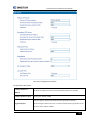
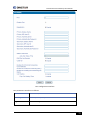
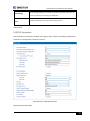
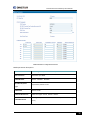
1
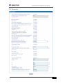
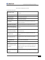
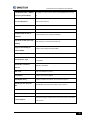
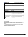
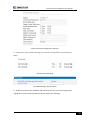
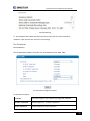
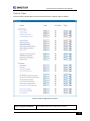
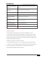
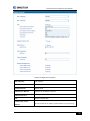
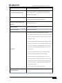
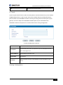
DINSTAR FXS VoIP Gateway User Manual V1.0 Dinstar Technologies Co., Ltd. Address: Floor 6 Guoxing Building Changxing Road Nanshan District Shenzhen China 518052 Telephone: 86-755-26456664 Fax: Email: Website: 86-755-26456659 [email protected], [email protected] www.dinstar.com Revision Records File Name The FXS VoIP Gateway User Manual Date 2014/10/20 Revised by Technical Support Department Table of Contents Table of Contents .....................................................................................................................3 Chapter1: Introduction ...............................................................................................................1 Welcome.............................................................................................................................1 About this manual ..............................................................................................................1 Intended audience..............................................................................................................1 Chapter2: Know your Gateway ..................................................................................................2 Overview.............................................................................................................................2 Equipment Appearance ......................................................................................................2 Ports and Connectors .........................................................................................................3 Network Applications .........................................................................................................4 Functions and Features ......................................................................................................4 Protocol standard supported .....................................................................................4 Voice and Fax parameters ..........................................................................................5 Supplementary service ...............................................................................................5 Chapter3: Basic Operations ........................................................................................................6 Phone Call ...........................................................................................................................6 Direct IP Calls ......................................................................................................................6 Call Hold..............................................................................................................................7 Call Waiting.........................................................................................................................7 Call Transfer ........................................................................................................................7 Blind Transfer .............................................................................................................7 Attended Transfer ......................................................................................................8 3-way Conference...............................................................................................................8 Call Features .......................................................................................................................8 Sending and Receiving Fax ...............................................................................................10 T. 38 and Pass-Through ............................................................................................10 Local IVR Operation ..........................................................................................................10 Inquire IP address .....................................................................................................10 Factory Reset ............................................................................................................10 Configure LAN Port’s IP Address...............................................................................10 Chapter4: Web Configuration ..................................................................................................11 Getting start .....................................................................................................................11 Network connection .........................................................................................................12 Get Web access ................................................................................................................13 Navigation Tree ................................................................................................................13 State and Statistics ...........................................................................................................14 System Information ..................................................................................................14 Registration Information .......................................................................................17 TCP/UDP Statistics .................................................................................................17 RTP Session Statistics ............................................................................................18 Quick Setup Wizard ..........................................................................................................18 Network Configuration .....................................................................................................18 Local Network .........................................................................................................18 VLAN Parameter .....................................................................................................21 Qos ...........................................................................................................................23 LAN Qos ...................................................................................................................23 DHCP Server (Routing mode)...............................................................................24 DMZ Host (Routing mode) ....................................................................................24 Forward Rule (Routing mode) ..............................................................................25 Static Route Table ..................................................................................................26 Firewall.....................................................................................................................27 ARP ...........................................................................................................................27 SIP Server ..........................................................................................................................28 Port Configuration ............................................................................................................30 Advanced ..........................................................................................................................33 FXS/FXO Parameters .............................................................................................33 Media Parameter ....................................................................................................35 SIP Parameter .........................................................................................................38 Fax Parameter ........................................................................................................43 Digit Map .................................................................................................................44 Feature Codes .........................................................................................................47 System Parameter ..................................................................................................49 Action URL ...............................................................................................................51 Call & Routing ...................................................................................................................52 Wildcard Group ........................................................................................................52 Port Group ...............................................................................................................52 IP Trunk ...................................................................................................................55 Routing Configuration............................................................................................55 IP-Tel Routing .........................................................................................................56 Tel-IP/Tel Routing ..................................................................................................57 IP – IP Routing .......................................................................................................58 Manipulation Configuration .............................................................................................59 IP-Tel Callee ............................................................................................................59 Tel-IP/Tel Caller......................................................................................................61 Tel-IP/Tel Callee .....................................................................................................62 Routing rule examples ......................................................................................................62 Route any calls from any IP to specific port ......................................................62 Route any calls from any IP to specified port group ........................................63 Route any calls from any port to specific SIP IP trunk .....................................64 Maintenance.....................................................................................................................65 TR069.......................................................................................................................65 SNMP ........................................................................................................................66 Syslog .......................................................................................................................68 Provision ..................................................................................................................70 Cloud server ............................................................................................................71 User Manage ............................................................................................................71 Security .............................................................................................................................72 WEB ACL ...................................................................................................................72 Telnet ACL .................................................................................................................72 Passwords .................................................................................................................72 Tools .................................................................................................................................73 Firmware upload ......................................................................................................73 Data Backup..............................................................................................................75 Data Restore .............................................................................................................75 Ping Test ...................................................................................................................76 Tracert Test...............................................................................................................76 Outward Test ............................................................................................................78 Network Capture ......................................................................................................78 Factory Reset ............................................................................................................82 Device Restart...........................................................................................................82 Charpter5. Glossary ..................................................................................................................83 Dinstar FXS Voice Gateway User Manual Chapter1: Introduction Welcome Thanks for choosing DINSTAR FXS VoIP Gateway (hereafter named “GATEWAY”, “DEVICE”)! We hope you will make optimum use of this flexible, rich-features multi-ports VoIP to FXS gateway. Please read this document carefully before install your gateway. About this manual This manual provider information about and introduction of installing, configuring and using the gateway. For interoperability with different IPPBX/Softswitch platform, you may refer to configure guide with different system. This manual is available in different configurations. It is written with reference to the default configuration of the DAG1000-4S FXS VoIP Gateway. Intended audience This Manual is aimed primarily at Network and system engineers, who will install, configure and maintain the gateway. System engineers are persons who customize the system configuration to meet the requirements of users. Parts of document containing description of telephony features are aimed at users, who are the persons who will actually use the gateway. 1 Dinstar FXS Voice Gateway User Manual Chapter2: Know your Gateway Overview DINSTAR FXS VoIP gateway is the gateway that provide voice service based on IP network. It’s a cost-effective and flexible solution for SOHO (Small Office-Home office), remote office and branch enterprise, as well as Medium sized enterprise. The GATEWAY connects to analog telephone, fax and traditional analog PBX with standard voice interfaces and provided high quality voice service. The GATEWAY adopted standard SIP protocol and compatible with leading IP PBX, softswitch and SIP-based platform. The FXS analog gateway available in the following configurations: Sr. No. Model 1 DAG1000-4S Voice Channels 4 FXS Ports 4 Physical Port Labels 0-3 For a complete list of Hardware and Software features, refer to “product specifications”. This manual mainly to the DAG1000-4S as examples, introduce the function of devices and parameter configuration. Equipment Appearance DAG1000-4S 2 Dinstar FXS Voice Gateway User Manual Ports and Connectors Port Name Connector DC12V 1.0A DC Jack 0-3 RJ11 Ethernet RJ45 RST Description to connect 12VDC,1A Power adapter FXS ports to connect standard analog phone or FAX machine or a PBX LAN to connect with local PC, WAN port to connect the IP network over a DSL modem or Router or a LAN switch Keep press 10 seconds to reset to factory default settings 3 Dinstar FXS Voice Gateway User Manual Network Applications Network Applications Functions and Features Protocol standard supported • SIP V2.0 (RFC 3261,3262,3264) • IMS/3GPP • SDP (RFC 2327) • REFER (RFC 3515) • RTP/RTCP (RFC 1889,1890) • STUN (RFC 3489) • ARP/RARP (RFC 826/903) • SNTP (RFC 2030) • DHCP/PPPoE • TFTP/HTTP 4 Dinstar FXS Voice Gateway User Manual • VLAN 802.1P/802.1Q • V.152 Voice and Fax parameters • G.711A/U, G.723, G.729,G.726 • Comfort Noise Generation(CNG) • Voice Activity Detection(VAD) • Automatic Gain Control(AGC) • Echo Cancellation(G.168) • Adaptive (Dynamic) Jitter Buffer • Hook Flash • Programmable Gain Control • T.38/Pass-through,up to 14.4kbps • Modem/POS • DTMF mode: Signal/RFC2833/INBAND Supplementary service • Call Waiting • Blind • Attend Transfer • Call Pickup • Call Forward on Busy • Call Forward on No Reply • Unconditional Call Forward • Hotline • Call Hold • DND • 3-way conference • Voicemail Transfer 5 Dinstar FXS Voice Gateway User Manual Chapter3: Basic Operations Phone Call Dial mobile phone or Extension Number Dial the number directly and wait for 3 seconds (Default “No dial timeout”); Dial the number directly and press #. Direct IP Calls THE GATEWAY with FXS port allow two parties directly call through IP address. The user need only a simulation with the FXS port unit equipment linked together and set up calls not registered. Elements necessary to completing a direct IP call: Both the GATEWAY and other VoIP Device, have public IP addresses; Both the GATEWAY and other VoIP Device are on the same LAN using private IP addresses; Both the GATEWAY and other VoIP Device can be connected through a router using public or private IP addresses (with necessary port forwarding or DMZ). Operation Process: Pick up the analog phone then dial “*47” Enter the target IP address. 【Note】: No dial tone will be played between step 1 and step 2 Examples: If the target IP address is 192.168.0.160, the dialing convention is *47, then 192*168*0*160. Followed by pressing the “#” key or wait 3 seconds. Complete signaling interactive soon after, he was called the unit can be heard ringing. 【Note】:You cannot make direct IP calls between FXS0 to FXS1 since they are using same IP. It only supports the default destination port 5060. 6 Dinstar FXS Voice Gateway User Manual Call Hold Place a call on hold by pressing the “flash” button on the analog phone (if the phone has that button).Press the “flash” button again to release the previously held Caller and resume conversation. If no “flash” button is available, use “hook flash” (toggle on-off hook quickly). You may drop a call using hook flash. Call Waiting Call waiting tone (3 short beeps) indicates an incoming call, if the call waiting feature is enabled. Toggle between incoming call and current call by pressing the “flash” button. First call is placed on hold. Press the “flash” button to toggle between two active calls. Call Transfer Blind Transfer Blind transfer used to transfer call to the third party without inform caller. Assume that call Caller A and B are in conversation. A wants to Blind Transfer B to C: Caller A presses FLASH on the analog phone to hear the dial tone; Caller A dials *87 then dials caller C’s number, and then # (or wait for 4 seconds); Caller A will hear the confirm tone. Then, A can hang up. Note: “Call features enable” must be set to “Yes” in web configuration page. Caller A can place a call on hold and wait for one of three situations: A quick confirmation tone (similar to call waiting tone) followed by a dial-tone. This indicates the transfer is successful. At this point, Caller A can either hand up or make another call. A quick busy tone followed by a restored call (on supported platforms only). This means the transferee has received a 4xx response for the INVITE and we will try to recover the call. The busy tone is just to indicate to the transferor that the transfer has failed. Continuous busy tone. The phone has timed out. 7 Dinstar FXS Voice Gateway User Manual Attended Transfer Attended transfer allows users to confirm the third party response and decide whether to answer the calls and then transfer this call to the third party. Assume that Caller A and B are in conversation. Caller A wants to Attend Transfer B to C: Caller A presses FLASH on the analog phone for dial tone; Dial Caller C’s number followed by # (or wait for 3 seconds); If Caller C answers the call, Caller A and Caller C are in conversation. Then A can hang up to complete transfer; If Caller C does not answer the call, Caller A can press “flash” to resume call with Caller B. 3-way Conference 3-way conference: Caller A call B,B pick up into call states; Caller A hook flash, A and B into keep states, then C call A, A through to the phone. A hook flash, then A、B、C into keep states, at this time if A press 1 key, then A and B continue to call; if A press 2 key, then A and B continue to call; if A press 3 key, then A,B,C three parties go to call. Call Features The GATEWAY (FXS) support all traditional and senior phone function. 8 Dinstar FXS Voice Gateway User Manual Table 2.5-1 Feature Codec Feature Codec Operation Instructions *158# View the LAN port IP address *159# View the WAN port IP address *114# Inquire port account *115# Inquiry PortGroup Number *150* Set the way of obtain IP address *157* Set network method *152* Set IP address *153* Set Subnet mask *156* Set default gateway IP address *193# Obtain IP address through DHCP again *160*1# Open WAN port to access web *165*000000# Reset Basic Configuration *166*000000# Reset Factory Configuration *111# Restart device *# Call hold *47* IP address call *51# Enable call waiting *50# Disable call waiting *87* Blind transfer *72* Enable Unconditional Call Forward *73# Disable Unconditional Call Forward *90* Enable Busy Call Forward *91# Disable Busy Call Forward *92* Enable No Answer Call Forward 9 Dinstar FXS Voice Gateway User Manual *93# Disable No Answer Call Forward *78# Enable DND *79# Disable DND *200# Access Voice mail Flash/Hook Switch between incoming calls, If not in session, flash/hook will switch a new channel for new call. Sending and Receiving Fax THE GATEWAY(FXS)support four fax modes: Pass-Through(T.30) Pass-Through(VBD) T.38 Adaptive T. 38 and Pass-Through T.38 is the preferred method because it is more reliable and works well in most network conditions. If the service provider supports T.38, please use this method by selecting T.38 as fax mode (default). If the service provider does not support T.38, pass-through mode may be used. If you have problems with sending or receiving Fax, toggle the Fax Tone Detection Mode setting. Local IVR Operation Inquire IP address Analog phone connected with FXS ports of device, then pick up, after dial tone, dialing *158# to inquire LAN port IP address and dialing *159# to inquire WAN port IP address. Factory Reset After picking up, dial *166*000000#, then onhook and restart after “Setting successful”. Configure LAN Port’s IP Address Before configuration, please ensure: 10 Dinstar FXS Voice Gateway User Manual The device is power on; Device is connecting to network; Telephone is connected to FXS port of device. Configure dynamic IP address by DHCP: Offhook; Dial “*150*2#”; Onhook; If the equipment hint success, after 10 seconds, and restart the equipment. (Power-off then power-on) Configure Static IP address: Offhook; Dial “*150*1#”; Onhook; Then configure IP and mask as follow: • Configure IP address: Offhook; input “*152*172*16*0*100# ”; onhook • Configure subnet mask Offhook; input “*153*255*255*0*0# ”; onhook • Configure gateway IP address Offhook; input “*156*172*16*0*1# ”; onhook. • Query the IP address of device: Offhook, input“*158#” If the THE GATEWAY serial uses PPPoE method to get IP address,it need to configure by web browser. 【Note】:The telephone will play voice prompt “Setting successfully” if the step is correct Chapter4: Web Configuration Getting start Device is connecting to network properly, refer to chapter 3 “basic Operation”. Offhook and dial*158# to inquire device IP address. 11 Dinstar FXS Voice Gateway User Manual Network connection Device LAN port default IP address is 192.168.11.1, WAN port default obtain IP address by DHCP. Advice to modify the IP address of the local computer equipment and ensure that are on the same IP segment, with Windows 7 as an example, the local computer IP address change for 192.168.11.10: Modify IP address Check connection between computer and device, click “Start”-> “run”-> input “cmd”, run ping 192.168.11.10 –t order to check the connectivity between them. Connect to private network (behind NAT) 12 Dinstar FXS Voice Gateway User Manual Get Web access Open web browser, then input IP address of device, Press“Enter”, it pop up logging on identity authentication interface. The GATEWAY Login Interface Default username and password: admin/admin, click “OK” to entry into web interface. Navigation Tree The GATEWAY series voice gateway web configuration interface mainly includes navigation tree and the right configuration interface. Choose navigation tree in order to entry into the configuration interface. 13 Dinstar FXS Voice Gateway User Manual When device is in bridge mode, navigation tree won’t display "routing configuration" items and the following "DHCP service", "DMZ host", "forward rules" and "static routing" and "ARP" etc. State and Statistics System Information You can view the information of Device ID, MAC address, IP addresses, version information and Sever registration status System information interface shows the run information as following figure as below: 14 Dinstar FXS Voice Gateway User Manual Figure 4.3-1 System Information System information as follow: System Information Description Device ID An unique ID of each device, this ID is use for cloud server authentication and warrantee purpose MAC address WAN port hardware address. The device ID in HEX format. Display network mode, include bridge and router. Bridge mode, the Ethernet port will work Network Mode as a small lanswitch. Router Mode, NAT feature will be enabled in this mode. WAN port IP only display while the gateway set to Router Mode. Network Display WAN and LAN port IP address, subnet mask and the way of obtain IP address. 15 Dinstar FXS Voice Gateway User Manual Shows WAN IP address of the gateway , DHCP mode: all the field values for the Static IP mode are not used (even though they are still saved in the Flash memory.) The GATEWAY acquires its IP address from the first DHCP server it discovers from the LAN it is connected. WAN IP Address Using the PPPoE feature: set the PPPoE account settings. The gateway will establish a PPPoE session if any of the PPPoE fields is set. Static IP mode: configure the IP address, Subnet Mask, Default Router IP address, DNS Server 1 (primary), DNS Server 2 (secondary) fields. These fields are set to zero by default. LAN IP address Shows LAN IP address of the gateway. if network Mode is bridge, LAN port won’t display. DNS Server Display DNS server IP address and default gateway information System Uptime Time elapsed from device power on to now. Succeed: the gateway is sync to NTP server successful NTP Status Failed: failed to sync to NTP server then you should check network connection/NTP server NTP time Current time of the gateway Network Traffic Statics Total bytes of message received and sent by network port. Usage of Flash Detailed usage of Flash memory Usage of RAM in Linux Detailed RAM usage of Linux core Usage of RAM in AOS Detailed RAM usage of AOS Current Software Software version that running on the gateway. The version number consist of Model Name, Version Version number, Built date Backup Software Version There are two zone to storage software version. Backup software is for roll back purpose while current software fail. The backup software version consist of Model Name, Version number, built date U-boot U-boot version Kennel version Linux Kennel version FS Version File system version 16 Dinstar FXS Voice Gateway User Manual Hint Language Hit language of the gateway Registration Information Port and Port group registration information Primary/Secondary User status: Registered: the port is register to SIP server successfully Unregistered: failed to register to SIP server TCP/UDP Statistics TCP/UDP Statistics Information The picture show above is TCP sending and receiving, UDP sending and receiving packets of statistical information since the device launched. 17 Dinstar FXS Voice Gateway User Manual RTP Session Statistics Figure 4.3-4 RTP Session Statistics The picture show above is real-time RTP conversation flow data information, includes: Port, voice codec, packet period, local port, peer IP, peer port, sent packets, receive packets, lost packets, jitter and duration. Quick Setup Wizard Quick configuration guide will guide users to configure the device step by step. Users only need to configure network, SIP server and sip port in quick setup wizard. Basically, after these three steps, users are able to make voice call through device. Network Configuration Local Network The GATEWAY has two kinds of work mode: route and bridge. When the GATEWAY is set rout mode, the GATEWAY will work as small router and NAT function has enabled. In this situation, WAN port is normally connect to uplink router/switch or ADSL MODEM, LAN port used to connect local computer or other network device(such as Ethernet switches, Hubs etc.); When the GATEWAY is set bridge mode, WAN and LAN port are the same. The GATEWAY just work as two ports or four ports Ethernet switch. When it set to bridge mode, only need to configure WAN port IP address and DNS. If set to route mode, default LAN port IP will display and it can be change by users. Network configure interface as below: 18 Dinstar FXS Voice Gateway User Manual Figure 4.5-1Route Mode 19 Dinstar FXS Voice Gateway User Manual Bridge Mode “Link Speed & Duplex” used to select Ethernet port work mode, include 5 kinds of choice, “Auto Detect”、“10Mbps half-duplex”、“10Mbps full-duplex”,“100Mbpshalfduplex”,“100Mbps full-duplex”, default is “Auto Detect”. When select “Obtain IP address automatically”, the GATEWAY will obtain IP address by DHCP. When select “Use the following IP address”, that configure the GATEWAY to fixed IP address mode. When select “PPPoE”, please fill in account and password offered by ISP in internet account and password. 【Notes】: 20 Dinstar FXS Voice Gateway User Manual If select DHCP to obtain IP address, please ensure DHCP server in network and work normally. Under route mode, please configure LAN port and WAN port in different segment, otherwise the GATEWAY can’t work normally. Under route mode, login the GATEWAY configuration interface only used LAN port. After configuration, restart device configuration validation. VLAN Parameter Generally, Internet provides only Best Effort Service. Since Ethernet is the most spread LAN access technology, importance of providing it a quality of service mechanism ought not to be neglected. Ethernet technology also used as WAN technology, not only as LAN technology. Due to rapidly increasing use Internet through Public Switched Telecommunication Network (PSTN), Telephone Companies are forced to implement IP-based networks as their PSTN backbones. A network like this without any Quality of Service mechanisms would be disastrous. Just imagine yourself trying to get an emergency call through while others just surf the Internet. 802.1Q The IEEE 802.1Q standard defines architecture for Virtual Bridged LANs, the services provided in Virtual Bridged LANs and the protocols and algorithms involved in the provision of those services. No Quality of Service mechanisms are defined in this standard, but an important requirement for providing QoS is included in this standard, e.g. abitity to regenerate user priority of received frames using priority information contained in the frame and the User Priority Regeneration Table for the reception Port. 802.1p IEEE 802.1p standard, Traffic class expediting and dynamic multicast filtering. It describes important methods for providing QoS at MAC level. IEEE 802.1p is in fact quite good. Lower priority level packets are not sent, if there is packets in queued in higher level queues. IEEE 802.1p describes no admission control protocols. It would be possible to give Network Control priority to all packets and the network would be easily congested. 21 Dinstar FXS Voice Gateway User Manual There are three VLAN: data VLAN, voice LAN and management VLAN. VLAN configuration interface as below: Figure 4.5-3 VLAN parameter configuration Table 4.5-1VLAN parameter configuration Fill out an ID to describe a data VLAN group, ID 0 used Data 802.1Q VLAN ID(0-4095) to management VLAN, can’t use to service configure. Data VLAN 802.1 protocol to control network traffic priority, Data 802.1p Priority(0-7) Priority from 0-7. Fill out an ID to describe a voice VLAN group, ID 0 used Voice 802.1Q VLAN ID(0-4095) to management VLAN, can’t used to service configure. Voice VALN 802.1 protocol to control network traffic priority, Voice 802.1p Priority(0-7) Priority from 0-7. IP address Can use dynamic or static IP address 22 Dinstar FXS Voice Gateway User Manual Voice VLAN DNS Server Can use dynamic or static DNS server address Management 802.1Q VLAN ID(0- Fill out an ID to describe a data VLAN group, ID 0 used 4095) to management VLAN, can’t used to service configure. Management Management 802.1p Priority 802.1 protocol to control network traffic priority, VLAN (0-7) Priority from 0-7. IP address Can use dynamic or static IP address Management VLAN DNS server Can use dynamic or static DNS server address 【Note】:Restart the device to take configuration effect. Qos DSCP code point is used for diffserv setting. It utilizes the first 6 bits of IP ToS. The default values are EF(184), AF1(1), AF2(2), AF3(3), AF4(4), BE(0). You can use different DSCPs for voice or data based on the network provider. LAN Qos Use LAN Qos to control the Priority of LAN port or WAN port,and Incoming Rate Limit and Outgoing Rate Limit. 23 Dinstar FXS Voice Gateway User Manual DHCP Server (Routing mode) Under route mode, the GATEWAY network part as a small router to configure DHCP service, that the GATEWAY as a DHCP server in network. Start and end address of address pool determine the range of IP address automatically assigned to other devices; IP Expire Time means use time of assigned IP address. More than the lease time, if the IP address is not used by network equipment, IP address will be recovered; Subnet mask, gateway, DNS and other information configured by DHCP protocol. Configuration interface as below: Configuration Interface 【Note】: When configure start and end IP address, subnet mask and gateway, please set the same segment with LAN port. Otherwise, device will not work normally. After configuration, restart device configuration validation. DMZ Host (Routing mode) DMZ (Demilitarized Zone) connect web, e-mail etc. server allowed external to access to this area. Make the internal network located the back of the zone of confidence and not allow any access, separation of inside and outside the network, protect user information. DMZ can be understood that a special areas of the network and different from the external network or intranet. Public 24 Dinstar FXS Voice Gateway User Manual server that does not contain confidential information usually placed in DMZ, such as web, Mail, FTP etc. Accuser from intranet can visit the service of DMZ, but can’t come into contact with confidential or private information stored in the network. Even if DMZ server is damaged, it will not be confidential information in the internal network. DMZ Configuration Interface 【Note】: After configuration, restart device configuration validation. Forward Rule (Routing mode) In some cases, LAN network equipment need to provide some communication in WAN network (such as port for 21 FTP service), this time can be configured forwarding rules for the network equipment. Service ports namely the need to provide service network mouth WAN ports, IP address that LAN network provide services to the mouth of the network equipment IP address, the protocol is TCP or UDP. The different between forward rule and DMZ host is that DMZ Host offers continuous multiple Port (0-1024) and all the foreign communication agreement; while the forward rule offers a Single or a few port foreign communication on some protocol. When the conflicts exist between forward rule and DMZ host, the configuration of forwarding rules is preferred. Forward rule configuration interface as follows: 25 Dinstar FXS Voice Gateway User Manual Forward rule configuration interface Static Route Table Static Route Table is IP communication direction in network, generally do not need to configure static route. When there are many segments in LAN network and need to complete some specific application among these segments, the static route need to be configured. Static Route configuration interface as follows: Static route configuration interface 26 Dinstar FXS Voice Gateway User Manual Firewall Firewall refuse messages that the MAC or domain send.IP Filter stop the range of ip send messages pass through the route. ARP ARP is address resolution protocol. After configuring ARP, users can get physical address through device IP address. Under TCP/IP network environment, each host is assigned a 32-bit IP address. But the message transmission needs to know the purpose the physical address of the party. ARP is a tool that converts IP address into MAC address. ARP configuration interface as follows: 27 Dinstar FXS Voice Gateway User Manual Figure 4.5-9 ARP Parameters SIP Server SIP server introduction: 1)SIP server is the main component of VoIP network and responsible for establishing all the SIP phone calls. SIP server also called SIP proxy server or registered server. IPPBX and the soft-switch can act as SIP server role. 2)Usually, SIP server does not participate in the media process. In SIP network, the media always using end-to-end to hand the consultation. In some particular situation or business processing, such as “Music On Hold”, SIP server will actively participate in the media negotiation. Simple SIP server is responsible only for establishment, maintenance and cleaning conversation, don't interfere in call. While relatively complex SIP server also called SIP PBX. It not only provides the basic cal l, and basic conversational support, also offer plenty of business, such as: Presence, Find-me, Music On Hold. 3)SIP server based on Linux platform, such as: OpenSER、sipXecx,VoS,Mera etc. 4)SIP server based on windows platform, such as :mini SipServer、Brekeke,VoIPswitch etc. 5)Carrier grade soft-switch platform, such as Cisco, Huawei, ZTE etc. SIP server configuration interface as follows: 28 Dinstar FXS Voice Gateway User Manual SIP Server Configuration Interface SIP parameter description: Primary SIP Server Address Primary SIP Server port SIP Server IP address or Domain name provided by VoIP service provider. Service port, default is 5060 protects registrar against excessively frequent registration refreshes Register Expires while limiting the state. Every once in a while send request for registration to the terminal server, default is 1800s. 29 Dinstar FXS Voice Gateway User Manual Heartbeat Heartbeat message detect the connection status between device and SIP server. Secondary SIP Server Backup SIP Server’s IP address or Domain name provided by VoIP service address provider. Secondary SIP Server port Service port, default is 5060 protects registrar against excessively frequent registration refreshes Register Expires while limiting the state. Every once in a while send request for registration to the terminal server, default is 1800s. Secondary SIP heartbeat Heartbeat message detect the connection status between device and SIP server. Outbound Proxy Address Outbound proxy IP address or Domain name provided by VoIP service provider. Outbound Proxy Port Default outbound proxy SIP service port is 5060. Retry Interval when Registration failed The retry interval time after the registration failed last time Registration times per second Limit the gateway to send REGISTER messages per second SIP Transport Type The SIP transport type, can be UDP, TCP, Auto; default to UDP Use Random Port Random SIP service ports for gateway SIP Local Port Default SIP local service port is 5060. Port Configuration Port parameters include: Send gain, receive gain, primary display name etc. 30 Dinstar FXS Voice Gateway User Manual Port configuration interface Port parameters introduce as follows: Port Port number, Disable port Disable port temporally Registration Whether to register the SIP server 31 Dinstar FXS Voice Gateway User Manual It is use to control the volume of conversation, Adjust "TX gain" will Tx Gain affect the end users voice size, the default value is 0. Its value range from-10 – 10 dB It is use to control the volume of conversation, Adjust "RX gain" will Rx Gain affect the end users voice size, the default value is 0. Its value range from -10 – 10 dB Primary /Secondary Primary /Secondary SIP account description, Its purpose is so you can SIP Display Name identify the SIP account with a meaningful name Primary /Secondary SIPUser ID User account information, provided by VoIP service provider (ITSP). Usually in the form of digit similar to phone number or actually a phone number. Primary/Secondary SIP service subscriber’s Authenticate ID used for authentication. Can be SIP Authenticate ID identical to or different from SIP User ID. Primary/Secondary Authenticate SIP password which registers to soft switch/SIP server password Offhook Auto-dial Pre-assign an extension or phone number so that automatically dial a number as soon as you pick up the phone set Auto-dial Delay Delay 0-3 seconds to automatically dial a number, 0 means dial number Time immediately DND Do not disturb, the phone set won’t receive any calls in case it enabled Caller ID Enable or disable caller ID for corresponding port Number for CFU call forward unconditional, all incoming calls willforward to pre-assigned number automatically Number for CFB Call forward on busy, if the line is busy, the call will forward to preassigned number automatically Number for CFNRy Call forward no reply, if the line is not answer the call, the call will forward to pre-assigned number automatically 32 Dinstar FXS Voice Gateway User Manual Call Waiting If call waiting enabled, it will send a special tone if another caller tries to reach you when you are using your telephone Play Call Waiting Tone Enable call waiting tone, caller will hear special tone. Advanced FXS/FXO Parameters FXS characteristic parameters include: Call progress Tone, Timeout for Dialing, Send Polarity Reversal etc. Configuration interface as follow: FXS Parameters Configuration Interface FXS parameters description: 33 Dinstar FXS Voice Gateway User Manual With the help of dialing timeout, you can limit the time while users typing the digits from an extension. If the timeout expire while the Timeout for dialing user is typing in the extension then the GATEWAY will consider the extension as complete and it will try to send to SIP server. Default value is 4 seconds Timeout for This timer set how long the caller party waiting when makes outgoing answer(Outgoing call) call on extension. Timeout for answer(Incoming call) No RTP Detected This timer set how long the phone sets ringing when get incoming call Detect when there’s no RTP packet receive Period without RTP Packet Call Process Tone The time interval of No RTP packet Hear the dial tone when pick up the phone. Choose the national standards from the drop-down box. Default is the United States. Auto Gain Control Enable automatic gain control Send Polarity Reversal Enable polarity reversal to billing. A protruding button where putting the receiver boards, called Flash. Always press is hang up, pick up the receiver, the fork lift machine from reed called, by hand clap called "Hook flash". Hook flash is a process that put the flash fast by pressing and let go.In essence is to Detect Hook flash cut off the dc access about 80 to 200 ms. Then switches don't think it's hang on, but keep the call, taking some other operating. The typical application of hook flash is the telephone switchboard. When need to transfer the call to other extension, then telephone hook flash to transfer the call. CID Type There are DTMF and FSK, General for the default. Message Type The call display types SDMF and MDMF, General for the default 34 Dinstar FXS Voice Gateway User Manual The call display format send to analog phone, can be “Display Name Message Format and CID”, “CID only”, or “Display Name only”; default to “Display Name and CID” Send CID before Ringing After enable this configuration, The THE GATEWAY send caller to phone set before ringing, otherwise the caller ID will display after ringing. Delay of sending CID Definite delay timer of caller ID while it set to send caller ID after after Ringing ringing. Its Default value 500ms CFNRy Timeout Timeout for call forward No Answer SLIC Setting Set the unit impedance Long Line Support Enable Long Analog extension line Media Parameter Media parameter mainly include: RTP start port, DTMF parameter, Preferred Vocoder. Configuration Interface as follow: 35 Dinstar FXS Voice Gateway User Manual Media Parameter Configuration Interface Media parameter description: Use Random Port Enable the gateway to use random RTP port RTP Start Port Default RTP port 8000 DTMF Method SINGAL、INBAND、RFC2833 RFC2833 Payload Type Payloadvalue, default is 101 DTMF Gain Default is 0 DB DTMF Send Interval DTMF send signal interval, default is 200ms. Send Flash Event Enable gateway to send flash event to remotely instead of handling it locally 36 Dinstar FXS Voice Gateway User Manual Coder Name THE GATEWAY supports G729、G711U、G711A、G723. while it make outgoing call, G.729 will used as figure 4.8.2 displayed Payload Type Each kind of coding has a unique type load value, refer toRFC3551 Packetization Time Voice package time Rate Voice data flow rate, system default Default is disable, if enable, according to the current noise environment dynamically adjust mute inhibit threshold,thus in the user Slience Suppression in silent state stop transmission background noise bag and save about VoIP bandwidth.In the low bandwidth environment, can reduce the network congestion, greatly improving VoIP call effect. 37 Dinstar FXS Voice Gateway User Manual SIP Parameter 38 Dinstar FXS Voice Gateway User Manual SIP Parameter Configuration Interface SIP parameter description: SUBSCRIBE for MWI Voicemail message indicator, it is to be realized in the way of NOTIFY MWI Subscription Expires MWI subscription expires time, default to 3600 Voicemail User ID Access code to voicemail box RFC3407 Support Enable support of RFC3407 IP-to-IP Call Enable this function, users may use the * business call IP address on the phone. URI Includes user=phone SIP carries the information, the system defaults not open. INVITE with”P-Preferred- Support RFC3325, add “P-Preferred-Identity” Header in INVITE Identity” Header (RFC3325) message Only Accept Call from ACL Default is no, it indicates the GATEWAY accept incoming call (SIP server or IP Trunk) from SIP server only Anonymous Call Enable anonymous call, “anonymous” will include in SIP message Reject Anonymous Call Enable this function, reject all anonymous call. Disable by default # as ending Dial Key Dial-up, use # as a end descriptor. # Escape Escape # key Its function is to require the receiving party contact with the Value of “Refer To“ refers third party through the use of supplied in the request in the to ”Contact” address information. “Refer to” field of SIP message fill in “contact header”. Third Party Do Not Send 18x Send 18x response when acting as third party in a attended Response transfer 39 Dinstar FXS Voice Gateway User Manual Send BYE when Recv REFER Send BYE to release session after receiving REFER when acting Response (unattended) as Send New REGISTER when Update the value of expires header and re-send REGISTER when Recv 423 Response receive 423 response Implicit Subscribe Accept implicit subscription CSeq Start with 1 Value of CSeq start with 1 Forbid Invilad m=line in reINVITE Forbid invilad m=line in SDP of re-INVITE RTP Mode in SDP when Call Holding Use sendonly or inactive to hold the call Support Call Waiting of Huawei IPPBX Accept Orphan 200 OK Domain Query Type Support call waiting of Huawei IPPBX Support different to-tag 200 OK in a INVITE session There are two modes option: A QUERY and SRV QUERY. Default is A QUERY. Domain Re-resolution Interval Default 0: forbidden DNS cache Cache the DNS query result Early Media Support receive Early Media PRACK(RFC3262) Support reliable transmission of provisional response PRACK Only for 18x with SDP Send PRACK only when there’s SDP in 18x response Early Answer Support contain SDP in 18x Session Timer (RFC4028) Enable session timer, default to no Session-Expires The Session-Expires header field conveys the session interval for a SIP session. 40 Dinstar FXS Voice Gateway User Manual Min-SE Min-SE header field indicates the minimum value for the session interval. T1 T1 timer of SIP protocol, default is 500ms T2 T2 timer of SIP protocol, default is 400ms T4 T4 timer of SIP protocol, default is 500ms Max Timeout The max timeout of sending or receiving, default is 32s Heartbeat Interval Default is 10s. Heartbeat Timeout Default to 16s Username of OPTION(Heartbeat) for “SIP Server” The user ID part of OPTION SIP message in the heartbeat request for SIP server Username of OPTION(Heartbeat) for “IP TRUNK” The user ID part of OPTION SIP message in the heartbeat request for IP trunk Voice mail instructions: Here the GATEWAY work with Elastix as the example, introduces how voicemail work in the GATEWAY. 1)the GATEWAY register to Elastix server. Corresponding extension number enable voice mail function in Elastix and set password. As below: 41 Dinstar FXS Voice Gateway User Manual Elastix Voicemail Configuration Interface 2)check feature code in Elastix and change it as necessary. Its default feature codes setting as below: Elastix Voicemail Setting VoiceMail Setting In SIP Parameter 3)Enable voice mail in the GATEWAY and Elastix will ask you to leave a message after ringing 15 seconds, then Elastix will record and display your message. 42 Dinstar FXS Voice Gateway User Manual Voicemail Setting 4)the GATEWAY dial *200#, then dial voicemail account and then ask password for Validation. After that the user will hear voice message. Fax Parameter Fax introduction: The fax parameter includes: fax mode, Fax sound detection party, ECM, Rate. Fax Parameter Configure Interface Fax parameter description: Fax Mode Fax mode support T.38, T.30(Pass-through),VBD, Adaptive. “a=X-fax” expansion Enable support of “a=X-fax” expansion “a=fax” expansion Enable support of “a=fax” expansion 43 Dinstar FXS Voice Gateway User Manual “a=X-modem” expansion “a=modem” expansion ECM Enable support of “a=X-modem” expansion Enable support of “a=modem” expansion If the ECM receiver is enabled, the sending fax machine will automatically after correcting the error resend the fax Rate 2400bps-14400bps Tone Detection by Fax sound detection mode: Local,Peer Switch into Fax Mode When Detected CNG or Switch into Fax Mode When Detected CNG or CED CED Digit Map Digit Map Gateway is collect digits dialed by user, if received a number to be immediately report, the efficiency is too low and a large number of take up network resources. A reasonable method is concentration sending a message after receiving all number. How to judge the gateway 44 Dinstar FXS Voice Gateway User Manual receiving all number is the difficulties of this method. The solution is the call agent loading a “Digit Map” to gateway. Digit Map includes a series figure characters, when the dial-up sequence and one received a character string matching, it means the number has received neat. Digital string contains characters allowed:data0~9, letterA~D,“#”,“*”, letter T, letter x and “.”. "|" parts of each string is a choice of dial-up solutions; “[]”means choose anyone;“*”means one reports; letter T means detected timer overtime; x means any data; “.”means multiple characters can be behind,include 0; “#”means report immediately. Digit Map Syntax: 1. Supported objects Digit: A digit from "0" to "9". Timer: The symbol "T" matching a timer expiry. DTMF: A digit, a timer, or one of the symbols "A", "B", "C", "D", "#", or "*". 2. Range [] One or more DTMF symbols enclosed between square brackets ("[" and "]"), but only one can be selected. 3. Range () One or more expressions enclosed between round brackets ("(" and ")"), but only one can be selected. 4. Separator |: Separated expressions or DTMF symbols. 5. Subrange -: Two digits separated by hyphen ("-") which matches any digit between and including the two. The subrange construct can only be used inside a range construct, i.e., between "[" and "]". 6. Wildcard x: matches any digit ("0" to "9"). 7. Modifiers 45 Dinstar FXS Voice Gateway User Manual .: Match 0 or more times. 8. Modifiers +: Match 1 or more times. 9. Modifiers ?: Match 0 or 1 times. Example: Assume we have the following digit maps: 1. xxxxxxx | x11 and a current dial string of "41". Given the input "1" the current dial string becomes "411". We have a partial match with "xxxxxxx", but a complete match with "x11", and hence we send "411" to the Call Agent. 2. [2-8] xxxxxx | 13xxxxxxxxx Means that first is "2","3","4","5","6","7" or "8", followed by 6 digits; or first is 13, followed by 9 digits. 3. (13 | 15 | 18)xxxxxxxxx Means that first is "13","15" or "18", followed by 8 digits. 4. [1-357-9]xx Means that first is "1","2","3" or "5" or "7","8","9", followed by 2 digits. 46 Dinstar FXS Voice Gateway User Manual Feature Codes Feature codec includes device function and call function. Feature codec as follow: Feature Code Configuration Interface Inquiry LAN port IP address Dial*158# to obtain device WAN port IP address 47 Dinstar FXS Voice Gateway User Manual Inquiry WAN port IP address Dial*159# to obtain device WAN port IP address Inquiry Phone Number Dial*114# to obtain port account Inquiry PortGroup Number Dial *115# to obtain port group number *150*0#, means pppmodem, *150*1#, means static IP, Setting IP Mode *150*2#, means obtain IP address by DHCP, *150*3#, means pppoe. Network Work Mode *157*0#, set network work mode to routing mode; *157*1#, set network work mode to bridge mode Configure IP Address *152*+IP, set gateway IP address Network subnet mask configure *153*+subnet mask, set gateway subnet mask Network Gateway Configure *156*+gateway IP, set gateway Renew DHCP *193#, set dynamic IP again Access Web by Wan in Rout Allow access web through WAN port:*160*1#; don’t allow Mode access web through WAN port:*160*0# Reset Basic Configuration Dial *165*000000# to restore default username/password and network configuration Reset Factory Configuration *166*000000#, reset factory Restart Device *111#, restart device Call holding During a call, dial*# into call hold.(Recovery the call through hook flash or *#) Call by IP Directly dial the end user IP to call Call Waiting Activate *51#, enable call waiting function Call Waiting Deactivate *50#, forbid call waiting function Blind Transfer If the call transfer to 801, first hook flash and then dial the * 87 * 801# 48 Dinstar FXS Voice Gateway User Manual Call Forward Unconditional *72*+ phone number#, transfer the call from the phone Activate number Call Forward Unconditional Deactivate *73#, forbid call forward unconditional Call Forward Busy Activate *90*+ forward busy number# Call Forward Busy Deactivate *91#, forbid call forward busy Call Forward No Reply Activate *92*+ forward no reply number# Call Forward No Reply Deactivate *93#, close this function Do Not Disturb Activate *78#, enable DND function Do Not Disturb Deactivate *79#, close DND function Dial Voicemail *200#, visit voice mail box Note:* private services are open by default System Parameter System parameters include: STUN、NTP、Provision、WEB parameter、Telnet. 1)STUN:STUN(Simple Traversal of UDP over NATs)is a network protocol. It allows users back of NAT find their own public network address, NAT type and internet end port have been bound by NAT for a local port. Two back of NAT router devices established UDP communication through this information. STUN doesn’t support TCP connection and H.323. 2)NTP:Network Time Protocol(NTP)is a computer time synchronization protocol. 3)Provision:Auto Provisioning can be used to provide general and specific configuration parameters ("Settings") to the GATEWAYs and to manage firmware actualization. System parameter configuration interface as follow: 49 Dinstar FXS Voice Gateway User Manual System Configuration Interface Hint Language IVR language NAT Traversal Disable, STUN, static NAT, dynamic NAT Refresh interval Default to 60 STUN Server Address STUN server IP address or domain STUN Server Port STUN server port NTP Enable or disable NTP Primary NTP server address Primary NTP server IP address, system default is us.pool.ntp.org 50 Dinstar FXS Voice Gateway User Manual Primary NTP server port Default is 123 Secondary NTP server address Secondary NTP server port SYN Interval Default is 18.145.0.30 Default is 123 Every certain time synchronization gateway time, the system default every 3600 s synchronous once. Time Zone Time zone can be chosen. System default the United States central time, Chicago. Daylight Saving Time Enable or disable daylight saving time Daily Reboot Enable the gateway to reboot daily Reboot time Reboot time in 24H format WEB Port Gateway web port, default is 80 Telnet port Listening port of telnet service, default to 23 Access WEB by WAN Enable or disable Access web service from WAN Access WEB by LAN Enable or disable Access web service from LAN Access Telnet by WAN Enable or disable telnet web service from WAN Access Telnet by LAN Enable or disable telnet web service from LAN Action URL Action URL can be used as a means to allow the VoIP platform learn about the IAD’s status. It transmits data by GET request over the HTTP protocol. The IAD is HTTP client. At HTTP server side, GET request must be processed, then cooperate with the VoIP platform. Thus, the purpose is achieved. 51 Dinstar FXS Voice Gateway User Manual Action URL Call & Routing Wildcard Group Port Group Port group parameter include: Index, description etc. Port group configure interface as follow: 52 Dinstar FXS Voice Gateway User Manual Port group configuration interface Index Port group Number, It uniquely identifies a route, range from 0-3 Registration Whether to register the SIP server Description Port group description, its purpose is so you can identify the port group with a meaningful name Port group display, which will be used in SIP message, example: INVITE sip:[email protected] SIP/2.0 Primary/Secondary Display Name Via:SIP/2.0/UDPpc33.atlanta.com;branch=z9hG4bK776asdhds Max-Forwards: 70 To: Bob <sip:[email protected]> From: Alice <sip:[email protected]>;tag=1928301774 53 Dinstar FXS Voice Gateway User Manual Here Bob and Alice is the display User account information, provided by VoIP service provider Primary/Secondary SIP User ID (ITSP). Usually in the form of digit similar to phone number or actually a phone number. Primary/Secondary Authenticate ID SIP service subscriber’s Authenticate ID used for authentication. Can be identical to or different from SIP User ID. Primary/Secondary Authenticate Password Password of SIP user ID Offhook Auto-Dial Offhook auto-dial number Auto-dial Delay time Delay time before dialing It specifies the policy for selecting port in a port group Ascending: the system always selects a port from the minimum number. The preferential selection of the port can be realized through this mode Cyclic ascending: when system selects ports’ Priority, it always begin from the number next to the number selected last time, if the maximum priority number is selected last time, then the next number is the minimum priority number, and move in Port Select cycles like this Descending: when system selects ports’ priority, it always begin to select from the maximum priority number Cyclic descending: when system selects ports’ Priority, it always begin from the number before to the number selected last time, if the minimum priority number is selected last time, then the next number is the maximum priority number, and move in cycles like this Group ring: all ports ringing at the same time Pickup UP on group When one of group port is ringing, other port can dial *# to pick up the call 54 Dinstar FXS Voice Gateway User Manual Port Add some ports to the same group IP Trunk A peer-to-peer VoIP call occurs when two VoIP phones communicate directly over IP without IP PBXs between them. A peer-to-peer call can be initiated directly by dialing destination phone number in the GATEWAYs and also receiving incoming calls from other peer to peer gateway. IP trunk is help to the GATEWAYs establish peer-to-peer call between the GATEWAYs and other VoIP phones. IP trunk will be used in routing configuration. IP Trunk Configuration Interface Index Description IP trunk number, it is range from 0 to 7 The description of IP trunk, its purpose is so you can identify the IP trunk with a meaningful name Remote Address Peer IP address or domain name Remote Port Peer SIP port Heartbeat Default is disable, if enable, THE GATEWAY will send “OPTION” to peer device Routing Configuration 55 Dinstar FXS Voice Gateway User Manual Routing Parameter Configuration Interface This option determines the following routing of call take effect before or after manipulation. IP-Tel Routing IP-Tel Routing Parameter Index Description Calls from Caller Prefix Routing priority: 0-7, 0 is the highest priority. its purpose is so you can identify theIP0->Tel routing with a meaningful name IP Trunk/SIP Server, any means any IP Caller number Prefix, its length normally less or equal to caller number, which helps to matching routing exactly. if caller number is 2001, the 56 Dinstar FXS Voice Gateway User Manual caller prefix can be 200 or 2. “any” means match any caller number like “bob1”,”29801” Called number Prefix, its length normally less or equal to called number, Callee Prefix which helps to matching routing exactly. if called number is 008675526456659, the called prefix can be 0086755 or 00.,“any” means match any called number Calls to This call routing is routing to port or port group Tel-IP/Tel Routing Tel-IP/Tel Parameters Configuration Index Description Calls From Routing priority :0-7, 0 is the highest priority. its purpose is so you can identify the routing with a meaningful name Tel-IP call select port or port group 57 Dinstar FXS Voice Gateway User Manual Caller number Prefix, its length normally less or equal to caller Caller Prefix number, which helps to matching routing exactly. if caller number is 2001, the caller prefix can be 200 or 2. “any” means match any caller number like “bob1”,”29801” Called number Prefix, its length normally less or equal to called number, which helps to matching routing exactly. if called number is Callee Prefix 008675526456659, the called prefix can be 0086755 or 00., “any” means match any called number Calls to This call routing is routing to port, port group, IP trunk and SIP server. IP – IP Routing IP-IP routing Parameters Configuration Index Description Calls From Routing priority :0-7, 0 is the highest priority. its purpose is so you can identify the routing with a meaningful name IP-IP call select IP TRUNK Caller number Prefix, its length normally less or equal to caller Caller Prefix number, which helps to matching routing exactly. if caller number is 2001, the caller prefix can be 200 or 2. “any” means match any caller number like “bob1”,”29801” 58 Dinstar FXS Voice Gateway User Manual Called number Prefix, its length normally less or equal to called Callee Prefix number, which helps to matching routing exactly. if called number is 008675526456659, the called prefix can be 0086755 or 00., “any” means match any called number Calls to This call routing is routing to IP trunk Manipulation Configuration IP-Tel Callee IP-Tel Callee number configuration Index Manipulation index:0-7, 0 is the highest priority Description IP-Tel manipulation name Calls From This call come from IP trunk or SIP server. Caller Prefix Caller number Prefix, its length normally less or equal to caller number, which helps to matching routing exactly. 59 Dinstar FXS Voice Gateway User Manual if caller number is 2001, the caller prefix can be 200 or 2. “any” means match any caller number like “bob1”,”29801” Called number Prefix, its length normally less or equal to called number, which helps to matching routing exactly. Callee Prefix if called number is 008675526456659, the called prefix can be 0086755 or 00., “any” means match any called number Calls to This call routing is routing to port, port group Stripped Digits from Left Remove the called number digits from the left Stripped Digits from Right Remove the called number digits from the right Prefix to Add Add a number prefix Suffix to Add Add a number suffix Number of Digits to Leave Starting from the right to retain the called number digits from Right 60 Dinstar FXS Voice Gateway User Manual Tel-IP/Tel Caller Tel-IP Caller Configuration parameters are the same with “IP->Tel Callee”. 61 Dinstar FXS Voice Gateway User Manual Tel-IP/Tel Callee Figure 4.10-3 Tel-IP Callee Configuration parameters are the same with “Tel->IP Caller”. Routing rule examples Route any calls from any IP to specific port From web management access, Call & Routing -> IP-Tel Routing, click “Add” to create a new routing rule. 62 Dinstar FXS Voice Gateway User Manual In the example above, all calls will be routed to port 0 when the routing rule is matched. Route any calls from any IP to specified port group Create port group Before we can route calls to a port group, create the port group first as below. From Call & Routing -> Port Group, click “Add” to create a new port group. Port 0 to port 3 are assigned to port group 3. 63 Dinstar FXS Voice Gateway User Manual Route any calls to port group From Call & Routing -> IP-Tel Routing, click “Add” to create a new routing rule. As above show, when this routing rule is matched, the call will be routed to port group 3. Route any calls from any port to specific SIP IP trunk Create SIP IP Trunk from Call & Routing -> IP Trunk, see as bellow: After SIP IP Trunk created, check the configuration: 64 Dinstar FXS Voice Gateway User Manual As above, the SIP IP trunk is created, and the remote end IP address is 172.16.100.236, the SIP port is 5060. Create Tel -> IP routing rule From Call & Routing -> Tel-IP Routing, click “Add” to create a new Tel to IP routing rule. All call from any caller number to any called number will be routed to SIP IP trunk 7. Maintenance TR069 ACS URL: Type the Auto-Configuration Server URL Address provided by the provider. The ACS URL normally start with http:// or https:// Username/password: ACS authentication only if needed, e.g. device ID as username/password 65 Dinstar FXS Voice Gateway User Manual TR069 parameters SNMP SNMP Parameter • SNMP enable: to disable or enable the SNMP feature • SNMP version: the gateway support SNMP v1 and v2 • Community: the community name to read through SNMP protocol • Source: the IP address of SNMP server 66 Dinstar FXS Voice Gateway User Manual SNMP User configuration This configuration only available on SNMP v3. 67 Dinstar FXS Voice Gateway User Manual Group configuration Group: community group name which consist of character string. Community: let community join the community group which configured above Trap configuration Trap configuration enable to configure Trap server IP and port. This setting available for SNMP v2c and v1. Syslog Syslog is a standard for network device data logging. It allows separation of the software that generates messages from the system that stores them and the software that reports and analyzes them. It also provides devices which would otherwise be unable to communicate a means to notify administrators of problems or performance. There are 5 levels of syslog, Including NONE, DEBUG, NOTICE, WARNING and ERROR. The Signal Log is include following traces which defined in system by default - SD, hardware debug - SIP, SIP signaling trace - STUN, STUN logs - ECC, detail information of call control module 68 Dinstar FXS Voice Gateway User Manual - RE, the common communication module for SCP and SIM - SCP, the communication protocol between gateway and cloud server The media log is include following traces which defined in system by default - RTP, RTP stream info collection - SIM, to output traces between gateway and remote SIM cards The System Log is include following traces which mainly used by developer - SYS, system log - TIMER, system process - TASK, system task process - CFM, system process - NTP The Management Log is include following traces which defined in system by default - CLI, command line - TEL, - LOAD, firmware upload - SNMP - WEBS, embedded web server - PROV, provisioning Server Syslog: When the gateway register to SIM Cloud server, the option will be changed to unconfigurable and all logs to be storage on server. 69 Dinstar FXS Voice Gateway User Manual Syslog Parameter Configuration Enable send CDR, and then send communication information to syslog server. Provision Gateway can be managed by provisioning server for upgrading firmware, configuring parameters. For this purpose, provisioning server must be configured on the gateway. Provision URL Provisioning server URL, support HTTP, TFTP, FTP Check Interval The interval to check the changes on the provisioning server Account Account for login provisioning server Password Account for login provisioning server 70 Dinstar FXS Voice Gateway User Manual Cloud server Register the gateway with cloud server for being managed by cloud server. Cloud server Server Address The cloud server IP Address port Cloud server listening port Password Password for register with cloud server Domain The cloud server domain Join the remote management Whether to join the remote management system system After Fill in the the cloud server configuration correctly and saved, add a device on the cloud server, and then you can check the device running status on the cloud server. User Manage You can config two group to login the web.User can get most of function.Guest can just look over the web. 71 Dinstar FXS Voice Gateway User Manual Security WEB ACL ACL for WEB enable you to configure IP list/users who allow to access the WEB page of device. IP lists can’t be null once ACL enable. ACL for WEB Telnet ACL ACL for telnet enable you to configure IP list/users who allow to access the telnet page of device. IP lists can’t be null once ACL enable. ACL for telnet Passwords Includes WEB username and password, Telnet username and password modify. 72 Dinstar FXS Voice Gateway User Manual Note:Default web and telnet username and password is: admin, admin. Passwords configuration Tools Firmware upload Firmware upload steps: Step 1. Check current running version on gateway, to get firmware version on web page System Information Firmware version Step 2. 73 Dinstar FXS Voice Gateway User Manual Prepare firmware package. The most important is that the package must be match with existing version. Package version consist of several parts, as below: 1.18.xx.xx 01/02 is vendor name 18 is hardware version, xx.xx is version number Step 3. Upload firmware, select the package from specific folder on the computer and click Upload button. Firmware upload Step 4. Keep waiting until it prompt ‘Software loaded successfully!’ Firmware upload success Step 5. Reboot gateway. Refer to web page Maintenance-> Device Restart Restart gateway 74 Dinstar FXS Voice Gateway User Manual Data Backup The process data backup: 1) Click “Data Backup” to PC(you can select whether to include the Network Data). 2) Click “Backup” to Device Statues data to PC. 3) Click “Backup” to Summary Msg data to PC. Data Backup Data Restore The processes of data restore: Click “Data Restore” Browse file, select data file. Click “Restore” and then import successfully, the device will restart automatically. Data restore 75 Dinstar FXS Voice Gateway User Manual Ping Test Send test data packets to IP, check each other whether have response and statistical response time. It is ping. Used to test internet and analyzed network fault. Application format:Ping IP address. It is used to check the network connectivity or network connection speed command. Ping instructions: 1) Click “ping test” 2) Fill IP address or domain connected, click start. Received a message indicates that network connection normal, or network connected to a fault. Figure 4.14.4 Ping Test Tracert Test Tracert is trace router and used to tracking routing. Tracert sends a sequence of Internet Control Message Protocol (ICMP) echo request packets addressed to a destination host. Determining the intermediate routers traversed involves adjusting the time-to-live (TTL), aka hop limit, Internet Protocol parameter. Frequently 76 Dinstar FXS Voice Gateway User Manual starting with a value like 128 (Windows) or 64 (Linux), routers decrement this and discard a packet when the TTL value has reached zero, returning the ICMP error message ICMP Time Exceeded. Tracert works by increasing the TTL value of each successive set of packets sent. The first set of packets sent have a hop limit value of 1, expecting that they are not forwarded by the first router. The next set have a hop limit value of 2, so that the second router will send the error reply. This continues until the destination host receives the packets and returns an ICMP Echo Reply message. Trace route uses the returned ICMP messages to produce a list of hops (which usually consists of routers and layer 3 switches) that the packets have traversed. The timestamp values returned for each router along the path are the delay (aka latency) values, typically measured in milliseconds for each packet. Tracert introduce: Click tracert test. Fill IP address or domain connected, click start. Figure 4.14.5 Tracert Test 77 Dinstar FXS Voice Gateway User Manual Outward Test Outward test enable you to diagnose the physical phone lines which follow GR909 standards. To start outward test, select the Ports to be tested and click start button. Testing will takes about few minutes. Figure 4.14.6 Outward Test Test results OK: the analog phone set and phone line are working well FAIL: analog phone doesn't connect to FXS port or something wrong phone set Network Capture Network capture is a very important diagnostic tool for maintenance. This section is describes how to enable network capture. Getting start to PCM capture PCM capture is help to analysis voice stream between analog phone and DSP chipset. To enable PCM capture Select ‘PCM’ on Network Capture page 78 Dinstar FXS Voice Gateway User Manual Click “Start’ to enable PCM capture Dialing out through gateway, start talking a short while then hangup the call. Click ‘Stop’ to disable network capture Save the capture file to local computer The capture is named to ‘capture(x).pcap’, x is serial number of capture and will be added 1 in next time. The sample of PCM capture as below: Getting start to Syslog capture Syslog capture is another way to obtain syslog which the same as remote syslog server and filelog. The capture file is save as pcap format so that it can be opened in some of capture software like Wireshark, Ethereal software etc. To enable syslog capture Select Syslog special only on Network Capture page Click “Start’ to enable syslog capture 79 Dinstar FXS Voice Gateway User Manual Dialing out through gateway, start talking a short while then hangup the call. Click ‘Stop’ to disable syslog capture Save the capture to local computer The capture is named to ‘capture(x).pcap’, x is serial number of capture and will be added 1 in next time. The sample of syslog capture as below: Getting start to RTP capture PCM capture is help to analysis voice stream between gateway and remote IPPBX/SIP Server. To enable RTP capture: Select RTP special on Network Capture page Click Start to enable RTP capture Dialing out through gateway, start talking a short while then hangup the call. Click Stop to disable RTP capture Save the capture to local computer The capture is named to ‘capture(x).pcap’, x is serial number of capture and will be added 1 in next time. The sample of RTP capture as below: 80 Dinstar FXS Voice Gateway User Manual Getting start to DSP capture DSP capture is help to analysis voice stream inside DSP chipset. The DSP chipset will handle RTP from IP network as well as voice stream from analog phone. To enable DSP capture: Select DSP only on Network Capture page Click Start to enable DSP capture Dialing out through gateway, start talking a short while then hangup the call. Click Stop to disable DSP capture Save the capture to local computer The capture is named to ‘capture(x).pcap’, x is serial number of capture and will be added 1 in next time. The sample of RTP capture as below: 81 Dinstar FXS Voice Gateway User Manual Configurable capture options Getting start to custom capture This menu provides more options to capture specific packets as actually needs. Factory Reset Click “Apply” to restore the factory settings. Factory Reset Device Restart Click the “Save” button in the Configuration page to save the changes to the equipment configuration. The following screen confirms that the changes are saved. If the changes need restart, reboot or power cycle the equipment to make the changes take effect. Restart Gateway 82 Dinstar FXS Voice Gateway User Manual Charpter5. Glossary • DNS:Domain Name System • SIP:Session Initiation Protocol • TCP:Transmission Control Protocol • UDP:User Datagram Protocol • RTP:Real Time Protocol • PPPOE:point-to-point protocol over Ethernet • VLAN:Virtual Local Area Network • ARP:Address Resolution Protocol • CID:Caller Identity • DND:Do NOT Disturb • DTMF:Dual Tone Multi Frequency • NTP:Network Time Protocol • DMZ:Demilitarized Zone • STUN:Simple Traversal of UDP over NAT • PSTN:Public Switched Telephone Network • IMS: IP Multimedia Subsystem • ACL: access rule list • SNMP: Simple Network Management Protocol • FXS: Foreign Exchange Station • FXO: Foreign eXchange Office 83