1
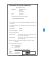
AVANTI CLIMB ASSISTANCE – TYPE VI User’s Manual and Installation Instructions AVANTI Climb Assistance – Type VI User’s Manual and Installation Instructions 4th edition: June 2010 Revision 4: 10/8/10 Manufacturer: AVANTI Wind Systems A/S Høgevej 19 3400 Hillerød · Denmark P: +45 4824 9024 F: +45 4824 9124 E: [email protected] I: www.avanti-online.com Sales & Services: Australia Avanti Wind Systems PTY LTD China Avanti Wind Systems Denmark Avanti Wind Systems A/S Germany Avanti Wind Systems GmbH Spain Avanti Wind Systems SL UK Avanti Wind Systems Limited USA Avanti Wind Systems, Inc. P: +61 (0) 7 3902 1445 P: +86 21 5785 8811 P: +45 4824 9024 P: +49 48142 1570 P: +34 976 149 524 P: +44 0 1706 356 442 P: +1 (262) 641-9101 EC-Declaration of Conformity for Machinery Directive 2006/42/EC, Annex II, A Manufacturer: Avanti Wind Systems A/S Høgevej 19 DK-3400 Hilllerød Phone: Fax: +45 4824 9024 +45 4824 9124 herewith declares that the model of the following machinery Type: AVANTI Climbing Assistance OPS. VI - is in conformity with the provisions of the Machinery Directive 2006/42/EEC as amended at the time of the declaration - is in conformity with the provisions of the following additional EC-directives as amended at the time of the declaration - Low-Voltage directive 2006/95/EC Electromagnetic compatibility 2004/108/EC 3 conform to the following standards: EN ISO 12100-1:2005 Safety of machinery -- Basic concepts, general principles for design Part 1: Basic terminology, methodology EN ISO 12100-2:2005 Safety of machinery -- Basic concepts, general principles for design Part 2: Technical principles EN 60204-1: 2006 Safety for machinery; Electrical equipment of machinery; Part 1: General requirements; - Reponsible for documentation: Germán Sacramento Address: Los Angeles 88 Nave 1 ES-50196 La Muela Phone: +34 976 14 95 24 Date: Date of the declaration for the machine specified above Signature: Name: Identification: Germán Sacramento Technical Director Signature: www.avanti-online.com R01 - 01/03/2010 Limited Warranty AVANTI Wind Systems A/S warrants that commencing from the date of shipment to the Customer, and continuing for a period of the longer of 365 days thereafter, or the period set forth in the standard AVANTI warranty, the AVANTI Climbing assistance (“Product”) described in this Manual will be free from defects in material and workmanship under normal use and service when installed and operated in accordance with the provisions of this Manual. 4 This warranty is made only to the original user of the Product. The sole and exclusive remedy and the entire liability of AVANTI under this limited warranty shall be, at the option of AVANTI, a replacement of the Product (including incidental and freight charges paid by the Customer) with a similar new or reconditioned Product of equivalent value, or a refund of the purchase price if the Product is returned to AVANTI, freight and insurance prepaid. The obligations of AVANTI are expressly conditioned upon return of the Product in strict accordance with the return procedures of AVANTI. This warranty does not apply if the Product (i) has been altered without the authorization of AVANTI or its authorized representative; (ii) has not been installed, operated, repaired, or maintained in accordance with this Manual or other instructions from AVANTI; (iii) has been subjected to abuse, neglect, casualty, or negligence; (iv) has been furnished by AVANTI to the Customer without charge; or (v) has been sold on an “AS-IS” basis. Except as specifically set forth in this Limited Warranty, ALL EXPRESS OR IMPLIED CONDITIONS, REPRESENTATIONS AND WARRANTIES, INCLUDING, BUT NOT LIMITED TO, ANY IMPLIED WARRANTY OR CONDITION OF MERCHANTABILITY, FITNESS FOR A PARTICULAR PURPOSE, NON-INFRINGEMENT, SATISFACTORY QUALITY, COURSE OF DEALING, LAW, USAGE OR TRADE PRACTICE ARE HERBY EXCLUDED TO THE MAXIMUM EXTENT PERMITTED BY APPLICABLE LAW AND ARE EXPRESSLY DISCLAIMED BY AVANTI. IF, PURSUANT TO ANY APPLICABLE LAW, TO THE EXTENT AN IMPLIED WARRANTY CANNOT BE EXCLUDED AS PROVIDED IN THIS LIMITED WARRANTY, ANY IMPLIED WARRANTY IS LIMITED IN TIME TO THE SAME DURATION AS THE EXPRESS WARRANTY PERIOD SET FORTH ABOVE. BECAUSE SOME STATES DO NOT PERMIT LIMITATIONS ON THE DURATION OF IMPLIED WARRANTIES, THIS MAY NOT APPLY TO A GIVEN CUSTOMER. THIS LIMITED WARRANTY GIVES CUSTOMER SPECIFIC LEGAL RIGHTS, AND THE CUSTOMER MAY HAVE OTHER LEGAL RIGHTS UNDER APPLICABLE LAWS. This disclaimer shall apply even if the express warranty fails of its essential purpose. List of content Introduction . . . . . . . . . . . . . . . . . . . . . . . . 6 Fig. 1 System outline . . . . . . . . . . . . . . . . . . . 6 Installation Manual 1. Motor installation: . . . . . . . 2. Electrical installation . . . . . . 2.1 Sensor installation . . . . . 2.2 Sensor test . . . . . . . . . 2.3 Motor cable installation . . 2.4 Power cable installation . . 3. Rope mounting . . . . . . . . . 3.1 Rope installation . . . . . . 3.2 Splicing the hauling rope . 4. Dismantling . . . . . . . . . . . 5. Marking . . . . . . . . . . . . . 6. Technical specifications . . . . . . . . . . . . . . . . . . . . . . . . . . . . . . . . . . . . . . . . . . . . . . . . . . . . . . . . . . . . . . . . . . . . . . . . . . . . . . . . . . . . . . . . . . . . . . . . . . . . . . . . . . . . . . . . . . . . . . . . . . . . User’s Manual 7. Purpose . . . . . . 8. Daily inspections . 9. Directions for use 10. Maintenance . . . 11. Yearly control . . . 12. Troubleshooting . . . . . . . . . . . . . . . . . . . . . . . . . . . . . . . . . . . . . . . . . . . . . . . . . . . . . . . . 16 . 16 . . 17 . 19 . 19 . 19 . . . . . . . . . . . . . . . . . . . . . . . . . . . . . . . . . . . . . . . . . . . . . . . . . . 7 8 8 8 9 9 9 9 12 15 15 15 Appendix A: Electrical control box overview . . . . . 20 Appendix B: Annual inspection . . . . . . . . . . . . . 21 5 System outline Introduction Fig. 1: System outline CAUTION: •The AVANTI Climbing Assistance installation and service may only be carried through by a competent person or an expert, authorized by Avanti. •Once a competent person or an expert installs, services, or in any other way alters the Climbing Assistance system, he alone is responsible for doing so in accordance with these User’s Manual and Installation Instructions. 6 DANGER: •Do not keep or store the hauling rope in direct sunlight. List of Signs: 1.Wall 2.Ladder 3.Ladder brackets 4.Person ascending 5.Harness 6.Spring-loaded base 7.Power supply 8.Electrical control box 9.Motor with drive wheel •Keep the hauling rope clean and free of oil, 10.Long guide roller grease and chemicals. 11.Resting platform 12.Hauling rope 13.Short guide roller •Only install an earth leakage 14.Platform reacts to pulsing DC. 15.Fall arrest device 16.Rope Clamp with Release- Strap 17.Rungs 18.Top fitting with top pulley circuit breaker that Installation Manual Fig. 2 Motor AVANTI recommends the following installation procedure. 1.Install the motor underneath the ladder. 2. Install top fitting with pulley, then guide rollers and hauling rope. 1. Motor installation: 1.Position the motor base with motor and drive wheel close to the ladder, on the opposite side of the fall protection rail (see fig. 2). In case the fall protection rail is positioned at the centre of the ladder, align the motor base as shown in fig. 3. This will leave the hauling rope approximately 30 mm off the fall protection rail to the right side (fig 3). The motor can be also aligned 30 mm off the left side of the fall protection rail if necessary. Once the motor is aligned, fasten it to the tower platform using the 4 units Ø8mm bolts supplied. Start with the closest bolt to the center of the ladder (the closest to the fall protection rail). If the motor is fixed to a concrete basement, use wall anchors for mounting. In case of further problems, contact Avanti for support. 2. Position the electrical control box close to the ladder. Fix the electrical control box to the platform using the angle fittings supplied (see fig. 4). Other options might be available out of the existing standard. Fig. 3 Motor position 7 Fig. 4 Fixed and portable electrical control box 2. Electrical installation 2.1 Sensor installation Fig. 5 Electrical control box open ! WARNING: adjust sensor while the system is unplugged. Proceed to adjust the sensor leaving a distance of 0,5-1,5 mm between the drive wheel and the sensor. After mounting the hauling rope, the sensor may need adjustment. Fig. 6 Sensor and sensor cable 8 2.2 Sensor test After installing the hauling rope turn on the power supply. Then, a diode on the sensor cable will light permanently. Pull down the rope. The sensor should register the movement of the drive wheel and another diode will start flashing on the sensor cable. The motor will start. If the movement is not detected, adjust the sensor position on the drive wheel according to the sensor installation. 2.3 Motor cable installation In case the connection of the motor was hardwired, connect the control box to the motor according to the wiring diagram supplied inside the control box: •Conductor 1 to U •Conductor 2 to V •Conductor 3 to W •Green-yellow conductor to earth connection •Conductors 4 and 5 to the motor thermal switch (the order of connection is not important) 3. Rope mounting 3.1 Rope installation 1.Get up to the ladder top, taking up the top fitting, top pulley, bolts, and one of the ends of the hauling rope. It is easier to bring the rope up the front side of the ladder and feed it down the rear. Fig. 8 Fig. 7 Motor connection The motor is connected in delta connection. 9 2.4 Power cable installation When the climbing assistant is fully installed, connect the electrical control box to the 230 V, 50-60 Hz (1 phase + N + earth) power supply according to the wiring diagram supplied inside the control box. Make sure the power supply is protected with: •Circuit breaker MCB 16 Amps Type C. •Residual current device RCD 30mA superimmunized. 2. At the top of the ladder, mount the top fitting as shown in fig. 8. The top pulley is positioned just off the rail centre using the holes in the top fitting so that it matches the bottom drive wheel position. Assemble two short guide rollers on the rungs just below the top pulley to make sure the right guiding of the rope. 3. Pass the rope through the top pulley and feed it down the rear of the ladder while descending. 4.Assemble a double guide roller with bearing on the first rung over the motor and a single guide roller with bearing on the second rung over the motor (see Fig. 9). Fig. 9 Single guide roller with bearing Fig. 10 Double guide roller with bearing 5.Down at the base platform, pass the rope between the guide rollers with bearing and the drive wheel. Tighten the rope slightly and fasten – do not splice it yet. Fig. 12 10 6.Mount the rest of the rope guide rollers on the rear side of the ladder. The guide rollers function is to prevent the rope from rubbing on the platforms and resting platforms. Use a short guide roller at every tower platform (Fig. 11) and a long guide roller at every ladder resting platform (Fig. 10). There are available protected guide rollers to prevent trapping (Fig. 12). 7. After having mounted all the rollers and motor, loosen the tensioning spring (Fig. 13) and open the motor base plate as much as possible. Tighten the rope with 75 kg. Use a separate rope or a rope tensioner as shown in Figure 14 below. Leave the rope for 20 min. and then recheck the tension. The rope has most likely stretched. Then tighten it again. Repeat this process until the rope does not stretch any more. Fig. 11 8.Cut off the excess rope, leaving an overlap of 50 cm. These 50 cm are needed for the splicing. Fig. 14 9. Splice the rope as described in section 3.2. 10. Tighten the spring on the motor base. The final length of the spring must be 60 mm. 11. After mounting the hauling rope, test the sensor as described in section 2.2. Fig. 13 11 3.2 Splicing the hauling rope 1.For the rope splicing use the supplied splicing needle. 7. Insert the splicing needle into the red rope not less than 250 mm from rope-end. Fig. 18 2.Make sure the rope is properly stretched. 3.For clarifying the splicing process one rope-end will be marked with red tape and the other one with black tape. 4.Seal one rope-end with red tape. On the same rope place a red tape mark at minimum 250 mm from rope-end. 5.The other rope-end should be sealed and marked with black tape. 12 8.Feed the full length of the splicing needle through the red rope. Fig. 19 Push Push Fig. 15 min 250 mm 9.Take the splicing needle out of the red rope. Fig. 20 6.Insert the black rope-end into the Ø10mm splicing needle. Make sure the rope-end is firmly placed inside the needle and is securely in the needle slot.. Fig. 16 Fig. 17 10.Remove the splicing needle. Pull the black rope through the red rope until the black mark passes the red mark. Fig. 21 13.Now feed the red rope-end into the black rope as follows. 14.Insert splicing needle into black rope as close to the black rope mark as possible. Fig. 25 11.With your right hand hold together the red and black rope marks. Use your left hand for sliding the red rope over the black rope. 15.Fasten the red rope-end into splicing needle. Fig. 22 Hold Fig. 26 13 Pull Fig. 23 16.Feed the splicing needle through the black rope along the full length of the splicing needle. Fig. 27 12.The black rope-end should be hidden inside the red rope. The black mark should just be visible. Fig. 24 17.Take the splicing needle out of the black rope. Fig. 32 Fig. 28 18.Pull the red rope as far as possible . 20. Finally stretch the rope by pulling the outer rope from the splice point towards the ends. This assures a snug splice join. Fig. 29 Fig. 33 Fig. 30 14 19.Hold the splice point with your left hand and then pull the black rope back over the red rope so that the red rope gets trapped inside the black rope. Fig. 31 Hold Pull 4. Dismantling 6. Technical specifications Remove the rope, followed by the guide rollers, top pulley, motor, and electrical control box. Dispose according to municipal regulations. Power supply: Standard: 230V, 50-60 Hz AC (1 phase + N + earth) Option: 110V, 60 Hz AC (1 phase + N + earth) Electrical protection: Circuit breaker MCB 16 Amps Type C. Residual current device RCD 30mA superimmunized. 5. Marking Fig. 34 Product marking Maximum current: 3,2 A ± 10% Rated current consumption: 2,1 A – 2,5 A ± 10% Adjustable lifting capacity approx: Fig. 35 Quick guide Speed: 30 m/min without load, adjusts automatically to the climber speed. AVANTI Climbing assistance AVANTI Sistema de ayuda a la ascensión s 5SERMUSTBEATLEASTYEARSOLD s %LUSUARIODEBETENERALMENOSA×OS s 5 SERMUSTHAVEABODYWEIGHTOFMINIMUM KG,B s % LDISPOSITIVONOPUEDESERUTILIZADOPORPERSONASCONUN PESOINFERIORA+GLBS s 5SEONLYORIGINAL!6!.4)ROPECLAMP s 3 ØLOSEPUEDEUTILIZARCONJUNTAMENTECONUNSISTEMAANTI CAIDA s !LWAYSUSEFALLPROTECTIONEQUIPMENT00% s $ONOTUSETHEDEVICEMORETHANONEPERSONAT THESAMETIME The Climbing Assistance does not replace fall protection equipment (P.P.E.). )NSTRUCTIONS #HECKROPETENSIONSPRINGONMOTORBASE If spring length is more than 60 mm, the rope needs tensioning. See manual for tensioning method. 45541072 Quickguide climb EN/DE 35 – 45 kg #HECKIFGREENLIGHTONMOTORWHEELCASINGIS ON If not: connect to the power supply and/or turn on the red switch on the grey control box. Standard: -10ºC - +55ºC Option: -40ºC - +55ºC Weight: Motor: Control box: Hauling rope Ø12mm: Approx. 68 g/m Gear oil: 0,7 liters Mobil SHC 629 s % LDISPOSITIVONOSEPUEDEUSARPORMÉSDEUNAPERSONA SIMULTÉNEAMENTE % LDISPOSITIVODEAYUDAALAASCENSIØNNOSUSTITUYEAL SISTEMAANTICAÓDALÓNEADEVIDA )NSTRUCCIONES #ONTROLARELMUELLETENSORDELCABLEENLABASEDELMOTOR Si la longitud es superior a 60 mm, tensar el cable. Consultar en el manual las instrucciones para tensar el cable. #OMPROBARSILALUZVERDEENLARUEDAMOTORESTÉ ENCENDIDA En caso contrario: conectar el dispositivo a la red y/o encenderlo desde el botón rojo de la caja de control !DJUSTPULLFORCEONGREYCONTROLBOXTO !JUSTARLAFUERZADEARRASTREDEADESDELACAJADE CONTROL #ONNECT0ERSONAL0ROTECTIVE%QUIPMENT00% ASPRESCRIBEDBYMANUFACTURER 5TILIZARELSISTEMAANTICAÓDASEGÞNLASINSTRUCCIONESDEL FABRICANTE &ASTENROPECLAMPCARABINERONHARNESS #ONECTARELCÉNCAMOALARNÏS &ASTENROPECLAMPONCLIMBINGASSISTANCEROPE #ONECTARELCÉNCAMOENLACUERDADEARRASTREDELSISTEMA 0ULLCLIMBINGASSISTANCEROPETOACTIVATEMOTOR 4IRARDELACUERDAPARAACTIVARELMOTOR 8. STOP – stand still for 5 seconds. $ETENERSESEGUNDOS !FTERUSETURNOFFTHEPOWERSUPPLY $ESPUÏSDELUSODESCONECTARLAALIMENTACIØNELÏCTRICA 45541073 Quickguide climb EN/ES Working temperature: 15 27 kg 12 kg User’s Manual 7. Purpose CAUTION: •A competent person is a person who has fully read and understood these Climbing Assistance User’s Manual and Installation Instructions. •The AVANTI Climbing Assistance installation and service may only be carried out by a competent person or an expert. •Once a competent person or an expert installs, services or in any other way alters the Climbing Assistance system, he alone is responsible for doing so in accordance with these User’s Manual and Installation Instructions. 16 DANGER: •Do not store the hauling rope in direct sunlight. •Keep the hauling rope clean and free of oil, grease and chemicals. •The power supply must not be equipped with an earth leakage circuit breaker that does not also react to pulsing DC as this will cause operational problems. Intended use The AVANTI Climbing Assistance is intended for helping personnel to ascend and descend fixed ladders, by relieving them from 35kg to 45 kg of its weight. Not suitable for •Not suitable for lifting tools or parts. •Not suitable for people below the age of 18 or people below the weight of 55 kg. •Not suitable for multiple users at the same time. •Not to be fastened to body parts or cloth. The Climbing Assistant is not a fall protection device. Always wear proper fall protection equipment (P.P.E.) Use original parts. No warranty is provided against damage resulting from reconstruction or modification of equipment, or use of nonoriginal parts. Functionality The system includes a motor, a continuous hauling rope, an electrical control box and a Rope Clamp with Release-Strap. Hook on to the hauling rope using the Rope Clamp with Release-Strap and activate the motor by pulling the hauling rope. A sensor on the drive wheel then registers the movement and starts the motor. The hauling rope then pulls with the pre-adjusted force (e.g. 40 kg.) regardless of the pace and direction of climb. Stop the rope in the same position for 3 seconds, then the sensor will register that the motion has stopped, and the pulling force fades out. 8. Daily inspections Check the rope tension spring on the motor base (see Fig. 36). If spring length is more than 60 mm, the rope needs tensioning. Compress the spring using a spanner. If this does not tighten the rope sufficiently, a rope shortening is needed. See Installation Manual section 3.2. Fig. 36 9. Instructions for use Before use, read these instructions. For use do as follows: 1. Perform the daily inspection described above. 2.Check if the LED diode on motor wheel guard lights. If not: connect to the power supply and/ or turn on the On / Off switch on the electrical control box. Assure the rope is aligned on the guide rollers and on the drive wheel (see Fig. 37). The rope can be placed on both right and left side. Fig. 37 3.Adjust the pulling force (1 to 10) on the electrical control box (Fig. 38). Depending on the rope length, it is equivalent to approximately 35kg - 45kg. Fig. 38 17 4.Connect harness and fall protection device (P.P.E) as prescribed by manufacturer. If anything abnormal is observed, take climbing assistance out of use. Repair the problem before continue to use the system. 5.Fasten the Rope Clamp with the Release- Strap carabineer to the harness. 6. Fasten the Rope Clamp with Release-Strap on the climbing assistance rope (Fig. 39). It has to be anchored above the fall arrest attachment of the centered chest attachment of the fully body harness (Fig. 40). Fig. 39 Rope Clamp with Release-Strap 7. Pull down the climbing assistance rope to activate motor. The rope will start pulling the climber up, relieving the weight previously set. The system will keep a continuous pulling force, following the climber’s pace. 18 8.Keep still for 5 seconds to stop the system. The climber can now detach the Rope Clamp with Release-Strap from the rope. CAUTION: Do not let the Release- Strap attached to the rope anytime. 9. After use, turn off the power supply and unplug it from the power socket. ! WARNING! When using the climbing assistance keep your fingers and other body parts, clothes, etc. away from the hauling rope, drive wheel, guide rollers and pulley. NOTE! The main switch must not be connected/ disconnected several times in rapid succession. Doing so may damage the electrical installation. Fig. 40 10. Maintenance The AVANTI Climbing Assistance is mainly maintenance free. Perform daily inspection as prescribed above and take action if any abnormalities were found. 11. Yearly control Once a year a competent person or an expert authorized by Avanti must inspect the climbing assistance. If not, this will void the warranty. AVANTI runs “Fall Protection Expert classes” on regular basis. If interested, contact AVANTI. CAUTION! Before servicing the Climb Assistance System, unplug the power supply and wait for at least 1 minute. Yearly control: 1.Assure all the bolts and nuts are tight (on motor, electrical control box, guide rollers, and top fitting). 2.Assure that the compression spring is compressed to L = 60mm (see Daily inspections section 8). 3.Gearbox oil: Change the gearbox oil every 3 years (see section 6, Technical Specifications). The date of last oil replacement is recorded in the Yearly Control Template, Appendix B. 4.Damaged parts should be replaced once they show signs of wear (on drive wheel, hauling rope, etc.). If only a section of the hauling rope needs replacement, insert a new section where it is damaged. 12. Trouble shooting Breakdown: The system doesn’t start by pulling down the hauling rope. Cause: Solution: Power supply is off or unplugged. Turn on the power supply. Plug the power supply to the power outlet. The rope is stuck. Find the blocking factor and remove it. The sensor light is off. Check the control box connections according to the wiring diagram. Check the sensor connection. The sensor light color doesn’t change when the drive wheel turns. The sensor is not adjusted. Adjust sensor as described in section 2.1 sensor installation. 19 Breakdown: Motor and drive wheel turn, however the hauling rope doesn’t move. Cause: Solution: The hauling rope is not properly tensioned and it slips around the drive wheel. Check whether the spring is compressed to approximately 60 mm long. If not, adjust rope tension as specified in section 8 Daily inspections. The hauling rope and/or the drive wheel is worn. Replace the worn components. Breakdown: The pulling force is too small Cause: Solution: The motor is not connected in delta / triangle connection Check wiring at the motor connection box. Perform wiring according to delta / triangle connection. Appendix A: Electrical control box overview 380 MM -U1 1380.500 380 MM -U13 40 MM BOTTOM PULLING FORCE ADJUSTMENT On PE PE PE PE -R16 210 MM I Off O M20 M20 M16 -W13 -W11 -W17 -A16 80 MM 120 MM 20 75 MM 380 MM 60 MM ECM GUIDE SENSOR POWER SUPPLY 135 MM MOTOR 135 MM Australia Avanti Wind Systems PTY LTD Unit 15 / 160 Lytton Road Morningside 4170 · Queensland P: +61 (0) 7 3902 1445 China Avanti Wind Systems Building 14 · Weishi Industrial Park No. 599 Zhongxin Road · Dagang Town Songjiang District · 201614 Shanghai P: +86 21 5785 8811 · F: +86 21 5785 8815 Denmark Avanti Wind Systems A/S Høgevej 17-19 · 3400 Hillerød · Denmark P: +45 4824 9024 · F: +45 4824 9124 Germany Avanti Wind Systems GmbH Weddingstedter Strasse 52 · 25746 Heide P: +49 481 42 15 70 - 0 · F: +49 481 42 15 70 - 29 Revision 4: 10/8/10 46240002 - Climb Assistance Manual EN 4th Edition: June 2010 Spain Avanti Wind Systems SL · Poligono Industrial Centrovia Calle Los Angeles No 88 nave 1 · 50196 La Muela P: +34 976 149524 · F: +34 976 149508 UK Avanti Wind Systems Limited Caldershaw Business Centre · Unit 29 Ings Lane · Rochdale · OL12 7LQ P: +44 0 1706 356 442 USA Avanti Wind Systems, Inc. 5150 S. Towne Drive · New Berlin · Wisconsin 53151 P: +1 (262) 641-9101 · F: +1 (262) 641-9161 India Avanti Wind Systems India Private Ltd Indus Valley’s Logistic Park · Unit 3 · Warehouse No. G-2 Ground Floor · Vellala Street · Mel Aiyanambakkam Chennai 600095 · Tamil Nadu I: www.avanti-online.com · E: [email protected]