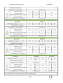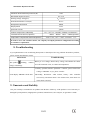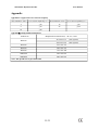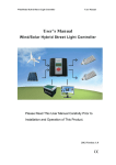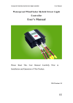
1
Wind/Solar Hybrid Controller User Manual User’s Manual Wind/Solar Hybrid Controller Please Read This User Manual Carefully Prior to Installation and Operation of This Product. 2014 V1.0 Wind/Solar Hybrid Controller User Manual Notices 1) Battery reverseconnection is forbidden. 2) Battery virtual connection or damage is one main factor of malfunction. Please check battery voltage and connection status weekly, clear rust on positive, negative terminal in time; use lead terminal if available. 3) If the malfunction is not easy to eliminate or reason unclear, please write down the phenomenon in detailed record, and contact manufacturer for help in time. Installation Environment 1) The equipment should be installed indoor where is wellventilated. 2) Avoid exposing the apparatus under direct sunshine, exposure, rain, moist, acid mist and dust. 3) Allow at least 20 inches (0.5 m) distance from battery. 4) Ambient Temperature is 20~+55℃; Ambient Humidity is 35 ~85%RH, no condensing. 5) Do not install the equipment in a compartment with flammable liquids, such as gasoline, or explosive vapors. Be ware of the flame and the spark. 1. General Description The wind/solar hybrid controller is an intelligent control device which can control wind turbine and solar panel at the same time, specially designed for highend wind/solar hybrid system and also suitable for wind/solar hybrid power system and wind/solar hybrid monitoring system. It is used to control the wind generator and solar panel to charge the batteries safely and efficiently. With decent appearance, easy operation, visual LCD display and perfect protection functions, the apparatus has high charge efficiency, low noload loss. The wind/solar hybrid controller is the core component of the offgrid power generation system. The performance of the controller will impact the life and the stability of the whole system, especially the lifespan of battery banks. 1/11 Wind/Solar Hybrid Controller User Manual 2. Model Specification Product Name WWS Wind solar hybrid controller Rated Input Power Rated Battery Voltage Optional Function Feature 06 0.6 kW 24 24V N Normal 00 Normal 10 1kW 48 48V L Low Voltage Charge 01 RS232 20 2kW 96 96V D Buck oltage Charge 02 RS485 30 3kW 120 120V B Economic 04 Solar Dumpload Separately 50 5kW 220 220V S Microcurrent Charge 10 Wind Turbine Single Phase DC 11 RS232 Wind Turbine Single Phase DC, RS232 12 RS485 Wind Turbine Single Phase DC, RS232 XX Other 100 200 10kW 240 240V 20kW Remark: Microcurrent Charge Function is only available for system no more than 3kW Power running with Battery Banks no more than 48V. E.G.:WWS2048L01 Rated Output Power: 2kW Rated Battery Voltage: 48V With Low Voltage Charge and RS232 communication function 2/11 Wind/Solar Hybrid Controller User Manual 3. Performance Description ² Reliability:Intelligentized, modularized design, simple mechanism, powerful functions. With industrial range superior components and strict production technology, the controller can be used in relatively bad working environment and has reliable performance and long lifespan. ² PWM Stepless Dumpload Mode: dump residual power with division into thousands of stages. It can dump residual power while charging battery banks, which is benefit to effectively extend battery longevity. ² Voltage Limiting and Current Limiting Charge Mode: When battery voltage exceeds the preset floating voltage point, the controller will adopt PWM voltage limiting charge mode. It dumps the excess energy. When wind turbine charging current exceeds preset brake current point, the controller will automatically start brake to protect battery banks. ² LCD Display Function: LCD screen can display system status and parameters via visual digital and graphic form. Such as: battery voltage, wind turbine voltage, PV voltage, wind turbine current, PV current, wind turbine power, PV power, battery power status etc. ² Perfect Protection Functions: Battery over charge protection, Battery over discharge protection, Battery antireserve connection protection, wind turbine currentlimiting charge, automatic brake, manual brake; solar antireverse charge protection, solar antireverse connection protection, lightning protection, etc. (Note: Following optional functions are valid only for controllers which have these functions) ² Optional Remote Communication Function: The software can monitor realtime system running status, which contain all the parameters on the LCD screen. Through the software, users can not only set and adjust relevant parameters, but also can control the wind turbine and load running status, and alarm while malfunction happens. ² Optional Low Voltage Charge Function: Boost module is added in the controller to help wind turbine charge battery banks even in low wind or the wind turbine rotates in low speed. User can adjust the admittance value and start charge voltage via software according to different wind turbine parameters. 3/11 Wind/Solar Hybrid Controller User Manual ² Optional Drycontact signal Function: When the battery is reaching setting value, the controller will automatically output drycontact signal. ² Optional Temperature Compensation Function: The controller can adjust the unload voltage according to different ambient temperature so that the battery charge is in the best efficiency. ² Optional SD card Function: With SD card, controller store system history data when the controller disconnected with PC. ² Optional Wind Speed Detection Function: The controller can detect realtime wind speed when it is matched with appointed anemometer. User can read the realtime wind speed via monitoring software. ² Optional Microcurrent Charge Function: When the wind turbine input voltage reaches to the preset value, the controller will produce the microcurrent charge for the battery. ² Optional Wind Turbine Rotate Speed Detection Function: User can read the realtime wind turbine rotate status via monitoring software. ² Optional DC Output Function: DC output offers power for DC load, with various control modes for choice, including: Constant on; Constant off; Constant halfpower; lightcontrol on, lightcontrol off; lightcontrol on, timecontrol off; lightcontrol on, timecontrol halfpower, lightcontrol off; lightcontrol on, timecontrol halfpower, timecontrol off. Via LCD buttons, users can set three output control modes: constant on; lightcontrol on, lightcontrol off; lightcontrol on, timecontrol off. 4. Installation Flow Remark: Users should connect according to the following corresponding connection: PIC A 4/11 Wind/Solar Hybrid Controller User Manual PIC B PIC C PIC D User should connect and operate all parts according to following procedures after wind turbine, solar panel and external circuit constructions are finished. Step 1. Check the package and then check the controller for damage after unpacking. Damaged controller cannot be installed in the system. Step 2. For controller whose dumpload box is separated, please connect dumpload box to the “DUMP LOAD” terminals of the controller. Step 3. Connect battery positive pole to the positive (+) “BATTERY” terminal, Connect battery 5/11 Wind/Solar Hybrid Controller User Manual negative pole to the negative () “BATTERY” terminal with copper core cable. (Note: Although the controller has antireverse connection protection function, wrong polarity of battery shall be forbidden! Please refer to Appendix I for copper wire over current capability.) Step 4. Connect the wind turbine output lines to the “WIND INPUT” terminals in condition of wind turbine in actionless or low speed. Step 5. Connect solar panels to the “SOLAR INPUT” terminals. Step 6. Check all connection is proper and firm or not. Step 7. If the controller has communication function, user can read and set relevant parameters via software. Step 8. User can set relevant parameters through LCD buttons. 5. LCD Display Instruction and Button Specification 5.1 LCD Display Instruction 1) Wind turbine symbol. 2) Day symbol. 3) Night symbol. Battery symbol, inner strip graph indicates the battery power status. Five inner horizontal strips display indicates the battery is full. The symbol shall be flashing when the battery is overdischarge, flashing will not stop until battery voltage recover. The symbol shall be flashing when the battery is over charge, flashing will not stop until battery voltage recover. 4) Parameters display symbol. Each system parameters are displayed via visual digit and graph. 5) Press the "Enter" key and "Esc" button at the same time, LCD displays the symbol which indicates wind turbine in brake status. Wind turbine will stop rotating or running in 6/11 Wind/Solar Hybrid Controller User Manual low speed under brake status. Press the "Enter" key and "Esc" button at the same time under brake status, the symbol will disappear and brake status is released. In normal situation, the wind turbine shall be in running status rather than brake status. 5.2 Button Specification LCD backlight will be on after pressing any button. The backlight will go out to save power if there is no button operation for 10 seconds. ² " ": Up/ Increase. In browsing status, press to check the previous parameter. In setting window, press this button to check the next adjustable parameter or increase the value of current parameter. ² " “: Down/Decrease. In browsing window, press to check the next parameter. In setting window, press this button to check the previous adjustable parameter or decrease the value of current parameter. ² "Enter": Set/Confirm. In browsing window, press "Enter" to access setting window. In setting window, press this button to save parameters and return back to browsing window. ² "Esc": Cancel/Manual reset. In setting window, press "Esc" to return to browsing window without saving the modified parameters. 5.3 Parameters Browsing 1) When power is on, the LCD is under browsing window and displays battery voltage: XX.X V; 2) In browsing window, LCD will circularly display the following parameters by pressing " " button and " " button. 7/11 Wind/Solar Hybrid Controller User Manual 6. Monitoring Software (Optional) The monitoring software is specially developed for the controllers that we produced, the following are the part functions which can be realized via the software, more information please refer to our software user manual. a) Remote monitoring and parameters configuration for different controller models. b) Big database system capacity. c) The controller can network according to RS482 bus, GPRS, Ethernet. d) History data Inquiry. 7. Technical Data Parameters WWS0648B Rated Battery Voltage(V)(VB) Rated Wind Power (kW) PW 48 0.6 Dimensions (L ×W ×H) (mm) Admittance Value Low Voltage Charge Function (Factory Default) 1 205×150×82 24 48 1 1 424×423×170 / 10/15 10/60 8 / 4 8 220×150×82 / 423×305×170 (Factory Default) (V) Parameters Rated Battery Voltage(V)(VB) WWS10 5/60 Wind Turbine Start Charge Voltage Dimensions (L ×W ×H) (mm) WWS1048B WWS20 48 8/11 96 120 220 240 Wind/Solar Hybrid Controller User Manual Rated Wind Power(kW)PW 2 Dimensions (L ×W ×H) (mm) 424×423×170 Admittance Value Low (Factory Default) Voltage Wind Turbine Start Charge Voltage Charge (Factory Default) (V) Function Dimensions (L ×W ×H) (mm) 10/30 10/150 10/150 5/300 8 20 20 40 423×305×170 Parameters Rated Battery Voltage(V)(VB) WWS30 48 96 120 Rated Wind Power(kW)PW Admittance Value (Factory Default) Voltage Charge Function Wind Turbine Start Charge Voltage (Factory Default) (V) 523×423×170 10/30 10/150 10/150 5/300 5/300 8 20 20 40 40 220 240 Dimensions (L ×W ×H) (mm) 423×305×170 Parameters Rated Battery Voltage(V)(VB) WWS50 48 96 120 Rated Wind Power(kW)PW 5 Dimensions (L ×W ×H) (mm) Admittance Value Low Voltage Charge Function (Factory Default) Wind Turbine Start Charge Voltage (Factory Default) (V) 423×305×170 10/30 5/75 5/75 5/300 5/300 8 20 20 40 40 Dimensions (L ×W ×H) (mm) 423×305×170 Parameters Rated Battery Voltage(V)(VB) Low Voltage Charge Function 240 3 Dimensions (L ×W ×H) (mm) Low 220 WWS100 120 220 WWS200 240 220 240 Rated Wind Power(kW)PW 10 10 Dimensions (L ×W ×H) (mm) 423×305×170 423×305×170 Admittance Value (Factory Default) Wind Turbine Start Charge Voltage (Factory Default) (V) 5/75 5/300 5/300 5/300 5/300 20 40 40 40 40 Dimensions (L ×W ×H) (mm) 423×305×170 Note: The specific size to prevail in kind, / means no such product. 9/11 423×305×170 Wind/Solar Hybrid Controller User Manual Maximum Wind Turbine Input Power(W) 1.5PW Rated Solar Input Power(W) PW×3/10 Floating Charge Voltage(V) VB ×14.5/12 Wind Turbine Brake Current(A) PW/VB Dumpload Control Mode PWM Display Mode LCD Quiescent Current ≤20mA Ambient Temperature & Humidity 20~+55℃/35~85%RH(Without Condensation) RS232 、RS485、 RJ45、 GPRS (Optional) Communication Function (Optional) Temperature Compensation Function(Optional) 4mV/℃/2V ,–35℃~+80℃ , Precision:±1℃ In order to serve our customers better, our company can adjust parameter configuration according to customer’s requirement. 8. Troubleshooting If your phenomenon is out of following descriptions or should you have any problems about these products, please contact manufacturer in time. Troubleshooting Phenomenon The symbol flashing, without Battery is overvoltage, check battery voltage, and whether the cables charge or discharge are wellconnected or not, reconnect all components. a) Firstly, open the software “parameter”“control”, please check if the setting is “BRAKE”. If yes, please cancel it. LCD display “BRAKE” all the time b)Secondly, Disconnect wind turbine, battery with controller successively. Reconnect them a few minutes later, then check if it comes back to normal. 9. Guarantee and Liability One year warranty is available for our product from the date of delivery. If the product is out of warranty or damaged by transportation, inappropriate operation, human factors, force majeure, no guarantee is made. 10/11 Wind/Solar Hybrid Controller User Manual Appendix Appendix I: Copper Wire Over Current Capacity Wire Diameter (mm²) Over current capability (A) Wire Diameter (mm²) Over current capability (A) 4 ≤20 16 ≤90 6 ≤30 25 ≤125 10 ≤50 AppendixⅡ : Dump load Box Dimension Product No. Dumpload box Dimension (L ×W ×H)(mm) WWS10 410×230×175 (24V System) 300×190×120 (48V System) WWS20 410×430×175 WWS30 540×430×175 WWS50 770×390×180 WWS100 520×430×675 WWS200 680×420×675 Note: The specific size to prevail in kind. 11/11