1
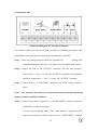
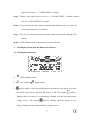
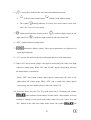
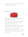
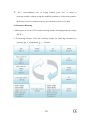
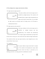
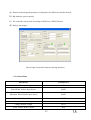
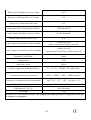
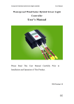
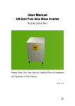
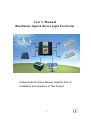
User’s Manual Wind/Solar Hybrid Street Light Controller Please Read This User Manual Carefully Prior to Installation and Operation of This Product. 1 1. Product Introduction The wind/solar hybrid street light controller is an intelligent apparatus which is specially designed for high-end small-scale wind/solar hybrid system and especially suitable for wind/solar hybrid street light system and wind/solar hybrid monitoring system. It can simultaneously control wind turbine and solar panel to charge battery safely and efficiently. With decent appearance, easy operation, visual LCD display and perfect protection functions, the apparatus has high charge efficiency, low no-load loss. The system operation shall be safe, stable and reliable. With high cost performance and long life-span, it has already been accepted by most customers. The wind/solar hybrid street light controller is the most critical part in the off-grid street light system, whose performance will affect the longevity and stability of the whole system, especially the longevity of battery. 2. Performance Description Reliability: Intelligentized, modularized design, simple mechanism, powerful functions. With industrial range superior components and strict production technology, the controller can be used in relatively bad working environment and has reliable performance and long life-span. PWM Stepless Dumpload Mode: When the power generated by wind turbine and solar panel exceed battery capacity, 2 the controller will release residual power. Common control mode is to dumpload all the power. However, the battery is not full actually. That all the power was consumed via resistors makes resource tremendously wasteful. Even with staging dumpload, it can be just divided into five to six stages, the effect is still unsatisfied. Our company adopts PWM (Pulse Width Modulation) stepless dumpload mode. In another word, the controller can dump residual power with division into thousands of stages. It can dump residual power while charging battery banks, which is benefit to effectively extend battery longevity. Voltage Limiting and Current Limiting Charge Mode: When battery voltage exceeds the pre-set dumpload voltage point, the controller will adopt PWM voltage limiting charge mode. It dumps the excess energy in order to extend the battery longevity. When wind turbine charging current exceeds pre-set brake current point, the controller will automatically start brake to protect battery. (e.g.: WWS06-48-N: If battery voltage exceeds charge shutoff voltage or wind turbine current exceeds wind turbine brake current, the controller will automatically start brake.) Two DC Outputs Mode: Each DC output has various control modes for choice, including: Constant on; Constant off; Constant half-power; light-control on, light-control off; light-control on, time-control off; light-control on, time-control half-power, light-control off; light-control on, time-control half -power, time-control off. Users can set three output control modes by LCD buttons: constant on; light-control on, light-control off; 3 light-control on, time-control off. LCD Display Function: LCD screen can display system status and parameters via intuitionistic digital and graphic form. Such as: battery voltage, wind turbine voltage, PV voltage, wind turbine current, PV current, wind turbine power, PV power, load current, output control modes, time control output shutoff hours, light control on/off voltage points, day or night indication, load status, battery over voltage/under voltage status etc. Perfect Protection Functions: Battery over charge protection, battery over discharge protection, battery anti-reverse connection protection; load short circuit, over load protection; wind turbine current limiting, automatical brake, manual brake protection; solar anti-reverse charge, solar anti-reverse connection; lightning protection etc. (Note: Following optional functions are valid only for controllers which have these functions.) Optional Remote Communication Function: The software can monitor real-time system running status, which contain all the parameters on the LCD screen. Through the software, users can not only set and adjust relevant parameters, but also can control the wind turbine and load running status, and alarm while malfunction happens. Optional Low Voltage Charge Function: Boost module is added in the controller to help wind turbine charge battery banks even in low wind or the wind turbine rotates in low speed. User can adjust the 4 admittance value and start charge voltage via software according to different wind turbine parameters. Optional By-pass Function: When the battery is under voltage, the controller will automatically switch to the utility grid to get power for driving load to ensure the continuity of the system. Optional Temperature Compensation Function: The controller can adjust the dumpload voltage according to different ambient temperature so that the battery charge is in the best efficiency. Optional SD card Function: With SD card, controller store system history data when the controller disconnected with PC. Optional Wind Speed Detection Function: The controller can detect real-time wind speed when it is matched with appointed anemometer. User can read the real-time wind speed via monitoring software. Optional Micro-current Charge Function: When the wind turbine input voltage reaches to the pre-set value, the controller will produce the micro-current charge for the battery. Optional Wind Turbine Rotate Speed Detection Function: User can read the real-time wind turbine rotate status via monitoring software. 5 3. Installation Flow (Connection Diagram of Controller Terminals) User should connect and operate all parts according to following procedures after wind turbine, solar panel and external circuit constructions are finished. Step 1 Check the package and then check the controller for damage after unpacking.Damaged controller is not allowed to be installed in the system. Step 2 Connect DC load to “DC OUTPUT” terminals: The first load should be connected to "+" and "-1" of the “DC OUTPUT” terminals, the second load should be connected to "+" and "-2" of the “DC OUTPUT” terminals. Step 3 Connect battery to “BATTERY” terminals with 6mm2 copper cables or above. (Note: The controller has anti-reverse connection protection function, but wrong polarity of battery shall be forbidden!) Step 4 Connect wind turbine output line to “WIND INPUT” terminals when the wind turbine is under static status or in low speed running status. If the wind turbine is single-phase DC output, just connect the positive pole line to(+) “WIND INPUT” terminal, 6 negative pole line to (-)”WIND INPUT” terminal. Step 5 Connect solar panel positive wire to (+) “SOLAR INPUT” terminal, negative wire to (-) “SOLAR INPUT” terminal. Step 6 If the controller has the remote communication function, user can read and set relevant parameters via software. Step 7 User can set relevant parameters and load output control modes through LCD buttons. Step 8 Check whether all the connections are correct and firm. 4. LCD Display Instruction and Button Specification 4.1. LCD Display Instruction 1) Wind turbine symbol. 2) Day symbol 3) Night symbol. battery symbol,inner strip graph indicates the battery power status. Five inner horizontal strips display indicates the battery is full. The symbol shall be flashing when the battery is over-discharge, flashing will not stop until battery voltage recover. The symbol shall be flashing when the battery is over charge, flashing will not stop until battery voltage recover. 7 4) Load symbol, indicates the load status and malfunction status. indicates load normal output The symbol indicates load without output flashing indicates over-load, users must remove extra load, click “Esc” key to recover output. 5) Light-control and time-control symbol. light-control off. It indicates light-control on and It indicates light control on and time control off. 6)“SET” symbol indicates setting status. 7) Parameters display symbol. Each system parameters are displayed via visual digit and graph. 8)“1 2” at lower left indicates the first load output and the second load output. 9)When “ON” and a certain voltage value appear concurrently, the value is the light control on voltage point. When “ON” and “LOAD” appear concurrently, indicates the output mode is constant on. When “OFF” and certain voltage values appear concurrently, the value is the light control off voltage point. When “OFF” and a certain time values appear concurrently, the time indicates hours of the time control off. 10)Press the “Enter” key and “Esc” key at the same time, LCD displays the symbol which indicates wind turbine in brake status. Wind turbine will stop rotating or running in low speed under brake status. Press the “Enter” key and “Esc” button at the same time under brake status, the symbol 8 will disappear and brake status is released. In normal situation, the wind turbine shall be in running status rather than brake status. 4.2. Button Specification LCD backlight will be on after pressing any button. The backlight will go out to save power if there is no button operation for 10 seconds. “ ”: Up/ Increase. In browsing status, press to check the previous parameter. In setting window, press this button to check the next adjustable parameter or increase the value of current parameter. “ ”: Down/Decrease. In browsing window, press to check the next parameter. In setting window, press this button to check the previous adjustable parameter or decrease the value of current parameter. “Enter”: Set/Confirm. In browsing window, press “Enter” to access setting window. In setting window, press this button to save parameters and return back to browsing window. 9 “Esc”: Cancel/Manual reset. In setting window, press “Esc” to return to browsing window without saving the modified parameters. In browsing window, the button is used as a manual reset key for load short circuit or over load. 4.3 Parameter Browsing 1)When power is on, the LCD is under browsing window and displays battery voltage: XX.X V; 2)In browsing window, LCD will circularly display the following parameters by pressing “ ” button and “ ” button. 10 LCD can display three output control modes as follows: 1) Light-control on, light-control off Left picture indicates the first load output mode is controlled by sunlight intensity. The controller will automatically have output at night, automatically stop output at day with this control mode. User can adjust the light control on and light control off voltage point via LCD button or communication software. 2) Light-control on, time-control off Left picture indicates the first load output mode is controlled by sunlight intensity and time simultaneously. The controller will automatically have output at night, automatically stop output when the time arrives at the pre-set “time control off” hours with this output control mode. The controller will also auto stop output when day comes though the pre-set “time control off time” doesn’t arrive. 3) Constant on Left picture indicates output control mode is constant on. The controller will constantly have output within 24 hours unless the battery is protected by over discharge protection, over charge protection or malfunctions occurred. 11 4.4 Parameter Setting User can set the first load and second load output control modes, and parameters by LCD button operation, such as: light control on voltage, light control off voltage, time control off hour value. When user needs to modify any specific parameters, go to browsing window by pressing “ ” or “ ”. Press “Enter” and access to corresponding setting window, then “SET” comes out on LCD. User can modify parameters or status by pressing “ ” or “ ". Press the "Enter" to save the modified parameters and get back to browsing window. Just press “Esc” and roll back to browsing window if user doesn’t need to save the parameters. 5. Monitoring Software (Optional) The monitoring software is specially developed for the controllers that we produced, the following are the part functions which can be realized via the software, more information please refer to our software user manual. 12 a) Remote monitoring and parameters configuration for different controller models. b) Big database system capacity. c) The controller can network according to RS482 bus, GPRS, Ethernet. d) History data inquiry (Street Light Controller Parameters Setting Interface) 6. Technical Data Parameters WWS04-12-N Rated Battery Voltage 12V Rated Wind Turbine Input Power 400W Maximum Wind Turbine Input Power 600W Rated Solar Input Power 150W Dumpload Start Voltage 13.5V Charge Shutoff Voltage 14.5V Wind Turbine Brake Current 40A 13 Battery Over Discharge Protection Voltage 10.8V Battery Over Discharge Recovery Voltage 12V Output Over Voltage Protection Value 16V Light Control On Voltage (Factory Default ) 1V【Adjustable】 Light Control Off Voltage (Factory Default) 1.5V【Adjustable】 Rated Output Current of Load 1 and 2 10A Load 1 Output Control Mode (Factory Default) 3 Modes Selection (Light Control On and Light Control Off) Load 2 Output Control Mode (Factory Default) 3 Modes Selection (Light Control On and Time Control 5 Hours Off) Dumpload Control Mode PWM Display Mode LCD Quiescent Current ≤20mA Ambient Temperature & Humidity Range -20~+55℃/35~85%RH(No Condensation) Communication Function (Optional) RS232 、RS485、 RJ45、 GPRS (Optional) Temperature Compensation Function(Optional) -4mV/℃/2V ,–35℃~+80℃ , Precision:±1℃ By-pass Function(Optional) Auto Switch Dimensions (L × W ×H) 142×150×82mm Net Weight 1.9kg In order to serve our customers better. Our company can adjust parameters configuration according to customer’s requirement. 14 7. Troubleshooting Problem The symbol flashing, no charge or discharge. Possible Cause and Solution Battery is over-voltage, check battery voltage, and whether the cables are well-connected or not, re-connect all components. The symbol flashing and no output. Battery is over-discharge and empty. Please use the battery after it is fully charged. Disconnect the battery and recover it with charger device if the battery is over discharge for a long time. The symbol flashing and no output. Overload. Please check the load, remove the extra or abnormal load, press "Esc" button to recover. flashing and no output. Short-circuit. Please check load and wiring, remove the short-circuit hazard or damaged load, press "Esc" button to recover. The symbol 1. LCD wire connection might be loose, please open controller case to check. 2. The fuse might be burnt due to the battery reverse connection, No LCD display. please open controller case to check. 3. Battery is empty or virtual connection, please check the battery voltage and examine whether the wire connection is firm or not. If your phenomenon is out of above descriptions or should you have any problems about these products, please contact our after sales service department or sales man to repair or replace. 8. Installation Environment Avoid operating the apparatus under direct sunshine, blazing sun, and rainy, moist, acid mist environment, etc. Keep the apparatus away from flammable and explosive gas or hazard, including flame and spark. 15 9. Guarantee and Liability One year warranty is available for our product from the date of delivery. If the product is out of warranty or damaged by transportation, inappropriate operation, human factors, force majeure, no guarantee is made. 16