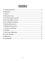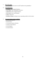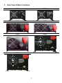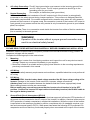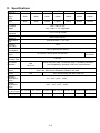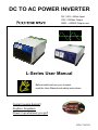
1
DC TO AC POWER INVERTER
12V / 24V / 48Vdc Input
115V / 230Vac Output
150W ~ 6000W Output cont.
L-Series User Manual
Before install and use your Inverter,
read the User Manual and safety instructions.
Cooler housing design!!
Anytime, Anywhere
Power it up wherever you go!!
VER.C/980720
CONTENTS
A. General Introduction ........................................................................................... 3
B. Application........................................................................................................... 3
C. Features ............................................................................................................... 3
D. Safety Instructions .............................................................................................. 3
E. Front View & Main Functions ............................................................................. 5
F. Rear View & Main Functions ............................................................................... 7
G. Pre-Installation Information ................................................................................ 8
H. Electrical Requirements ..................................................................................... 8
I. Installation Requirements .................................................................................... 8
J. Connection and Testing .................................................................................... 10
K. Operation ........................................................................................................... 11
L. Green Power Adjustment .................................................................................. 11
M. Trouble Shooting .............................................................................................. 12
N. Maintenance ...................................................................................................... 13
O. Specifications.................................................................................................... 14
-2-
A. General Introduction
We are experts in DC to AC Power Inverter and Solar Inverter. Our engineers are making use of
advanced technological design that results in an inverter that is more excellent, smarter and
easier to use than any other inverter with similar power ratings. We have been developed to
provide you with years of trouble free operation. We provide a Pure Sine Wave output with very
high quality power, often with less spikes and surges than grid-supplied power.
Please take a few minutes to read this manual carefully.
B. Application
Pure Sine Wave Power Inverters provide 150, 350, 650, 1200, 1800, 3000 and 6000 watts of
Pure Sine Wave AC power from a DC source.
C. Features
Capable of driving inductive loads, i.e., electric
tools and appliances
Does not affect other equipment like TV,
radio…etc
Standard specially-designed AC and DC line
filters
Specific chassis for harsh environments
No problem with microwave ovens
Standard low battery cut-off
Great overload performance
State-of-Art auto load sense
Pure sine wave at 50~60Hz
Lowest installation cost
Extremely efficient
Easily mounted
No noise
Microprocessor-based design with accurate
and stable frequency
Standard outputs adjustable 100~120Vac,
200~240Vac, 50/60Hz
Panel indicators for battery voltage & load level
(%)
Standard inputs 12V, 24V (48V Custom design)
Very low harmonic distortion, THD<3%
Quick response, standby functions
Very efficient stand-by circuit
Can be used anywhere
Simplified system design
Remote control unit
Green Power
Reliable
D. Safety Instructions
WARNING!
Before installing and using your inverter, read the Safety Instructions!
1.
General Safety Precautions
•
•
•
•
Do not expose the Inverter to rain, snow, spray, bilge or dust.
To reduce risk of hazard, do not cover or obstruct the ventilation openings.
Do not install the Inverter in a zero-clearance compartment. Overheating may result.
To avoid a risk of fire and electronic shock, make sure that existing wiring is in good electrical
condition and that wire is not undersized.
• Do not operate the Inverter with damaged or substandard wiring.
-3-
2.
Explosive Gas Precautions
This equipment contains components that can produce arcs or sparks. To prevent fire or
explosion do not install in compartments containing batteries or flammable materials, or in
locations that require ignition-protected equipment. This includes any space containing
gasoline-powered machinery, fuel tanks, or joints, fittings, or other connections between
components of the fuel system.
3.
Precautions When Working With Batteries
If battery acid contacts skin or clothing, wash immediately with soap and water. If acid gets into
eyes, immediately flood eyes with running cold water for at least 20 minutes and get medical
attention immediately.
• NEVER smoke or allow a spark or flame in vicinity of batteries or engine. Do not drop a metal
tool on the battery. The resulting spark or short-circuit of the battery may cause an explosion.
• Remove personal metal items such as rings, bracelets, necklaces, and watches when
working with a lead-acid battery. A lead-acid battery produces a short-circuit current
high enough to weld a ring or similar metal, causing a severe burn.
4.
Installation and Operation
To get the most out of the power inverter, it must be installed and used properly.
-4-
E. Front View & Main Functions
0150LN
0350LN
0650L
1200L
1800L
3000L
6000L
-5-
1.
2.
ON / OFF switch
Power ON/OFF switch, leave in the OFF position during installation.
LED INDICATION
• Over Volt: Over Voltage Protection.
• Over Temp.: Over Temperature Protection.
• Under Volt: Under Voltage Protection.
• Over Load: Over Load Protection.
• Power: Power ON.
• Run/Green Power: Indicates current operating condition of the inverter.
3.
AC outlet (Outlet sockets available)
• North America (GFCI )
• North America
• Continental European (Schuko)
• Australia / New Zealand
• United Kingdom
• Universal Socket
-6-
F. Rear View & Main Functions
0150LN
0350LN
0650L
1200L
1800L
3000L
6000L
-7-
1.
2.
Ventilation window
Do not obstruct; allow at least 1 inch for airflow.
Battery terminals
Connect to 12V / 24V / 48V battery or other 12V / 24V / 48V power source. (+) is positive, (-) is
negative. WARNING! Reverse polarity connection will blow internal fuse and may damage
inverter permanently.
WARNING! Shock Hazard!
Before proceeding Further, ensure that the Inverter is NOT connected
to any Batteries, and that all wiring is Disconnected from any electrical
Sources. Do not connect the output Terminals of the Inverter to an
incoming AC sources.
G. Pre-Installation Information
Before installing your inverter, please make sure that you have appropriately- sized batteries. A
battery that is too small will not allow the inverter to perform to its full specification.
H. Electrical Requirements
DC input voltage of the inverter must be the same as the battery bank voltage.
DC cabling must be connected to the correct polarity terminals of the battery bank
(Red = Positive, Black = Negative).
DO NOT extend the DC cable length to the inverter unless you are prepared to increase the
diameter of the cable. If this is necessary consult your supplier / installer for advice.
DO NOT connect AC power to the output of the inverter: THIS WILL DAMAGE THE INVERTER.
Between the inverter and any generator / mains supply, install a double-pole “break-before-make”
changeover switch, switching both line and neutral.
I.
Installation Requirements
1.
Where to install—The power inverter should be installed in a location that meets the following
requirements:
• Dry– Do not allow water to drip or splash on the inverter, free of salt or moisture-laden air.
• Temperature – Ambient air temperature should be between 0℃and 40℃.
• Safety–Do not install in a battery compartment or other areas where flammable fumes may
exist, such as fuel storage or engine compartments.
• Ventilation–Allow at least one inch of clearance around the inverter for airflow. Ensure the
ventilation openings on the rear and bottom of the unit are not obstructed. The installation site
should not be susceptible to temperatures in excess of 50°C.
• Dust-free–Do not install the inverter in an environment where either dust, wood particles or
other filings/shavings are present. These can pull into the unit blocking the cooling fan.
• Close to battery/batteries–Avoid excessive cable lengths (Mount the inverter between one
and two meters from the batteries) but do not install the inverter over or in the same
compartment as batteries. Use the recommended wire lengths and sizes. Do not mount the
inverter where it will be exposed to the gases produced by the battery. These gases are very
corrosive and prolonged exposure will damage the inverter.
• Wall-mount—Inspection and operation are more convenient if the unit is mounted at head
height and the DC cables hang naturally out of the way.
-8-
2.
3.
AC safety Grounding—The AC input ground wire must connect to the incoming ground from
your AC utility source. The AC output ground wire should go to the
grounding point for your loads.
(for example, a distribution panel ground bus)
Neutral Grounding
115V models: The neutral conductor of the AC output circuit of the Inverter is automatically
connected to the safety ground during inverter operation. This conforms to National Electrical
Code safety requirements. For models configured with a transfer relay, when AC utility power is
present and the inverter is in bypass mode, this connection (neutral of the inverter’s AC output to
input ground) is not present so that the utility neutral is only connected to ground at your breaker
panel, as required.
230V models: There is no connection made inside the Inverter from either of the line conductors
(line or neutral) to the earth ground.
WARNING!
Operation of the inverter without a proper ground connection may
result in an electrical safety hazard.
PLEASE READ THESE INSTRUCTIONS CAREFULLY BEFORE COMMENCING INSTALLATION
Installation should be performed by competent professional electrical/renewable energy installer, as
dangerous voltages can be present.
Complete the following steps in the order shown:
1.
Mounting
• Unpack your inverter from its shipping container and inspect the unit for any obvious transit
damage. Report any concerns immediately to your supplier.
• Mount the inverter to a suitable surface, paying close attention to the mounting requirements
previously mentioned in this manual.
2.
AC Wiring
Important: to satisfy warranty requirements and conditions, a qualified electrician must perform all
AC wiring.
3.
DC Wiring
IT IS ESSENTIAL that the battery bank voltage matched the DC input voltage rating of the
inverter. Damage to the inverter could result from improper voltage connections.
A battery fuse must be installed between the batteries and the inverter; appropriately sized
Motor-starting fuses or similar are recommend.
Before making any connections ensure that the inverter circuit breaker is in the OFF
position. Connect the inverter DC input cables to the battery terminal, the BLACK cable to
the negative battery terminal.
4.
Ground Fault Circuit Interrupters (GFCI’S)
Installations in Recreational Vehicles (for North American approval) will require GFCI protection of
all branch circuits connected to the AC output of the Inverter. In addition, electrical codes require
GFCI protection of certain receptacles in residential installations. While the output of the Inverter
is equivalent to the waveform provided by utilities, compliance with UL standards requires us to
test and recommend specific GFCI’s. State power has tested the following GFCI-protected 15A
receptacles and found that they functioned properly when connected to the output of the Inverter.
-9-
WARNING!
Do not operate the power inverter without connecting it to ground.
Electrical shock hazard may result.
5.
Making DC Wiring Connections
Follow this procedure to connect the battery cables to the DC input terminals on the inverter. Your
cables should be as short as possible (ideally, less than 10 feet / 3 meters) and large enough to
handle the required current, in accordance with the electrical codes or regulations applicable to
your installation. Cables that are not an adequate gauge (too narrow) or are too long will cause
decreased inverter performance such as poor surge capability, frequent low input voltage
warnings and shutdowns.
J. Connection and Testing
For a quick connection and performance check, please follow these guidelines:
1.
Unpack and inspect the power inverter, check to see that the power switch in the OFF position.
2.
Connect the DC POSITIVE cable to the Positive (POS+) terminal on the battery. Next, connect the
cable to the positive terminal on the inverter.
The connection to the negative (NEG-) terminal of the Inverter should be the last connection
made. A spark when making this final connection is normal.
WARNING!
Make sure all the DC connections are tight (torque to
9-10 ft-lbs,11.7-13Nm). Loose connections will
overheat and could result in a fire hazard.
3.
Before proceeding further, carefully check that cable you have just connected the positive
terminal of inverter to the positive terminal of the power source.
CAUTION!
Reversed polarity connections will blow a fuse in inverter and may permanently
damage the inverter. Damage caused by a reverse polarity connection is not
covered by our warranty.
4.
Connect the cable securely from the negative terminal of inverter to the negative terminal of the
power source.
WARNING!
You may observe a spark when you make this connection. Do not make this
connection in the presence of flammable fumes. Explosion or fire may result.
-10-
5.
6.
7.
Set the power switch to the ON position. Check the power and RUN / GREEN POWER LED
indicators on the front panel of the inverter source. If the LED is not lit, check your power source
and the connections to inverter. The other indicators should be off.
Set power inverter switch to the OFF position. The indicator lights may blink and the internal alarm
may sound momentarily. This is normal. Plug the test load into the AC receptacle on the front
panel of the inverter. Leave the test load switch off.
Set power inverter switch to the ON position and turn the test load on. The inverter should supply
power to the load. If you plan to measure the output voltage of the inverter, a meter such as
FLUKE 45, BECKMAN or other Digital Volt meter must be used.
K. Operation
To operate the power inverter, turn it on using the ON/OFF switch on the front panel. The power
inverter is now ready to deliver AC power to your loads. If you are operating several loads from
the power inverter, turn them on separately after the inverter has been turned on. This will ensure
that the power inverter does not have to deliver the starting currents for all the loads at once.
1. Controls and indicators
The ON/OFF switch turns the control circuit in the power inverter on and off. It does not disconnect
power from the power inverter.
The Inverter operates from an input voltage ranging from:
10 to 16 VDC for 12V models
20 to 32 VDC for 24V models
42 to 62 VDC for 48V models (By custom design only)
Peak performance for the inverter occurs when DC input voltage is in the Range of 10 volts to 16
volts for 12V models and 20 volts to 32 volts for 24V models, and 42 volts to 62 volts for 48V models,
from 150Watts up to 6000Watts.
2. Over voltage indicator
The over voltage indicator indicates that the power inverter has shut itself Down because its input
voltage higher than the detect voltage (12V / 24V / 48VDC versions).
3. Under voltage indicator
The under voltage indicator indicates that the power inverter has shut itself down because its input
voltage has been lower than detect voltage (12V / 24V / 48VDC versions).
4. Over temp indicator
The over temp indicator indicates that the power inverter has shut down because it has become
overheated. The power inverter may overheat because it has been operated at power levels above
its rating, or because it has been installed in a location which does not allow it to dissipate heat
properly. The power inverter will restart automatically once it has cooled off.
5. Overload indicator
The overload indicator indicates that the power inverter has shut itself down because its output
circuit has been short circuited or drastically overloaded. Switch the ON/OFF switch to OFF, correct
the fault condition, and then switch the ON/OFF switch back to ON.
L. Green Power Adjustment
Our inverter features automatic load-sensing, which allows the inverter to wait in Standby mode
until an AC load is switched ON. When an AC load appears the inverter will immediately start.
This feature conserves valuable battery energy as the inverter uses only about 10% of normal
power when in standby mode (standby is indicated by flashing green lamp). The amount of AC
power required to start the inverter can be adjusted, following the procedure below. Ensure
battery voltage is at nominal, i.e. 12V or 24V as appropriate for your inverter.
-11-
Adjust load sensitivity for green power mode as follows:
•
•
•
•
•
•
•
Turn OFF all AC loads, keeping the AC wiring connected. Some loads such as TVs must be
turned OFF at the power point as they can still represent a small load to the inverter.
Using a small screwdriver adjust the black plastic trim pot located to the right of the two lamps
below the power point. Turing this control fully clockwise will override the standby circuit and
keep the inverter ON all the time: this could be used if you have a very small load that must stay
ON at all times.
Adjust the pot until the lamp is steady green, then turn the pot back a little until the lamp flashes
green. Allow 10 seconds between adjustments for stabilization: clockwise is less sensitive;
counter-clockwise is increased sensitivity.
Note: the trim pot is extremely sensitive.
When the lamp flashes GREEN, the unit is in standby mode.
Turn on the smallest AC load attached to the inverter. The inverter should now deliver 240VAC,
and AC status lamp should be GREEN, However, if the lamp is ORANGE the sensitivity must
be increased by turning the control pot a little counter-clockwise.
Now turn OFF the AC load. The lamp should return to flashing GREEN, indicating that the
inverter is on standby. If this does not occur, reduce sensitivity by turning the control pot a little
clockwise and check again.
M. Trouble Shooting
AC output does not stay ON
Some AC loads may not large enough to hold the inverter ON. This condition is indicated by the inverter
turning off after every eight to ten seconds, then back on again. The AC Status lamp will also be flashing
orange.
There are two possible solutions:
Increase the sensitivity of the inverter by turning the Standby control slightly counter-clockwise
until the lamp shows steady green; Increase the amount of AC load on the inverter.
Inverter shuts down due to Over Temperature
Your inverter will safely provide the output power defined in the technical data section under the
conditions specified. If the inverter shuts down and indicates over temperature, it may be that you have
exceeded one of the parameters.
Check the following:
Ensure the inverter has adequate ventilation. Insufficient ventilation can severely restrict the power
output of your inverter.
Ensure that the true power rating of your appliance (including power factor) is less than the output
rating of your inverter.
Inverter shuts down when trying to start a load
A sudden surge in load, such as a motor starting, may cause the inverter to shut down. If this occurs;
Ensure the battery voltage is within specifications when the device is trying to start: if the voltage falls
too far, you may need to increase the size of your batteries.
If the battery voltage is ok then the inverter power output may be too small.
Common problems
1.
Television interference
Operation of the power inverter can interfere with television reception on some channels. If this
situation occurs, the following steps may help to alleviate the problem:
• Make sure that the chassis ground lug on the back of the power inverter is solidly connected to
the ground system of your vehicle, boat or home.
-12-
• Do not operate high power loads with the power inverter while watching television.
• Make sure that the antenna feeding your television provides an adequate (“Snow free”) signal
and that you are using good quality cable between the antenna and the television.
• Move the television as far away from the power inverter as possible.
• Keep the cables between the battery and the power inverter as short as possible and twist
them together with about 2 to 3 twists per foot. This minimizes radiated interference from the
cables.
WARNING!
Do not open or disassemble inverter. Attempting to service the
unit yourself may result in a risk of electrical shock or fire.
2.
Troubleshooting guide
Problem and Symptoms
Possible Cause
Solution
Low output voltage:
Using average reading
Use true RMS and cable.
110V : 95-105VAC
Voltmeter
See page 7, Point 6-7 of manual
Load LED flashes
Overload
Reduce load. Remove Load.
Under Volt LED flash
Low input voltage
220V : 190-210VAC
Recharge battery, check
connections and cable.
Over Temp. flash
Thermal shutdown
Improve ventilation
N. Maintenance
Very little maintenance is required to keep your inverter operating properly. You should clean the
exterior of the unit periodically with a damp cloth to prevent accumulation of dust and dirt. At the
same time, tighten the screws on the DC input terminals.
-13-
O. Specifications
Model No.
Continuous
Output
Power
Output Power
Surge
150W (L-N)
350W (L-N)
650W (L)
1200W (L)
1800W (L)
3000W (L)
6000W (L)
150W
350W
650W
1200W
1800W
3000W
6000W
300W
700W
1300W
2400W
3600W
6000W
12000W
AC Output
Voltage
100 ~ 120v ±1~2%
200 ~ 240v ±1~2% adjustable
Output Voltage
Regulation
Output
Frequency
Output Wave
Form
-1.5~+1.0% All models
50Hz / 60Hz ± 0.5%
Pure Sine Wave < 2% THD
Efficiency
(Full Load)
No Load Power
Consumption
Input Voltage
Range
Green Power
Recovery Time
LED Status
Indication
>80%
<4w (In green power status)
1 Second
RUN, trip., Green power
LED
All in one
Protection
Feature
Remote
Control
Power ON/ OFF, RUN / STAND BY, High / Low Battery Shutdown,
Over Temperature, Shutdown, and Over Load Shutdown
Input High/Low Voltage, Over Temp. and Reverse Input Polarity (Fuse).
Over Load, Short Circuit Shutdown, Restarts, Soft Start
N/A
ON / Off Switching with 3M or 15M wire
Operation
Temperature
Range
0°C ~ 50°C (32°F ~ 122°F)
Storage
Temperature
Range
Dimensions
280*135*90
(L x W x H) mm
Weight (kgs)
20~32VDC/
42~62VDC
10~16 VDC / 20~32 VDC / 42~62 VDC
2.6
-30°C ~ 70°C (-22°F ~ 158°F)
315*137*90 350*280*115 465*280*120 465*280*185 380*290*240 380*290*240
3.5
10.2
-14-
14.2
20.0
38.5
38.5