1
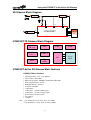
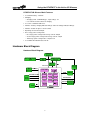
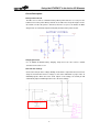
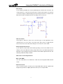
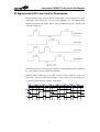
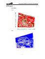
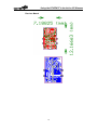
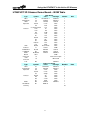
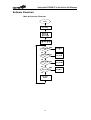
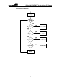
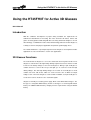
Using the HT45FH3T in the Active 3D Glasses
Using the HT45FH3T for Active 3D Glasses
D/N: HA0315E
Introduction
With the continuous development of people’s living standards, the requirements for
audio-visual entertainment is increasing, thus more and more 3D videos, movies and
games are being produced and along with this is the rising demand for 3D glasses. A new
3D technology, a combination of active shutter 3D technology and active shutter 3D glasses,
is widely used in TV and projector applications and provides good imaging effects.
The Holtek HT45FH3T is especially designed for active 3D glasses development and this
application sets out to show how it is used in such applications.
3D Glasses Functions
The main function of 3D glasses is to receive and decode the IR signals from the TV for
3D glasses control. Due to the high voltage driving requirement, a boost circuit is needed
to increase the battery voltage to 10V~12V for 3D glasses driving. A pair of 3D glasses
contains two lenses each for the left eye and right eye. As each lens needs two high
driving voltages, thus four high driving voltages are needed. So each 3D glasses circuit
contains four level shift circuits, which are used to increase the 3V MCU I/O output
voltage to 10V~12V for the 3D glasses on/off control. In addition, each pair of 3D glasses
needs an IR receiver circuit to receive external IR signals.
3D glasses normally use a battery power supply, which can be divided into two types. The
first type is a chargeable lithium battery and the second type is a non-chargeable button
battery. An additional lithium battery charging circuit is required when using the lithium
battery.
1
Using the HT45FH3T in the Active 3D Glasses
3D Glasses Block Diagram
5V
Charger IC
USB I/P
Booster
10~12V
+
ANx
PWM
VCC1
V12
TP0_1
AX
HT45FH3T
IR Receiver
BX
CX
LCD Panel
x2
DX
HT45FH3T 3D Glasses Block Diagram
Flash ROM
2K x 16
ADC
RAM
128 x 8
CTM x 2
PTM
LDO
PTM
I/O
Level
Shift
HIRC
4MHz
HT45FH3T Active 3D Glasses Main Features
HT45FH3T Basic Features
•
•
•
•
•
•
•
•
•
•
•
•
Note:
Operating Voltage : 2.2V ~ 5.5V @4MHz
System Clock : HIRC 4MHz
Multi-mode operation : NORMAL, SLOW, IDLE and SLEEP
Flash Program Memory : 2K×16
RAM Data Memory : 128 bytes
4-channel 12-bit ADC
10-bit CTM×2
10-bit PTM×1 -- provides PWM outputs
16-bit PTM×1 -- decodes IR input signals
Over Voltage Protection function
Level shift×4
3V LDO×1
1. The HT45FH3T system clock can be up to 4MHz.
2. The HT45FH3T-1 system clock can be up to 8MHz.
2
Using the HT45FH3T in the Active 3D Glasses
HT45FH3T 3D Glasses Main Features
• Uses lithium battery : 100mAh
• Charging
− Charging stand : USB Mini-B type ; input voltage : 5V
− Use 100mA constant current for charging
•
•
•
•
•
Use 3-Line controlled LCD lenses
Provides a battery charging indicator LED (Y) and a low voltage indicator LED (R)
Provides a button for glasses on/off control
Operating current: about 680µA
Three-stage power saving mode
− First stage power saving mode average current: 280µA
− Second stage power saving mode average current: 180µA
− Third stage power saving mode: self-power off
• Use nVIDIA 3D VISION Protocol for IR
Hardware Block Diagram
Hardware Block Diagram
3
Using the HT45FH3T in the Active 3D Glasses
Hardware Block Diagram Functional Description
• Main control IC : HT45FH3T-1 -- system clock : 8MHz
• Main USB charging port
•
•
•
•
•
•
•
•
•
•
This port can be connected to a computer USB interface or an external power adapter
for lithium battery charging.
Charging IC
Use 100mA constant current for lithium battery charging, during which the yellow LED
lights up.
Inductor
Used to boost the battery voltage to the LCD lenses switch voltage.
N-MOS
Used for inductor booster control.
Lithium battery
A lithium battery with a capacity of 100mAh.
Battery control circuit
Used for the third stage power saving mode: self-power off.
Button
For user manual power on/off.
LED indicator
Used for low voltage indicating.
Resistance divider
Used for booster feedback control.
IR receiver
Receives the IR signals and converts them into digital signals.
LCD lenses
Works along with the IR signal for left and right lens on/off control.
Hardware Circuit and Description
Main Board Circuit
4
Using the HT45FH3T in the Active 3D Glasses
IR Receiver Circuit
The schematic is shown below:
15pF
VDD
3M
200k
-
OPA
+
15pF
-
4.7nF
OPA
+
2k
7.15k
2k
Amplify and filter the
tiny current generated
by the IR Photodiode
CMP
+
Two signals input to the
CMP - a digital signal is
output to the MCU
5
330pF
TO MCU
Filter the amplified signal
with a negative half cycle
and add a base level
Using the HT45FH3T in the Active 3D Glasses
Circuit Description
Battery Control Circuit
The MCU can use PA1 to control the battery. When powered off, the user can press the
button to turn on the power. When powered on, the MCU must keep PA1 high to ensure
Q3 remains on. After the power is turned on, when the user press the button, the MCU
will generate an external interrupt via INT1(PA6) and turn off the power via PA1.
Charging IC Circuit
Use an IN4054 for lithium battery charging. Setup R13 to be 10K so that a 100mA
constant current can be used.
OVP Function Settings
Connect the OVP pin to the voltage dividing circuit which is output from the boost circuit.
Setup the internal D/A reference voltage to come from VDD. Write a proper value to
OVOREF[5:0] bits. When the boost circuit outputs a low voltage, the OUTH pin will
automatically output a PWM signal to increase the boost voltage.
6
Using the HT45FH3T in the Active 3D Glasses
Boost Circuit
Use the BOOST_ON (MCU Pin 8, OUTH) PWM signal to control the Q1 on/off state. The
energy stored in L1 is transferred and stored in C1 and C2, which together can generate
a 10V boost voltage. A divided voltage generated using R6 and R7 is fed back to the
MCU OVP function to maintain the boost out voltage at the correct level.
LCD Lens Control
The 3D glasses LCD lenses have 3-Line and 4-Line types. In this application, 3-Line
controlled lenses are used. For the level shift circuits, whose power is supplied by the
boost circuit, increase the LCD control voltage to 10V for the lens on/off control.
Battery Voltage Detect Circuit
Use the ADC to check the MCU internal band gap voltage, and select the ADC reference
voltage to come from VDD. If the battery voltage falls below 3V, the VDD voltage will also
fall below 3V. The band gap value detected at this moment will be higher than before, this
indicating a VDD low voltage condition.
LED used as a Low Voltage Indicator
Main control MCU
The main control MCU is the HT45FH3T-1, which has both integrated PWM and OVP
circuits.
IR Receiver Circuit
In this circuit, tiny signals received by the IR photodiode will be filtered, amplified and
integrated to generate the digital signals that can be processed by the MCU.
7
Using the HT45FH3T in the Active 3D Glasses
IR Signals and LCD Lens Control Description
Different 3D videos may generate different control signals, some IR signals have carrier
signals while some signals are carrier-free. This application uses an nVIDIA protocol
working together with IR signals with no carrier to implement decode operation and
control the LCD lenses.
Note that LCD lenses must be properly controlled to avoid the liquid crystals remaining at
the same voltage level for too long to avoid damage.
Basically, during a COM cycle, the positive level time and the negative level time are
same for the same lens. This demo board uses 3-Line control mode, the liquid crystal
level control and left/right lens control is shown below.
8
Using the HT45FH3T in the Active 3D Glasses
PCB Layout
Main Board
Front
Back
9
Using the HT45FH3T in the Active 3D Glasses
Receiver Board
10
Using the HT45FH3T in the Active 3D Glasses
HT45FH3T 3D Glasses Demo Board – BOM Table
Type
MCU
Charging IC
LDO
Capacitor
Resistor
LED
Inductor
N-MOSFET
P-MOSFE
Diode
Button
Connector
USB
connector
TVS
Main Board
Symbol
Value
Package
Number
U1
HT45FH3T-1
SSOP16
1
U2
IN4054
SOT23-5
1
U3
HT7830
SOT89
1
C9,C8
0.1uF
0603
2
C6
10uF
0805
1
C1,C2,C3,C4,C5
1uF
0603
5
R12
1K
0603
1
R14
1M
0603
1
R6
3.3M
0603
1
R13
10K
0603
1
R1
100
0603
1
R4,R2
100K
0603
2
R3
NC
0603
1
R7
360K
0603
1
R9,R10
470
0603
2
R11
470K
0603
1
D4,D5
Red, Yellow
0603
2
L1
100uH
SMD
1
Q1,Q2
AO3400
SOT23
2
Q3
AO3401
SOT23
1
D1,D2,D3
BAT54
SOD232
3
SW1
SMD
1
J5
FPC-0.5mm-10pin
1
J6
MINI USB
1
D3
SOD323
IR Receiver Board
1
Type
Symbol
Value
Package
Number
OPA
Comparator
Capacitor
U1
U2
C4
C5,C6
C3
R4,R2
R6
R5
R1
D2
D1
OPA2348
LM7239
4.7nF
0.1uF
330pF
2K
3M
7.15K
200K
BAT54
BPW 34
SOT23-8
SOT23-5
0402
0402
0402
0402
0402
0402
0402
SOD523
1
1
1
2
1
2
1
1
1
1
1
50
Resistor
Diode
Photodiode
summary
11
Note
Note
Using the HT45FH3T in the Active 3D Glasses
Software Flowchart
Main Architecture Flowchart
12
Using the HT45FH3T in the Active 3D Glasses
LCD Lenses Flowchart
13
Using the HT45FH3T in the Active 3D Glasses
Demo Board Pictures
Conclusions
As the demand for 3D glasses products is increasing, the HT45FH3T can be used to
reduce additional circuit requirements and PCB area, thus reducing production costs.
14