1
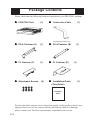
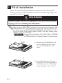
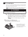
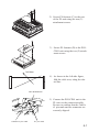
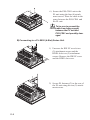
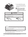
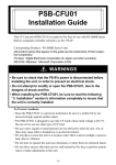
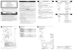
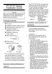
PSS-CD01
Installation Guide
Preface
The PSS-CD01 (CD-ROM Drive Unit) is designed for use with Pro-face's Compact Panel Computer PS-3701A(EdenTM ESP6000 - 667MHz Model), hereafter
referred to as the "PS-A" and for use with PL-X920 Series units, hereafter
referred to as the "PL". While the PSS-CD01 provides a convenient way to
install software into PS-A/PL unit hard disks, it is not designed to be used outside of the development environment.
Corresponding Products: PS-3701A (EdenTM ESP6000 - 667MHz Model) unit /
PL-X920 Series unit
Pro-face is a trademark of Digital Electronics Corporation, registered in Japan and
other countries. All other trademarks/registered trademarks are the properties of their
respective owners.
!
Warning - Safety Precautions
• Be sure to check that the PS-A/PL unit’s power cord is disconnected before
installing this unit. Failure to do so may cause an electric shock.
• Do not attempt to modify or open the PSS-CD01. This may cause a fire or an
electric shock.
• Be sure to read the “2. PS-A Installation” or “3. PL Installation” section completely to ensure that the PSS-CD01 is correctly installed.
To Prevent Accidents
• Since the PSS-CD01 is a precision instrument, be sure it is neither hit by nor
pressed strongly against another object.
• Be sure water, liquids or metal particles are not allowed to enter the PSS-CD01
unit's connector. Any of these may cause either a breakdown or an electric
shock.
• Do not store or operate this unit in a location where there is direct sunlight,
excessive heat, dust or vibration.
• Do not store or operate the PSS-CD01 near chemicals, or where there are
chemical fumes.
• Do not use the PSS-CD01 in locations where corrosive gases are present.
• To prevent damage to file data, be sure to shut down the PS-A/PL unit's OS
before turning OFF the main power.
E-1
Package Contents
Please check that the following items are included in your PSS-CD01 package.
PSS-CD01 Unit
(1)
Connection Cable
PS-A Fastener (A)
(1)
PS-A Fastener (B)
PL Fastener (C)
(1)
PL Fastener (D)
Attachment Screws
(8)
Installation Guide
(1)
(1)
(1)
(1)
<This Guide>
Installation
Guide
Pro-face has taken utmost care to insure the quality of this product when it was
shipped. However, for any reason, should you find any defects or damage,
please contact your Pro-face representative immediately for service.
E-2
1
Hardware Specifications
Functional
Random Access Seek
Data Transfer Speed
Disk Speed
Inferface
Power Consumption
115ms (Ave.)
16.7MB/s (Max.)
5,136 rpm (typ)
IDE (ATAPI)*1
During Startup:
1.0A (typ)
During Random Access: 0.85A (typ)
During Wait:
0.45A (typ)
*1 The PSS-CD01's connection cable is a special-purpose cable. Other types of cables
cannot be used to connect this unit to the PS-A /PL unit.
Environmental
Ambient Temperature
Storage Temperature
Ambient Humidity
Vibration Resistance
Shock Resistance
+5 oC to +50oC
-10oC to +60oC
10%RH to 80%RH (no condensation)
(during operation) 2.9m/s2 (10Hz to 25Hz)
(not operating) 588m/s2
E-3
2
PS-A Installation
Be sure to use the following installation procedures to ensure that the PSSCD01 is correctly installed. Installation procedures will differ depending on the
type of PS-A unit you are using.
WARNING
Shock Danger! Be sure to unplug the PS-A unit from its power
supply prior to installing the PSS-CD01.
When using the PSS-CD01 with the PS-A unit, be sure to change the "IDE
Primary Master PIO" and "IDE Primary Slave PIO" settings within the System Information area "INTEGRATED PERIPHERALS" to "Mode 2". Also,
be sure to set the "IDE Primary Master UDMA" and "IDE Primary Slave
UDMA" settings to "Disabled".
Compact Panel Computer PS-3701A (EdenTM ESP6000
- 667MHz Model) User Manual, Chapter 3 System Setup.
1) Unscrew the CD-ROM Drive I/F
cover's attachment screw and remove the CD-ROM Drive I/F
cover.
2) Secure PS-A fastener (A) to the
rear of the PS-A unit using the two
(2) attachment screws. Fastening
torque should be 0.5 to 0.6N•m.
E-4
3) Secure PS-A fastener (B) to the
PSS-CD01 using the two (2) attachment screws. Fastening torque
should be 0.5 to 0.6N•m.
CD-ROM Drive I/F
Cable's #1 pin mark
4) Connect the PSS-CD01 to the PS-A
unit via the connection cable. Be
sure to that the Cable's #1 pin mark
and the connector are correctly
aligned.
#1 pin mark
5) Secure the PSS-CD01 to the PS-A
unit using the four (4) attachment
screws. Fastening torque should be
0.5 to 0.6N•m. Place the cable in
the space between the PSS-CD01
and the PS-A unit.
To be sure to prevent the
cable from being caught
between the PS-A unit and
PSS-CD01 and possibly damaged.
!
CAUTION
Confirm that the connection cable is securely attached to both connectors.
Be sure to check both connectors before turning the PS-A ON.
E-5
3
PL Installation
Be sure to use the following installation procedures to ensure that the PSSCD01 unit is correctly installed. Installation procedures will differ depending on the type of PL unit you are using.
When the PSS-CD01 unit is used, the Slave HDD cannot be
used. Be sure to uninstall (remove) the Slave HDD unit.
WARNING
Shock Danger! Be sure to unplug the PL unit from its power supply
prior to installing the PSS-CD01 unit.
When using the CD-ROM drive unit with the PL-X920 Series unit, be
sure to change the "IDE Primary Master PIO" and "IDE Primary Slave
PIO" settings within the "System Information area | INTEGRATED
PERIPHERALS" to "Mode 2". Also, be sure to set the "IDE Primary
Master UDMA" and "IDE Primary Slave UDMA" settings to "Disabled".
PL Series User Manual, Chapter 5 System Setup.
Connecting to a PL-X920 Series Unit
A) Connecting to a PL-X920 (2-Slot) Series Unit
1) Unscrew the IDE I/F cover's two
(2) attachment screws and the
HDD1 slot's two (2) attachment
screws. Remove the IDE I/F cover
and the HDD1 slot cover.
E-6
2) Secure PL fastener (C) to the rear
of the PL unit using the two (2)
attachment screws.
3) Secure PL fastener (D) to the PSSCD01 unit using the two (2) attachment screws.
fold here
4) As shown in the left-side figure,
fold the cable over, along the dotted line.
IDE INTERFACE
5) Connect the PSS-CD01 unit to the
PL unit via the connection cable.
Be sure to confirm that the Cable's
#1 pin mark and the connector are
correctly aligned.
Cable's #1 pin mark
#1 pin mark
E-7
6) Secure the PSS-CD01 unit to the
PL unit using the four (4) attachment screws. Place the cable in the
space between the PSS-CD01 and
the PL unit.
To be sure to prevent the
cable from being caught
between the PL unit and
PSS-CD01 and possibly damaged.
B) Connecting to a PL-X920 (4-Slot) Series Unit
1) Unscrew the IDE I/F cover's two
(2) attachment screws and the
HDD1 slot's two (2) attachment
screws. Remove the IDE I/F cover
and the HDD1 slot cover.
2) Secure PL fastener (C) to the rear of
the PL unit using the two (2) attachment screws.
E-8
3) Secure PL fastener (D) to the PSSCD01 unit using the two (2) attachment screws.
fold here
4) As shown in the left-side figure,
fold the cable over, along the dotted line.
IDE INTERFACE
5) Connect the PSS-CD01 unit to the
PL unit via the connection cable.
Be sure to confirm that the Cable's
#1 pin mark and the connector are
correctly aligned.
Cable's #1 pin mark
#1 pin mark
E-9
6) Secure the PSS-CD01 unit to the
PL unit using the four (4) attachment screws. Place the cable in the
space between the PSS-CD01 and
the PL unit.
To be sure to prevent the
cable from being caught
between the PL unit and
PSS-CD01 and possibly damaged.
!
CAUTION
Refer to the following drawings to confirm that the connection cable
is securely attached to both connectors. Be sure to check both connectors
before turning the PL ON, since incorrect attachment of the connectors
can cause equipment damage.
X
X
Note
Please be aware that Digital Electronics Corporation shall not be held
liable by the user for any damages, losses, or third party claims arising
from the uses of this product.
Digital Electronics Corporation
8-2-52 Nanko Higashi, Suminoe-ku, Osaka 559-0031, Japan
URL: http://www.pro-face.com/
© 2004 Digital Electronics Corporation All rights reserved.
E-10