Transcript
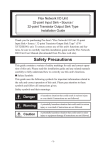
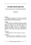
This guide contains a variety of safety symbols for safe and correct operation
of this unit. Please read this installation guide and any related manuals carefully to fully understand how to correctly use this unit's functions.
Safety Symbols
This guide uses the following symbols for important information related to
the safe and correct operation of this unit. Please pay attention to these symbols and follow all instructions given.
Caution
• Communication cables or I/O signal lines must be wired separately from
the main circuit (high-voltage, high-current) line, high-frequency lines such
as inverter lines, and the power cord. Otherwise, a malfunction may occur
due to noise.
• This unit must be properly installed according to directions in the Installation Guide and User Manual. Improper installation may cause the unit to
malfunction, or operate incorrectly.
• This unit must be properly wired according to directions in the Installation
Guide and User Manual. Improper wiring may cause a unit malfunction,
failure or electric shock.
• Do not allow foreign substances, including chips, wire pieces, water, or
liquids to enter inside this unit's case. Otherwise, a malfunction, failure,
electric shock, or fire may occur.
• When disposing of this unit, it should be disposed of according to your
country’s industrial waste disposal laws.
A hazardous situation that will result in death or major
Danger equipment damage if instructions are not followed.
A potentially hazardous situation that could result in death
Warning or major equipment damage if instructions are not followed.
A potentially hazardous situation that could result in minor
Caution injury or equipment damage if instructions are not followed.
Specifications
3
Electrical (Control Section)
Rated Voltage
DC24V
Input Voltage
DC20.4 to DC28.8V
Allowable Voltage Drop
Up to 10ms (power supply: DC24V)
In-Rush Current
30A or less
Power Consumption
4.8W or less
AC1500V 10mA 1minute (between input/output and FG terminals)
AC500V 1minute (between power supply 1st level and 2nd level)
10M Ω or more at DC500V
(between charging and FG terminals)
Voltage Endurance
Insulation Resistance
(via noise simulator)
Flex Network 4 Channel
Analog/Digital Conversion Unit
(FN-AD04AH11)
• Whenever installing, dismantling, wiring, and conducting maintenance or
inspections, be sure to disconnect power to this unit to prevent the possibility of electric shock or fire.
• Do not disassemble or modify this unit, since it may lead to an electric
shock or fire.
• Do not use this unit in an environment that contains flammable gases since
it may cause an explosion.
• Do not use this unit in an environment with conditions outside of the ranges
specified in this Installation Guide and in the User Manual. Otherwise, an
electric shock, fire, malfunction or other failure may occur.
• Because of the possibility of an electric shock or malfunction, do not touch
the power terminals while the unit is operating.
Safety Precautions
4-Channel Analog Unit Wiring
The driver for the Flex Network Unit is required in order to use the unit.
For GLC2000 Series and LT Series,
You can select the Flex Network Driver via GP-PRO/PBIII C-Package (ProControl Editor) or LT Editor.
If the selection of the appropriate unit's name does not appear in the [I/O
Configuration] - [I/O Unit Settings] area, you will need to update the driver
file.
You can download the latest driver from Pro-face's Home Page.
For GP3000 Series,
You can select the Flex Network Driver via GP-Pro EX as an I/O driver.
Also, you can download the driver and the Flex Network Analog Unit User
Manual from Pro-face's web site. (http://www.pro-face.com/)
4
Installation
Removal
Installation
Use a screwdriver to push the attachment hook down and release
the unit. Then, pull the unit forward and off the rail.
Hook the analog unit's top face
groove over the top edge of the DIN
rail. Next, push the bottom of the I/
O unit forward until the attachment
hook clicks into place on the DIN
rail.
Rating
IP30
Input
Input Range
Input Range Switch
Calibration Function
Accuracy
Insulation Method
Processing (after conversion)
Conversion Timing
12 bit
4ch (fixed)
up to 2 milliseconds
0 to 5V (Impedance 1M Ω)
1 to 5V (Impedance 1M Ω)
0 to 10V (Impedance 1M Ω)
-5 to 5V (Impedance 1M Ω)
-10 to 10V (Impedance 1M Ω)
0 to 20mA (Impedance 200Ω)
4 to 20mA (Impedance 200Ω)
Depends on rotary switch settings
Offset, Gain setting
Setting the upper limit value /
lower limit value for each range via switch
0.3% / FS (25°C)
0.5% / FS (0°C to 55°C)
Photocoupler Insulation
(input terminals / between internal circuits)
Simple Average, Running Average
Exclude Max. / Min. values
Simultaneous - all channels (not selectable)
Ch 1 output voltage terminals ...................................................... V1+, AG1, FG
Ch 1 output current terminals ....................................................... I1+, AG1, FG
Shield
V+
Lowpass
Filter
AG
FG
Analog
S/W
OP
Amplifier
A/D
Converter
Shield
I+
Lowpass
Filter
AG
FG
Analog
S/W
OP
Amplifier
A/D
Converter
Analog
GND
• The analog unit's power supply should be separated
from the sensor's power supply to prevent the unit from
being affected by external noise.
• Use Two FG terminals with 4 channels, and use one FG
terminal with 2 channels.
50 [1.97]
Values
Values
Values
Values
158.0+1.5
(6.22+0.06)
5
Range SW Setting
0
1
2
3
4
5
6
7 to F
Setting
Setting
Setting
Setting
*1 : The factory setting is “0”.
Range
0V ~ 5V (*1)
1V ~ 5V
0V ~ 10V
-5V ~ 5V
-10V ~ 10V
0 ~ 20mA
4 ~ 20mAV
Disabled
*1 : The factory setting is “0 (0 to 5V)”.
Switch Settings
Examples of S-No. (station no.) settings
SW1 ......... Reserved
SW2 ......... 6 - 6 Mbps,
12 - 12 Mbps
SW3, 4 ..... UP - ON (1)
Down - OFF (0)
Dip Switch
SW3
SW4
S-No. (Station no.)
Switch
OFF(0)
ON(1)
0
ON(1)
ON(1)
F
S-No.
10h(16)
Arrow tip .... Setting values
(0 to F)
3Fh(63)
The Flex Network interface and the analog unit, or all distributed analog
units, are connected using a cross wiring system. (T-type systems cannot be
used.)
Pro-face suggests the following communication cables.
Distributor
Pro-face
Order Code
FN-CABLE2010-31-MS
FN-CABLE2050-31-MS
FN-CABLE2200-31-MS
Length
10m
50m
200m
3.8[0.15]
or less
Power Cable
(Unit: mm [in.])
5.2[0.20]
or longer
φ3.2[φ0.13]
or larger
• Cable diameter can be up to 1.25 mm2. Be sure to twist all wire ends before
attaching crimp terminals.
• Use the same type crimp terminals as used for the communication cable.
Analog Input Cable
2-M4
200Ω
Current
Input
Unit
Calibration
CH1- AD Lower / Upper Limit
CH2- AD Lower / Upper Limit
CH3- AD Lower / Upper Limit
CH4- AD Lower / Upper Limit
Disabled (*1)
Shield wire (SLD)
158.0+1.5
(6.22+0.06)
(Unit: mm [in.])
Analog
GND
Current Input
Table 2
Select SW Setting
1
2
3
4
0, 5 to F
White (TR-)
Create installation screw holes for installing the unit using the dimensions
given below. Secure the analog unit in place with M4 size screws. Screw
torque should be 1.0 to 1.3 N•m.
1MΩ
Voltage
Input
Unit
Bottom View
A: Dip Switches .......................... Set communication speeds and S-No. (first digit).
B: S-No. (station no.) Switch ...... Sets S-No. (last digit).
C: Terminator .............................. Switches termination ON/OFF. Turns ON the units at both ends
of the communication cable.
D: Status LED ............................. Indicates the unit's current operation status.
E: Calibration Select Switch ........ Selects a calibration setting. Refer to “Table 1”.
F: Calibration Perform Switch ..... Pushing this switch performs calibration of the AD input’s lower
limit value (MIN), upper limit value (MAX).
G: Range Switch ......................... Switches a range setting. Refer to “Table 2”.
H: DIN Rail Attachment Hook .... is used to attach the unit to a DIN rail
Blue (TR+)
Installing the unit in a Panel
Voltage Input
Factory (Default) settings :
Communication speed: 6 Mbps
S-No. (station no.): 0
Be sure that the top and bottom faces of the unit are facing the
correct direction and the unit is installed in a vertical position.
Incorrect installation may prevent heat from dissipating.
Input Circuit Drawing
Resolution
Number of Input Channel
Conversion Time
Push down
41.0+0.3
[1.61+0.01]
30% RH to 95% RH (non-condensation) level RH-1
Flat-head screwdriver
Digital/Analog
conversion unit
Current
Output
Device
Side View
When preparing the cable wire ends:
- Cover shielded wires with shield tape or with an insulation tube.
- Use insulated crimp terminal.
- If you use a pressure connection terminal without insulation, cover it with a
shield tape or an insulation tube. Cover uninsulated crimp termials with shield
tape or a tube-type insulation.
DIN rail
0°C to 55°C
-25°C to +70°C
Front View
Communication Cable
Installing the unit on a 35 mm DIN Rail:
The left drawing explains
the connection using ch1
and ch3 as – row. Each
channel can be used
connecting to voltage
input units, or current
input units.
Voltage
Output
Device
H G
C A B D F E
OFF .... Termination OFF
ON ...... Termination ON
Environmental
Ambient Operating
Temperature
Ambient Storage
Temperature
Ambient Humidity
(Unit: mm [in.])
168 [6.61]
Table 1
This section explains the Flex Network 4 Channel Analog/Digital Conversion Unit Connection and Circuit Drawings.
DC24V
Flex Network 4 Channel
Analog/Digital Conversion Unit
Installation Guide (this guide)
Driver & Manual
41.0+0.3
[1.61+0.01]
2
Package Contents
Warning
This section shows the external dimensions of the analog/digital conversion
unit, part names and part settings.
6.0[0.24]
or less
Thank you for purchasing Pro-face's "Flex Network 4 Channel Analog/
Digital Conversion Unit" (FN-AD04AH11). To ensure correct use of this
unit's functions and features, be sure to carefully read both this Installation
Guide and the Flex Network Analog Unit User Manual. Flex Network 4
Channel Analog/Digital Conversion Unit" (FN-AD04AH11) is not CE
marked, UL/c-UL (CSA) listed products.
External Dimensions / Part Names
50 [1.97]
• An emergency stop circuit and an interlock circuit should be constructed
outside of this unit. Constructing these circuits inside this unit may cause a
runaway situation, system failure, or an accident due to unit failure.
• Systems using this unit should be designed so that output signals which
could cause a serious accident are monitored from outside the unit.
• This unit is designed to be a general-purpose device for general industries, and is neither designed nor produced to be used with equipment or
systems in potentially life-threatening conditions. If you are considering
using this unit for special uses, including nuclear power control devices,
electric power devices, aerospace equipment, medical life support equipment, or transportation vehicles, please contact your local Flex Network
distributor.
Flex Network 4 Channel
Analog/Digital Conversion Unit
Installation Guide
1
To Prevent Unit Damage
• Do not store or operate this unit in either direct sunlight or excessively
dusty or dirty environments.
• Since this unit is a precision instrument, do not store or use it in locations
where excessive shocks or vibration may occur.
• Do not block this unit's ventilation holes, or operate it in an environment
that may cause it to overheat.
• Do not operate this unit in locations where sudden temperature changes
can cause condensation to form inside the unit.
• Do not use paint thinner or organic solvents to clean this unit.
6 [0.24]
Danger
Wiring
This section describes both the cables and crimp terminals used for wiring each
type of cable. The terminal screw torque should be 0.6 to 1.0 N•m.
• Cable diameter can be up to 0.9 mm2.
(CPEV-S φ up to 0.9mm - 2 core, shielded)
• Use the same type crimp terminals as used for the communication cable.
Confirm that all I/O unit terminal screws are securely
tightened, even they are not used.
Note
Please be aware that Digital Electronics Corporation shall not be held liable by the user for any damages,
losses,or third party claims arising
from the uses of this product.
Digital Electronics Corporation
8-2-52 Nanko-higashi
Suminoe-ku, Osaka 559-0031 JAPAN
Tel: +81-(0)6-6613-1101
Fax: +81-(0)6-6613-5888
URL: http://www.proface.co.jp/
©Copyright 2000 Digital Electronics Corporation. All rights reserved.