1
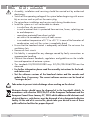
Professional Analogue Digital HD Encoder KLASSE PADE 4001 English CLASS GSS Grundig SAT Systems GmbH Beuthener Strasse 43 D-90471 Nuremberg Phone: Fax: E-mail: Internet: +49 (0) 911 / 703 8877 +49 (0) 911 / 703 9210 [email protected] http://www.gss.de/en Contents 1 Safety regulations and notes......................................................................... 3 2 General information..................................................................................... 4 2.1 Packing contents.............................................................................4 2.2 Meaning of the symbols used...........................................................4 2.3 Technical data................................................................................4 2.4 Description....................................................................................6 Signal runtime................................................................................6 Software versions...........................................................................7 Block diagram................................................................................7 3 Assembly..................................................................................................... 8 3.1 Installing the cassette......................................................................8 3.2 EMC regulations.............................................................................9 3.3 Cassette overview........................................................................10 3.4 Connecting the cassette.................................................................10 4 The control panel at a glance...................................................................... 11 4.1 Menu items..................................................................................11 4.2 Control panel...............................................................................11 5 Programming............................................................................................. 12 5.1 Programming procedure................................................................12 5.2 Programming the cassette..............................................................14 Selecting the cassette....................................................................14 Encoder......................................................................................15 Service ID (SID).......................................................................15 Programme name....................................................................15 Total data rate.........................................................................16 Video signal type/input............................................................16 Group of Picture – GoP............................................................17 Audio input / Audio level.........................................................17 Audio data rate.......................................................................18 ASI output....................................................................................18 ASI transfer rate......................................................................19 ASI options.............................................................................19 ASI Input station filter....................................................................20 Output data rate...........................................................................22 Transport stream ID and ORGNET ID..............................................23 Network Information Table (NIT).....................................................23 Factory reset / Soft reset...............................................................24 Factory reset...........................................................................24 Soft reset................................................................................25 Saving settings ............................................................................25 6 Final procedures......................................................................................... 26 - 2 - PADE 4001 1 Safety regulations and notes • Assembly, installation and servicing should be carried out by authorised electricians. • Switch off the operating voltage of the system before beginning with assembly or service work or pull out the mains plug. • Do not perform installation and service work during thunderstorms. • Install the system so it will not be able to vibrate… - in a dust-free, dry environment - in such a manner that it is protected from moisture, fumes, splashing water and dampness - somewhere protected from direct sunlight - not within the immediate vicinity of heat sources - in an ambient temperature of 0 °C to +50 °C. In case of the formation of condensation wait until the system is completely dried. • Ensure that the head-end station is adequately ventilated. Do not cover the ventilation slots. • Beware of short circuits • No liability is accepted for any damage caused by faulty connections or inappropriate handling. • Observe the relevant standards, regulations and guidelines on the installation and operation of antenna systems. • The standards EN/DIN EN 50083 resp. IEC/EN/DIN EN 60728 must be observed. • For further information please read the assembly instructions for the headend station used. • Test the software versions of the head-end station and the cassette and update them if necessary. The current software versions can be found at "www.gss.de/en". Take action to prevent static discharge when working on the device! Electronic devices should never be disposed of in the household rubbish. In accordance with directive 2002/96/EC of the European Parliament and the European Council from January 27, 2003 which addresses old electronic and electrical devices, such devices must be disposed of at a designated collection facility. At the end of its service life, please take your device to one of these public collection facilities for proper disposal. - 3 - PADE 4001 2 General 2.1 Pac k i n g contents 1 Cassette PADE 4001 1 BNC cable 1 Brief assembly instructions 2.2 M e a n i n g 1 Measuring log o f t h e s ym b o l s u s e d Important note —> General note • Performing works 2.3 T e c h n i c a l information data The devices meet the following EU directives: 73/23/EWG, 89/336/EWG The product fulfils the guidelines and standards for CE labelling (page 27). Unless otherwise noted all values are specified as "typical". Component Video Input Input level...............................................................Y 1 Vss, Pb/Pr 0,7 Vpp Input impedance.............................................................................. 75 Ω Tested Video Formats.......... 1920x1080i50, 1280x720p50, 720x576p50, 720x480p59 Supported standards...........................................................................PAL CVBS Video Input Input level....................................................................................... 1 Vpp Input impedance.............................................................................. 75 Ω Frequency range............................................................ 20 Hz … 5 MHz Supported standards..................................................................... PAL BG Audio Input Input level................................................................................500 mVrms Frequency range............................................................20 Hz … 15 kHz - 4 - PADE 4001 MPEG4 Encoder Transport stream.....................................H.264/AVC High Profile Level 4.0 Setting range of total data rate (video + audio + tables)............ 1 Mbit/s…30 Mbit/s Video data rate: 1920x1080i............................................................ 6 Mbit/s…24 Mbit/s 1280x720p............................................................. 4 Mbit/s…24 Mbit/s 720x576i................................................................ 1 Mbit/s…10 Mbit/s 720x480i................................................................ 2 Mbit/s…10 Mbit/s Audio data rate.......................................................... 32 kb/s…384 kb/s ASI Interfaces Norm............................................................................DIN EN 50083-9 Format................................................................MPEG ISO IEC 13818-1 Max. data rate....................................................................... 108 Mbit/s Impedance...................................................................................... 75 Ω Level (input / output).......................................................800 mVpp ± 10% Return loss (input)................................................> 17 dB (5 … 270 MHz) Connections Video Inputs: Component YPbPr............................................................. 3 Cinch sockets CVBS................................................................................1 Cinch socket Audio Inputs: S/PDIF (PCM)..........................................................................1 TOSLINK Analogous Stereo ............................................................ 2 Cinch sockets ASI input...................................................................1 BNC socket, 75 Ω ASI output..................................................................1 BNC socket, 75 Ω Connection strip (10-pin):.........................................for supply voltages and control circuit RS-232 socket:........................................................ serial update interface Remote maintenance Remotely controllable (via PSW 1000*):............................................... yes Remote update (via BEflash*):.............................................................. yes (* and a corresponding management unit) - 5 - PADE 4001 2.4 D e s c r i p t i o n The MPEG4 Encoder Cassette converts a HD or SD video and audio signal into a MPEG4 data stream (transport stream) and outputs it via the ASI interface. For the Video input it can be selected between YPbPr (SD/HD) or CVBS (SD). All common HDTV formats up to a resolution of 1920 × 1080i @ 50/60Hz are supported. The stereo audio signal of a YPbPr resp. CVBS signal can be fed in via the cinch sockets (analogous) or the TOSLINK S/PDIF interface (PCM). A status LED at the ASI input indicates, whether a input signal is present (green). The MPEG4 encoder generates a transport stream according to H.264/AVC (Advanced Video Coding) High Profile Level 4.0 standard. The transport stream can be cascaded via ASI. ASI The cassette is designed for use in head-end stations of the profi line. The operating software of the cassette can be updated via the 9-pin D-SUB socket "RS-232" using a PC or notebook and the software "BE-Flash". You can find the current operating software on the website "www.gss.de/en". Signal Channel switching at a HD source, becomes effective only after a time delay (of up to 3 seconds) because of the signal runtime! runtime - 6 - PADE 4001 S o f t wa r e Cassette After activating the cassette the software version of the cassette is displayed (see page 14). Control unit To operate these cassettes the software version of the control unit must be "V44" or higher. Approximately 5 minutes after the last keypress the software version of the control unit is displayed. If necessary, you can activate the indication of the software version of the control unit manually: • Press any two keys on the control unit of the head-end station simultaneously until the display goes dark and the software version, e.g. "V 44" appears. B lo c k v e rs i o n s d i ag r a m ASI-Eingang ASI input BNC PCM R Audio Audio ENCODER L Y/FBAS Y/CVBS FBAS/CVBS TPS µP / TPS-MODUL SPDIF TPS ASI-Ausgang ASI output BNC Video Pb Pr Component - 7 - PADE 4001 3 Assembly 3.1 I n s ta l l i n g the cassette – Ensure the head-end station is mounted so it will not be able to vibrate. Avoid, for example, mounting the head-end station onto a lift shaft or any other wall or floor construction that vibrates in a similar way. – Before installing or changing a cassette unplug the power cable from the mains power socket. • Remove the fastening screws 1 of an unoccupied slot from the bracket of the head-end station. • Insert the cassette in this slot and push it into the housing. • Align the cassette and apply slight pressure to connect it to the connections of the board and the HF bus bar. • Fasten the cassette with the screws 1. 1 1 - 8 - PADE 4001 3.2 EMC KLASSE CLASS r e g u l at i o n s To comply with the current EMC regulations, it is necessary to connect the lines leading in and out of the head-end station using cable terminals. When mounting the cassette in a head-end station which is installed in a 19" cabinet, make sure the connections leading in and out for the 19" cabinet are made using cable terminals. The attenuation of shielding of the connection lines for ASI and antenna must meet the requirements for "Class A". • Insert the required number of cable terminals in the openings provided in the head-end station or in the 19" cabinet. Tighten the nuts on the cable terminals until the teeth on the lock washer have penetrated the exterior coating and a good connection is made between the housing and cable terminals. - 9 - PADE 4001 3.3 C a s s e t t e ov e rv i e w 1 2 3 4 5 6 1 2 3 4 5 6 7 8 9 0 D-SUB socket "RS 232" ASI output ASI input Status LED ASI input OPTICAL S/PDIF PCM audio input TOSLINK Audio input R analogous Audio input L analogous Video input Y/CVBS Video input Pb Video input Pr 7 8 9 10 The operating software of the cassette can be updated via the 9-pin D-SUB socket "RS 232" using a PC or notebook and the software "BE-Flash". You can find the current operating software on the website "www.gss.de/en". 3.4 C o n n e c t i n g • Dependent on the input signal connect the source device via cable terminals to the input sockets "Y/Pb/Pr" 8/9/0 or "CVBS" 8, "Audio R" 6, "Audio L" 7 or "OPTICAL" 5. • If necessary connect the ASI input 3 and the ASI output 2 to the peripheral devices. • Connect the head-end station to the mains. the cassette - 10 - PADE 4001 4 The control panel at a glance 4.1 M e n u items Program the cassette using the buttons on the control unit of the head-end station. The two-line display of the control unit then shows the menus. Use the key to select the following main menu items: – – – – – – – – 4.2 C o n t r o l V44 PROFESSIONAL pa n e l The key pad on the head-end station is used to scroll through the menus: scrolls forward through the menus. scrolls backward through the menus. select parameters in the menus selects sub-menus BE-Remote Cassette Encoder ASI Output ASI Input Data rate TS/ONID NIT Factory reset set values,. saves all entries. - 11 - PADE 4001 5 Programming 5.1 Progr a mming Ein/On BE–Remote procedure V 44 please wait … Bedienhinweise "blättert" Menüs vorwärts. "blättert" Menüs rückwärts. wählen die Eingabeposition wählt Untermenü stellen Werte ein,. speichert alle Eingaben. 1 zeigt die Eingabeposition t > 10 s Bx 1 ……… ……… ……… A (Page 13) Bx 2 ENCODER Bx 3 ……… V5 HD ……… ……… ––– (Page 13) B > 2 sec. = abbrechen / cancel Bx 2 HD ENCODER => Bx 2 Operating Hints scrolls forward through the menu. scrolls backward through the menu. select the enter position. selects a submenu. set values and triggers actions. saves all entries. 1 shows the enter position SERVICE-ID 00001 Bx 2 NAME löschen / delete HD BITRATE 2.0 … 30.0 Mbps Off Audio only VIDEO-IN yPbPr CVBS Bx 2 10.0 Mbps Bx 2 yPbPr Bx 2 VIDEO-GOP IBBP Bx 2 AUDIO-IN CINCH Bx 2 ASI OUTPUT => 0 dB Bx 2 AUDIO 192 kbps Stereo Bx 2 IBBP IPPP IBP CINCH OPTICAL ASI RATE 108000 KBits - 12 - Bx 2 ASI OPTION PADE 4001 Bx 2 OUTPUT ASI ASI RATE Bx 2 => 108000 KBits ASI OPTION Bx 2 cont. 188 pos. Bx 2 INPUT Bx 2 ASI OK => all /204 /neg. /burst FILTER all manual nur bei Einstellung "manual" Only with setting "manual" BX 2 TV + Services entfernen / hinzufügen Removing / activating services 01/04 Das Erste Bx 2 ! nächster Service (Programm) next service (station) DATARATE 93.0/ 108.0 Mb TS/ONID Bx 2 0x0001,0100 Bx 4A/B off NIT => Make ▶ Make (Page 12) A on / off Bx 4 Defaults FACTORY => ▶ Bx 4 FACTORY STORE Bx 4 RESET RESET => M => M - 13 - auf Werkseinstellung zurücksetzen und speichern M reset to factory defaults and store (Page 12) A M (Page 12) B PADE 4001 5.2 P r o g r a m m i n g the cassette —> Pressing the button for longer than 2 seconds cancels the programming procedure. This takes you back to the programme item "Selecting the cassette" from any menu. Any entries that have not been saved are reset to the previous settings. —> Entries in the menus can be saved by pressing the key. You are taken back to the "Selecting the cassette" menu item. —> The parameters and functions to be set are underlined (Cursor). • Switch on the head-end station. —> The display shows the software version (e.g. V 44) —> The processor reads the cassettes‘ data (approximately 10 seconds). Ein/On BE–Remote V 44 please wait ... t > 10 s Selecting the cassette Bx 1 ……… ……… ……… Bx 2 ENCODER Bx 3 ……… V5 HD ……… ……… ––– • If necessary select the cassette to be programmed by repeatedly pressing the button (e.g. Box 2). —> • Press the The display shows e.g. the menu "Bx 2 ENCODER": "Bx 2" stands for slot 2 "ENCODER HD" type of cassette "V 5" software version of the cassette button. —> The "Encoder settings" – "ENCODER" main menu is activated. - 14 - PADE 4001 Encoder Via this menu you get access to the submenus in order to do the encoder settings and to select the desired input. —> If no encoder settings should be done, press button . The "ASI output" – "OUTPUT" main menu is activated (page 18). • Press button . —> The "SERVICE-ID" submenu is activated. S e rv i c e ID (SID) In this menu you can assign a Service ID for the signal which is to be encoded. Bx 2 SERVICE-ID 00001 • Use the buttons to select the digit of the SID to be set and use buttons to set the desired SID. —> Take care, not to assign the same SID twice. • Press the button. —> The "Programme name" – "NAME" submenu is activated. Progr a mme In this menu, a programme name for the signal which is to be encoded, can be set. name Bx 2 NAME HD • Use the use buttons to select the digit of the channel name to be set and buttons to set the desired character . —> Press button to delete the complete name. - 15 - PADE 4001 • Press the button. —> The "Total data rate" – "BITRATE" submenu is activated. T ota l In this menu you set the total data rate (video + audio + tables), with which the input signal shall be encoded. data r at e Bx 2 BITRATE 10.0 Mbps —> The higher the resolution of the input video signal, the higher the data rate must be set: 1920x1080i 6,3 Mbit/s…24 Mbit/s 1280x720p 4,3 Mbit/s…24 Mbit/s 720x576i 1,3 Mbit/s…10 Mbit/s 720x480i 2,3 Mbit/s…10 Mbit/s • Use the buttons to set the data rate of the video signal (1.0…30.0 Mbit/sec). If only audio signals are to be encoded, set the data rate to "Audio only". In setting "Off" the encoder is switched off. • Press the button. —> The "Video signal type/input" – "INPUT" submenu is activated. Vi d e o s i g n a l t y p e /i n p u t In this menu you select whether you would like to feed in a Composite video signal "YPbPr" via the green/blue/red cinch sockets or a CVBS video signal "CVBS" via the green cinch socket. Bx 2 VIDEO-IN yPbPr • Use the • Press the buttons to select the desired type of video signal / input. button. —> The "Group of Picture" – "VIDEO-GOP" submenu is activated. - 16 - PADE 4001 Group The GoP describes the order of reference and difference pictures of the data stream. This influences the compression. of P i c t u r e – G o P Bx 2 VIDEO-GOP IBBP • Use the buttons to select the desired "Group of Picture" (GoP). —> IBBP – high compression – HDTV at low data rate for "normal picture contents" at higher channel switching delay. IBP – medium compression – HDTV at medium data rate for "fast moving contents" (e.g. sport) at medium channel switching delay. IPPP - minor compression – HDTV at high data rate for "fast conversion" at short channel switching delay. • Press the button. —> The "Audio input/Audio level" – "AUDIO-IN" submenu is activated. Audio Herein you can select the audio input, via which the corresponding sound signal shall be fed. input / A u d i o level Bx 2 AUDIO-IN CINCH 0 dB —> An analogous audio signal can be fed via the cinch sockets and a digital PCM audio signal can be fed via the "Toslink" socket (optical S/PDIF interface). Audio input: • Use the buttons to select the desired audio input. Audio level: • Press button • Use the , to get to the level setting. buttons to enter the desired audio level (-11dB…+11dB). - 17 - PADE 4001 • Press the button. —> The "Audio data rate" – "AUDIO" submenu is activated. Audio In this menu you set the data rate with which the audio signal shall be encoded. data r at e • Use the Bx 2 AUDIO 192 kbps Stereo buttons to enter the desired audio data rate. —> Some data rates are selectable for mono as well as stereo signals. • Press the button. —> Return to the main menu "Encoder settings". • Press the button. —> The "ASI output" – "OUTPUT ASI" main menu is activated. ASI o u t p u t Herein you get access to the submenus for ASI output settings. —> If no ASI output settings should be done, press button The "ASI Input station filter" – "INPUT" main menu is activated. . Bx 2 OUTPUT ASI • Press the => button. —> The "ASI transfer rate" – "ASI RATE" submenu is activated. - 18 - PADE 4001 ASI t r a n s f e r In this menu you set the transfer rate for the ASI component connected (incl. stuffing - filled up user data rate). For this setting please take the required information from the documentation (technical data) of the ASI component to be connected. r at e Bx 2 ASI RATE 108000 KBits • Use the use the • Press the buttons to select the digits to be set for the transfer rate then buttons to set the transfer rate wished. button. —> The "ASI options" – "ASI OPTION" submenu is activated. ASI o p t i o n s In this menu you define the size of the data packets, their polarity and the type of transmission. For this setting please take the required information from the documentation (technical data) of the ASI component to be connected. Bx 2 188 pos. ASI OPTION cont. • Press the bits). buttons to set the size of the data packets ("188" or "204" • If the polarity of the data to be transmitted has to be changed, press the to select "pos." (positive – standard) and using the buttons set to "neg." (negative). • To change the type of transmission press the buttons to select "cont." (continuous – standard) and using the buttons set to "burst". —> Setting "cont." The data packets of the user data are spaced out evenly in the transport stream. - 19 - PADE 4001 —> Setting "burst" The data packets of the user data are collected to a great data packet in the transport stream. • Press the button. —> Return to the main menu "ASI output" • Press the button. —> The "ASI Input station filter" – "INPUT" main menu is activated. ASI I n p u t Herein you get access to the submenus for ASI input filter settings. s tat i o n f i lt e r —> If no ASI input filter settings should be done, press button . The "Output data rate" – "DATARATE" main menu is activated (page 22) Bx 2 INPUT ASI OK => —> If no ASI input signal is present, "– –" is displayed instead of "OK". • Press the Bx 2 INPUT ASI – – => button. Bx 2 FILTER all Using buttons you can select, whether all services (all) or only selected services (manual) are passed through. • Activate the filter function by selecting "manual". • Press the button. - 20 - PADE 4001 —> All services from the ASI input will be read, and then displayed with name and type of the service.. —> If no service is found, the following message will appear in the display: "no Service". In this case, check previously adjusted settings for the cassette and the components connected to the ASI input. —> The display shows e.g.: Bx 2 TV + 01/04 Das Erste Meaning of the indicators in the example: "TV" "Television" (type of service) " + " The currently selected service is passed through "01/04" The 1st of 4 services is being displayed. "Das Erste" Name of the service Further possible terms displayed: "ASI" ASI station filter "RA" "Radio" (type of service) For radio stations, the background of the screen of the connected TV or test receiver is darkened. "–" The currently selected service is blocked. " * " The star means that the service selected is scrambled. —> If a service number (e.g. "131") appears instead of "TV" or "RA", this indicates that an unnamed service or an undefined transport stream is being received. • Use the buttons to call up the services in sequential order, then use buttons to pass through (indicated by " + ") or to block them (" – "). —> If the filter function is activated (setting "manual"), only services which are marked by "+" will be passed. If the services at the ASI input are changed, new services (which are not marked by "+") will be blocked. —> Pressing the button all services can be passed through or blocked. • Press the button. —> Return to the main menu "ASI input station filter" - 21 - PADE 4001 • Press the button. —> The "Output data rate" – "DATARATE" menu is activated. Output Herein the current needed and the maximum data rate is displayed. data r at e Bx 2 DATARATE 93.0/ 108.0 Mb —> The maximum data rate is dependent on the settings of the ASI data rate. If the current needed data rate is higher than the maximum possible data rate, a "!" is indicated. Bx 2 ! DATARATE 112.0/ 108.0 Mb —> The value 108.0Mb results from the ASI RATE setting. In this case correct the corresponding settings. • Press the button. —> The "Transport stream ID and ORGNET ID" – "TS/ONID" menu is activated. - 22 - PADE 4001 Tr a n s p o r t s t r e a m ID a n d ORGNET ID If the input signals are encoded to a separate transport stream (if no transport stream with ORGNET-ID is present at the ASI input), a new ORGNET-ID must be assigned to the transport stream. Bx 2 TS/ONID 0x0001,0100 • Use the and use the buttons to select the digit of the hexadecimal number to be set buttons to set the desired character. —> The combination of TS and ON ID must be unique at the plant. —> If the TS/ONID was changed a new NIT must be generated. • Press the button. —> The " Network Information Table" – "NIT" menu is activated. N e t wo r k I n f o r m at i o n Ta b l e (NIT) Bx 2 off • Use the • Press the NIT => Make buttons to switch off or on the NIT. button to activate NIT "Make". —> All active cassettes which are able to output a NIT ("NIT cassettes") must be set and ready for reception. —> The NITs of all "NIT cassettes" are switched on. —> The cassette fetches all the information (output frequencies, output data rates, etc.) it needs from all the "NIT cassettes" in order to generate the NIT. This process may take a few seconds. Then the NIT is generated, added and sent to all "NIT cassettes". The other "NIT cassettes" also add this new NIT. The status of all "NIT cassettes" in the NIT menu changes to "on". The display shows: "read … / copy …". - 23 - PADE 4001 • To switch off the new NIT ("off") press the button. —> The NITs of the other "NIT cassettes" will stay switched on. When the NIT of the cassette is switched on again ("on") by pressing the button, the previously generated NIT is added again. If you have changed parameters in the meantime, you must first select "Make" to generate a new, up-to-date NIT. • Press the button. —> The "Factory reset" – "FACTORY Defaults" main menu is activated. Fac to ry Via this menu you get access to the submenus to reset all settings to the factory defaults or to perform a soft reset (cassette restart). reset / S o f t Bx 2 r es e t FACTORY Defaults Bx 2 ▶ => FACTORY STORE Bx 2 RESET RESET Fac to ry • Press the => M => M M M reset button. —> The "Factory Store" submenu is activated. Bx 2 FACTORY STORE => M • In order to perform a factory reset press the - 24 - button. PADE 4001 —> The cassette is reset to factory defaults. The display shows "STORE" —> Back to "Selecting the cassette" (page 14). • In order to perform a soft reset (cassette restart) or to return to the main menu "Factory Default" press the button. —> The "Reset" submenu is activated. Soft In this submenu you can perform a soft reset (cassette restart). reset Bx 2 RESET RESET => M • In order to perform a soft reset (cassette restart) press the button —> The cassette is restarted. —> By pressing the button, you will be returned to the main menu "Encoder" without saving the factory defaults (page 15). S av i n g • Press the s e t t i n gs button. —> Return to "Selecting the cassette" (page 14). —> The settings are saved. - 25 - PADE 4001 6 Final procedures After installing the head-end station, upgrading accessories or installing cassettes it is necessary to tighten all cable connections, cable terminals and cover screws in order to maintain compliance with current EMC regulations securely. • Securely tighten the cable bolted connections using an appropriate openended spanner. • Mount the front cover (see assembly instructions of the head-end station). - 26 - PADE 4001 Declaration of CE conformity - 27 - PADE 4001 Service: Phone: +49 (0) 911 / 703 2221 • Fax: +49 (0) 911 / 703 2326 • Email: [email protected] Grundig SAT Systems GmbH • Beuthener Straße 43 • D-90471 Nürnberg Alterations reserved. Technical data E. & O.E. © by GSS GmbH V5/27112013