1
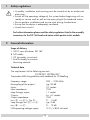
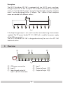
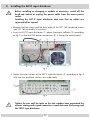
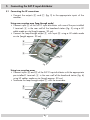
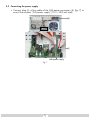
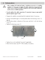
STC 160 Head-End Station
SAT IF input distributor
SID 162
Notes on the Assembly Instructions.
As well as this supplementary Assembly Instructions, the Assembly Instructions for the STC 160
apply.
English
Assembly Instructions
Grundig SAT SystEms
GSS
Grundig SAT Systems GmbH
Beuthener Strasse 43
D-90471 Nuremberg
Phone:
Fax:
Email:
Internet:
+49 (0) 911 / 703 8877
+49 (0) 911 / 703 9210
[email protected]
www.gss.tv
Contents
1 Safety regulations................................................................................................ 3
2 General information............................................................................................. 3
Scope of delivery................................................................................... 3
Technical data........................................................................................ 3
Description............................................................................................ 4
3 Overview............................................................................................................. 4
4 Installing the SAT IF input distributor...................................................................... 5
5 Connecting the SAT IF input distributor................................................................... 6
5.1 Connecting the HF connections................................................................ 6
5.2 Connecting the power supply................................................................... 7
6 Final procedures................................................................................................... 8
-2-
1
Safety regulations
• Assembly, installation and servicing must be carried out by an authorised
electrician.
•Switch off the operating voltage of the system before beginning with assembly or service work or pull out the mains plug of the head-end station.
•Do not perform installation and service work during thunderstorms.
•Ensure that the device is adequately ventilated.
•Avoid short circuits!
For further information please read the safety regulations listed in the assembly
instructions for the STC 160 head-end station which pertain to this module.
2
General information
Scope of delivery
1 SAT IF input distributor SID 162
8 SAT cables
1 CD (assembly instructions)
1 Brief Assembly Instructions
Mounting material
Technical data
The requirements of the following are met:
73/23/EEC, 89/336/EEC
The product fulfils the guidelines and standards for CE labelling.
Frequency range:
Decoupling of the outputs:
Inputs: Input impedance:
Loop through output:
Outputs:
Output impedance:
Loss D —> E (s. Fig. 2):
Loop through loss D —> C:
Loss B —> F:
LNB operating voltage supply:
950 … 2150 MHz
typ. 20 dB
2 F sockets
75 Ω
1 F socket
6 + 4 F sockets
75 Ω
9 … 14 dB
typ. 5 dB
9 … 12 dB
12 V / ≤ 800 mA total
-3-
Description
The SAT IF distributor SID 162 is equipped with two SAT IF inputs, one loopthrough output and 10 SAT IF outputs. This enables to distribute two reception
areas to 4 and 6 SAT IF outputs. Using the loop-through output the reception
area 1 can be distributed to the 10 outputs. The F sockets of both reception
areas are marked with different colours.
Fig. 1
If the loop-through output is not used it must be terminated using the terminator
supplied. The DC power feed of 12 V / ≤ 800 mA is used for the power supply
of the LNBs connected.
The SAT IF distributor SID 162 is designed exclusively for use in the STC 160
head-end station.
3
Overview
!
#
"
Fig. 2
A LNB power connection
B Input 2
C Loop-through output of input 1 D with terminator
D
E
F
-4-
Input 1
Outputs of input 1
Outputs of input 2
D
B
4
Installing the SAT IF input distributor
Before installing or changing a module or accessory, switch off the
head-end station or unplug the power cable from the mains power
socket.
Installing the SAT IF input distributor take care that no cables are
squeezed off or injured.
• Remove the front cover and the base plate of the STC 160 head-end station
(see STC 160 assembly instructions).
• Insert the SAT IF input distributor 1 above the output collector 2 according
to fig. 3 so that the LNB power connection A is facing the control panel.
Fig. 3
• Fasten the outer sockets of the SAT IF input distributor
with two nuts and lock washers put under each.
3 according to fig. 4
Fig. 4
Tighten the nuts until the teeth on the lock washers have penetrated the
exterior coating and a good connection is made between the housing and
the SAT IF input distributor.
-5-
5
Connecting the SAT IF input distributor
5.1 Connecting the HF connections
• Connect the outputs
modules.
E
and
F
(fig. 2) to the appropriate inputs of the
Using one reception area (loop-through mode)
• Connect input D of the SAT IF input distributor with one of the pre-installed
F terminals 4 in the rear wall of the head-end station (fig. 5) using a HF
cable made on-site (length approx. 30 cm).
• Connect the loop-through output C with input B using a HF cable made
on-site (length approx. 30 cm).
!
Fig. 5
Using two reception areas
• Connect inputs B and D of the SAT IF input distributor with the appropriate
pre-installed F terminals 4 in the rear wall of the head-end station (fig. 6)
using HF cables made on-site (length approx. 30 cm).
• Terminate the loop-through output C with the terminator.
!
Fig. 6
-6-
5.2 Connecting the power supply
• Connect plug 6 of the cable of the LNB power connection A (fig. 7) to
one of the contacts “LNB power supply” (12 V / 800 mA total).
LNB power supply
Fig. 7
-7-
6
Final procedures
After installing the head-end station, retrofitting accessories or installing
modules it is necessary to tighten all cable connections, F terminals and
cover screws in order to maintain compliance with current EMC regulations
and to ensure a reliable operation.
• Securely tighten the cable connections (F connector) using an open-ended
spanner (spanner gap 11 mm).
• Program the modules connected and the head-end station if necessary.
• Position the breakthroughs in the base plate above the fastening screws 2
(fig. 8).
• Push the base plate in direction of the arrow and lock it with the locking
screw 1.
• Tighten the fastening screws 2.
Fig. 8
• Tighten the nuts of retrofitted F terminals if applicable.
• Mount the front cover (see STC 160 assembly instructions).
Alterations reserved. Technical data E. & O.E.
© by GSS GmbH
08012008