1
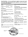
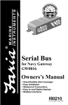
Fuel Manager
Fuel Management System
IMPORTANT
A®
FARI
CORP. UN
CAS
VIL
L
E,
C
T
READ THE COMPLETE USER’S MANUAL BEFORE INSTALLING AND
OPERATING YOUR NEW FUEL MANAGER.
M
E
AD
U
IN
.S.A
07C
. DLP0
FUEL
MANAGER
FLOW
TOTAL
• Displays Fuel Flow in
GPH or LPH
• Total or Trip Fuel Used
• Low Fuel Alarm
• Calculates Fuel
Remaining In Tank
• Gas Engines Only
IS0324 rev D ecr 8569 08/2011
Issue Date
Description
1/26/11
Rev A ecr 8415 01/2011
2/08/11
Rev A1 ecr 8415 02/2011
3/11/11
Rev A2 ecr 8451 03/2011
05/10/11
Rev B ecr 8513 05/2011
06/08/11
Rev C ecr 8528 06/2011
08/18/11
Rev D ecr 8569
Contents
Specifications . . . . . . . . . . . . . . . . . . . . . . . . . . . . . . . . . . . . . . . 1
Installation
Location . . . . . . . . . . . . . . . . . . . . . . . . . . . . . . . . . . . . . . . . .
Mounting . . . . . . . . . . . . . . . . . . . . . . . . . . . . . . . . . . . . . . . .
Wiring Connection . . . . . . . . . . . . . . . . . . . . . . . . . . . . . . . . .
Installation of the Fuel Flow Transducer . . . . . . . . . . . . . . . .
2
2
3
4
Description . . . . . . . . . . . . . . . . . . . . . . . . . . . . . . . . . . . . . . . . . 5
Instrument Setup
Select units of measure . . . . . . . . . . . . . . . . . . . . . . . . . . . . .
Calibration . . . . . . . . . . . . . . . . . . . . . . . . . . . . . . . . . . . . . . .
Flow Averaging . . . . . . . . . . . . . . . . . . . . . . . . . . . . . . . . . . .
Fuel Flow Menu . . . . . . . . . . . . . . . . . . . . . . . . . . . . . . . . . . .
5
5
7
7
Operation
Fuel Flow . . . . . . . . . . . . . . . . . . . . . . . . . . . . . . . . . . . . . . .
Fuel Remaining Functions . . . . . . . . . . . . . . . . . . . . . . . . . . .
Trip Log . . . . . . . . . . . . . . . . . . . . . . . . . . . . . . . . . . . . . .
Total Log . . . . . . . . . . . . . . . . . . . . . . . . . . . . . . . . . . . . .
Reset Trip and Total Logs . . . . . . . . . . . . . . . . . . . . .
Low Fuel Alarm . . . . . . . . . . . . . . . . . . . . . . . . . . . . . . . .
Setting Low Fuel Alarm . . . . . . . . . . . . . . . . . . . . . .
Fuel Remaining (Gas) . . . . . . . . . . . . . . . . . . . . . . . . . . .
Changing the Fuel Remaining value . . . . . . . . . . . . .
Things you should know . . . . . . . . . . . . . . . . . . . . . . . . . . . .
8
8
8
8
8
9
9
10
10
11
Troubleshooting Chart
No Display . . . . . . . . . . . . . . . . . . . . . . . . . . . . . . . . . . . . . . .
No Flow Reading indicated . . . . . . . . . . . . . . . . . . . . . . . . . .
Low Flow Reading indicated . . . . . . . . . . . . . . . . . . . . . . . . .
No Fuel Reading . . . . . . . . . . . . . . . . . . . . . . . . . . . . . . . . . .
High or Erratic reading . . . . . . . . . . . . . . . . . . . . . . . . . . . . .
12
12
12
12
12
Specifications - for use with gas engines only and it will
not work with recirculating fuel systems such as Diesels
and certain EFI Motors.
Size
Mount
Both Trip Log and Total Log can be
reset.
21/16” diameter hole
Depth behind face plate
Display 3” min.
Multi character LCD
Backlighting
White colored diffused back lighting.
Water Integrity
Front will withstand direct water spray.
Alarm
Audio and visual alarm indicates
remaining fuel total has dropped below
a preset alarm value.
Fuel Remaining
User enters a fuel value into memory.
The quantity of fuel used is automatically
subtracted from the total.
This value remains in memory at power
down.
Operating Voltage
8 VDC to 16.5 VDC
Operating Temperature
0ºC to 50ºC (32ºF to 122ºF)
Current Drain
90 mA maximum
transducer.
Flow
0.5 to 34 US gallons per hour
2 to 129 liters per hour
0.4 to 28 imperial gallons per hour
The instrument may show erratic
readings or indicate 0 flow below .5 GPH
due to the differences in manufacturer’s
fuel management systems. However,
the total fuel consumed shown will be
accurate.
Logs
Logs record fuel used up to 999 display
units.
with
Compliance/Certifications
<6 dB quieting on any marine radio
channel (with 3 dB gain antenna) within
one meter of the instrument.
Complies with CE EMC standards
EN50081-1 and EN50082-1 and FCC
Section 15.
Complies with International Standard
ISO 8846:1990(E).
A®
FARI
Backlit for Night
Operation
CORP. UN
CAS
VIL
L
E,
C
T
Both Trip Log and Total Log are saved
in memory at power down.
M
E
AD
U
IN
.S.A
07C
. DLP0
Changes Value Up
FUEL
MANAGER
FLOW
TOTAL
Changes Value Down
1
supplied
IMPORTANT
READ THE COMPLETE USER’S MANUAL BEFORE INSTALLING AND
OPERATING YOUR NEW FUEL MANAGER.
WARNING
Always install the Fuel Flow Transducer AFTER the primary filter. The primary filter must
be a good quality water separator type with a minimum filtration of 30 microns or better.
(A 10 or 2 micron filter is preferred. The lower the micron rating the finer the filtration.)
Failure to provide this level of filtration protection will result in inaccurate readings or total
failure or damage to the transducer.
If there is not a suitable length of hose after the primary filter, an in-line filter (30 micron
or better) should be fitted before the Fuel Flow transducer. Damage due to insufficient
filtration is not covered by warranty. If in doubt please consult your local Marine dealer for
advice prior to installation.
Installation
Always wire your Fuel Manager into your boat’s ignition so that when the engine
is turned on, the gauge is recording the fuel used. If an accessory switch is used
and you forget to turn the unit on then the gauge will not have recorded the fuel
used and will be inaccurate. If you are unsure how to do this, contact a qualified
marine electrician.
Mounting
Location
The Fuel Manager is designed for
above or below deck installation.
• The instrument panel may be up to
3/4” in thickness.
Select a position that is:
• Drill a 2 1/16” hole in the instrument
panel.
• On a flat surface
• Remove brackets and insert the
instrument so the back is flush with
the instrument panel.
• At least 12” from a compass
• At least 20” from any radio
• Easy to read by the helmsman and
crew
• Protection from physical damage
• Accessible to electrical cable
connections.
• Slide the back clamp over the
instrument and tighten mounting
nuts until secure. Six inch pounds of
torque is only required.
Instrument Panel
2 1/16" Hole
Mounting Hardware
Mounting Bracket
Instrument
2
IMPORTANT
READ THE COMPLETE USER’S MANUAL BEFORE INSTALLING AND
OPERATING YOUR NEW FUEL MANAGER.
Wiring Connection
• Keep electrical and transducer cables away from alternator or other noise
generating electrical cables. Avoid connecting the instrument to power
circuits that share loads with ignition, alternators, inverters and radio
transmitters.
• Electrical power supply connections should always be as short as possible.
• Connect the red wire from the gauge to the ignition switch (DC Positive
Voltage), through a 1 amp fuse (not included).
• Connect the green wire from the gauge to the electrical ground.
• Connect the fuel flow transducer to the gauge as follows:
Fuel Manager
(Connector [3])
(Ignition)
Green
Shield
White
White
Red
Black
-
+
(Battery)
3
Positive
Red
Green
White
DC Input Voltage
Ground
Transducer Signal
Sender
Ground
1 amp fuse
(not included)
Fuel Manager
Black
Shield
White
DC Input Voltage
Ground
Transducer Signal
Fuel Flow
Transducer
WARNING
Every effort has been made by the manufacturer to ensure that the materials used in the
Fuel Flow transducer will operate reliably with different fuel mixtures. The manufacturer
or its distributors can not be held responsible for how the formulation of the fuel may
affect the performance and durability of the transducer, as in many countries the petrolchemical companies are free to change the contents of the fuel.
This transducer has been specially developed for use in Marine application with gasoline
inboard and outboard engines only. The manufacturer does not warrant its operation of
suitability for any other application.
Installation of the Fuel Flow Transducer
The fuel flow transducer is designed for installation in a Coast Guard approved
3/8” (9.5 mm) flexible fuel line. The transducer MUST be installed AFTER the main
fuel filter.
It should be located well away from any area where it will be effected by excessive
heat or vibration from the engine. It is preferable to mount the transducer in a
vertical position (as shown below).
If your boat does not have a flexible fuel hose and is fitted with a metal fuel line or
fuel line other than the US Coast Guard 3.8” (9.5 mm) a section of 3/8” (9.5 mm)
must be fitted between the fuel transducer and the existing fuel lines. Consult an
Engine Specialist for professional advice to ensure the various fuel line connection
are correctly made.
Always ensure that the hose on either side of the transducer is clamped to the
hull or similar rigid structure, to minimize vibration. Mounting hardware is NOT
supplied.
After selecting a suitable location, cut the fuel line and using the fuel hose attaching
clips provided install the transducer so that the FUEL IN side of the transducer
connects to the fuel tank.
UP
to
Fuel
Manager
Shield
White
Black
Fuel Flow
Engine
Clamp to Hull
(or simular rigid
structure)
Fuel Flow
Transducer
Transducer
must sit above the
maximum fuel
level.
Filter
Tank
3/8” (9.5 MM)
4
Description
The Fuel Manager is a device that
shows the amount of fuel used by
measuring the amount of fuel passed
through a transducer and averages
that flow to give an estimate of the fuel
used while operating your boat. You
can learn more about this averaging on
page 7.
2. Once the unit is on, release the down
button. The current display setting is
shown, as pictured below:
The Fuel Manager is designed for ease
of use. There are two buttons.
Imperial Gallons
US Gallons
Liters
Pressing the up button will show you the
Rate of Flow through the transducer.
Pressing the down button allows the
user to select the functions concerning
the Fuel Remaining in the tank.
3. To select another display setting, use
the up or down button to change the
value.
OR
4. To save the change and exit this
mode, press and hold both the up
and down buttons together for one
(1) second.
Instrument Setup
Select units of measure
The Fuel Manager can display fuel
values in US gallons, Liters or Imperial
gallons. To change the current display
setting, perform the following steps.
1. While holding the down button, power
up the unit by turning on the ignition
key.
5
The fuel values are now displayed using
the new setting.
Calibration
The fuel transducer supplied with the
Fuel Manager, when installed properly,
will provide readings at better than
5% accuracy. Individual calibration will
increase this level of accuracy to better
than 2% over a fuel flow range of 2 to
32 US gallons per hour (10 to 120 Liters
per hour).
While a properly calibrated unit should
provide accuracy within the published
limits, it is recommended the user
should also have a level sender or fuel
level gauge installed in the boat.
This is necessary due to possible
operator induced errors such as
forgetting to reset the fuel used when
filling the tank, or other operator
controlled actions that may render the
device inaccurate.
Perform the following steps to calibrate
your Fuel Manager.
1. Reset the total log value to zero (see
page 8)
2. Set the Fuel Remaining value to the
size of your tank. (See page 10)
If no action is performed within twenty
(20) seconds the unit will return to the
normal operating mode.
7. Calibrate. Use the up or down button
to change the display and indicate
the actual volume of fuel used.
OR
Once calibration is completed.
8. Press both the up and down buttons
together and hold for two (2) seconds
to save the value.
3. Fill the tank. Go boating.
Note: The larger the amount the more
accurate the calibration will be. The
recommended minimum volume is 10
gallons or at least 1/4 of the total tank
volume, if smaller than 40 gallons.
4. Refill the tank. Take note of the
actual volume of fuel used to fill the
tank and the fuel used indicated by
the total log. If these two totals are
different, the instrument may require
calibration.
5. While holding the up button, power
up the unit by turning on the ignition
key.
9) Shut the ignition off to power down
the Fuel Manager.
10. Set your desired AVG setting. (See
page 7, follow steps 1 thru 5.)
6. Release the button. The display
flashes the current total log value.
6
Flow Averaging
This function sets the period over
which the fuel flow is averaged. The
period can be set in the range of 1 to
99 seconds.
Description
Normally engines do not draw fuel from
the tank at a constant rate. Instead, they
draw fuel at a high rate for a short time
until the carburetor bowl or injection
reservoir is full, and then draw no fuel
for a few seconds. If the true flow rate
were displayed, it would be too erratic
to read.
Usually a value of 10-15 seconds will
give satisfactory results for two stroke
naturally carburetor engines. Four
stroke engines that use an electronic
fuel injection may require longer
periods. If the reading seems erratic
you can increase the period.
A large number means the fuel flow
display will have a slow response time
but more accurate average readings,
and a short period means the display
will have a quick response time and
erratic display readings.
The flow period setting only affects
the fuel flow display. It does not
affect the fuel used or fuel remaining
measurement in terms of accuracy.
Flow Average menu
Enter the flow averaging menu:
1. While holding the up button, power
up the unit by turning on the ignition
key.
2. Press and hold both the up and
down buttons together for two (2)
7
seconds to enter fuel flow average
mode.
3. The fuel flow average period
menu, AVG is displayed briefly and
the default value of 10 seconds is
displayed if you have not previously
changed it.
4. Use the up or down button to select
a new value between 1 and 99
seconds.
OR
5. Press and hold both the up and
down buttons together for one (1)
second to save the new averaging
period and return to Normal mode.
Operation
Fuel Flow
Press the up button to display the
current fuel flow rate.
Fuel Remaining Functions
Resetting the TRIP or TOTAL Log
To reset a log, press the down button
until the display indicates the name of
the log to be reset.
Press and hold both the up and down
buttons together for two (2) seconds.
Press the down button to cycle through
the functions of the Fuel Manager.
The display will flash while pressing the
buttons.
Trip Log
The Trip Log display shows the amount
of fuel used on a trip or since the last
time the log was reset by the operator.
Release the buttons and the log will
reset to zero (0).
Total Log
The Total display shows the total
amount of fuel used since last reset.
The Trip log value may be reset without
changing the Total log value. If the Total
log is reset to zero (0), then the Trip log
will automatically reset to zero (0).
8
Note: If the Total log exceeds 999 then
both it and the Trip log will be reset to
zero (0).
Low Fuel Alarm
The Low Fuel Alarm displays desired
remaining volume of fuel which will
trigger an alarm. The number indicates
the number of units based on your
settings.
Press and hold both up and down
buttons together for two (2) seconds.
The displayed value will begin to flash.
If the fuel remaining value drops below
the fuel alarm value, the alarm will
sound and the “ALRM” will flash.
Use the up or down button to change
the value of the alarm.
Press any button to mute the alarm.
The “ALRM” will continue to flash as
long as the alarm condition remains.
OR
If no setting has been set, or the user
has entered zero (0), then the display
will show “OFF”.
A value of zero (0) will turn off the alarm.
Set the Low Fuel Alarm
To change the value of the Low Fuel
Alarm press the down button until the
display shows the “ALRM” display.
9
Press and hold the up and down buttons
together for three (3) seconds to save
the new value and exit the function.
Gas
The Gas display shows the amount of
fuel remaining in the tank.
Press and hold the up and down buttons
together for three (3) seconds to save
the new value and exit the function.
Changing the fuel remaining value
To change the value of fuel remaining in
the tank press the down button until the
display shows the “GAS” display.
Press and hold both up and down
buttons together for two (2) seconds.
The displayed value will begin to flash.
Use the up or down button to change
the value.
OR
10
Things you should know.
A) It is possible for erratic fuel flow readings at low RPM values due to the fuel
reservoir filling and emptying, this is normal and expected.
B) It is possible for very low fuel flow readings, often even 0.0 GPH, at idle due to
the low fuel consumption of the engine.
C) It is possible for up to 0.5 GPH fluctuations in fuel flow readings at low RPM
due to the fuel consumption of the engine. A recommendation would be to
increase the fuel flow averaging TIME by following the instructions on page
#8.
11
Troubleshooting Chart
No display:
1) Check DC power connections and DC polarity with voltmeter.
2) Check the fuse.
No flow reading indicated:
1) Check connection to flow transducer
2) Remove the transducer from the fuel line, and perform a no pressure flush with
the residual fuel left in the transducer by covering the sensor inlet and outlet
and shaking for 20 to 30 seconds. When complete with flush, finish with a
low to medium pressure (5 PSI maximum) blow into the transducer from both
directions manually. When blowing trough the transducer a whistling noise will
indicate that the turbine is rotating.
Low flow reading indicated:
1) Check your primary and secondary filters for obstructions. If no filters are fitted
this will lead to blockage and damage of the flow transducer (see page 4).
2) Check calibration is correct.
No fuel reading:
1) Check your primary and secondary filters for obstructions. If no filters are fitted
this will lead to blockage and damage of flow transducer (see page 4).
High or erratic reading:
1) Check fuel connections are well made. Air in fuel lines will cause erratic or high
readings.
12
Copyright 2005 by the Thomas G. Faria Corporation, Uncasville, CT USA
Faria® is the trademark of the Thomas G. Faria Corporation. All rights reserved. No part of this
publication may be reproduced in any form, in an electronic retrieval system or otherwise, without the
prior written permission of the company.