1
SuperRelayManual
INNOVATIVE & SMALL
EASY TO PROGRAM
SuperRelayManual
LOST COST FACTOR
Updated: December 2008
The xLogic SuperRelay is an Easy
Electronic Co., Ltd manufactured
REPLACES MINI
PLCs
product.
Content.
Introduction
Getting started
Installation and wiring
Functions
Configuring
Applications
Software
Technical data
xLogic SuperRelay
Users Manual
Introduction
Congratulations with your xLogic SuperRelay provided by Easy Electronic
Co., Ltd.
The xLogic SuperRelay is a compact and expandable CPU replacing mini
PLCs, multiple timers, relays and counters.
The xLogic SuperRelay perfectly fits in the space between timing relays
and low-end PLCs. Each CPU incorporates not only a real-time clock and
calendar, but also provides support for optional expansion I/O modules
to enhance control and monitoring applications.
Data adjustments can easily be performed via the keypad, the LCD
display, or through the easy-to-use xLogic software. DIN-rail and panel
mounted options are both are available, offering full flexibility to the
various installation needs of your application.
The xLogic SuperRelay is available in 120V/240V AC or 12V and 24V DC
versions, making it the ideal solution for relay replacement, or simple
control applications as building and parking lot lighting, managing
automatic lighting, access control, watering systems, pump
control, ventilation systems, home automation and a wide field of other
applications demanding low cost to be a primary design issue.
We strongly recommended taking the time to read this manual, before
putting the xLogic SuperRelay to work. Installation, programming and use
of the unit are detailed in this manual. The feature-rich xLogic SuperRelay
provides a for off-line operation mode, allowing full configuration and
testing prior to in-field service commissioning. In reviewing this manual
you will discover many additional advantageous product properties, it will
greatly simplify and optimize the use of your xLogic SuperRelay.
2
User’s Manual
xLogic SuperRelay
Valid range for this manual
The manual applies to devices of the series ELC-18, ELC-12 and ELC-E
Safety Guideline
This manual contains notices you have to observe in order to ensure your
personal safety, as well as to prevent damage to property. The notices referring
to your personal safety are highlighted in the manual by a safety alert symbol,
notices referring to property damage only have no safety alert symbol. The notices
shown below are graded according to the degree of danger.
Caution
Indicates that death or severe personal injury may result if proper precautions are not
taken
Caution
With a safety alert symbol indicates that minor personal injury can result if proper
precautions are not taken.
Caution
Without a safety alert symbol indicates that property damage can result if proper
precautions are not taken.
Attention
Indicates that an unintended result or situation can occur if the corresponding notice
is not taken into account.
If more than one degree of danger is present, the warning notice
representing the highest degree of danger will be used. A notice warning of
injury to persons with a safety alert symbol may also include a warning
relating to property damage.
3
xLogic SuperRelay
Users Manual
Qualified Personnel
The device/system may only be set up and used in conjunction with this
documentation. Commissioning and operation of a device/system may only be
performed by qualified personnel. Within the context of the safety notices in this
documentation qualified persons are defined as persons who are authorized to
commission, ground and label devices, systems and circuits in accordance with
established safety practices and standards.
Prescribed Usage
Note the following:
Warning
This device and its components may only be used for the applications described
in the catalog or the technical description, and only in connection with devices
or components from other manufacturers which have been approved or
recommended by EASY. Correct, reliable operation of the product requires
proper transport, storage, positioning and assembly as well as careful operation
and maintenance.
Trademarks
All names identified by xLogic are registered trademarks of the EASY. The
remaining trademarks in this publication may be trademarks whose use by third
parties for their own purposes could violate the rights of the owner.
Copyright Easy 2007 all rights reserved
The distribution and duplication of this document or the utilization and
transmission of its contents are not permitted without express written
permission. Offenders will be liable for damages. All rights, including
rights created by patent grant or registration of a utility model or design,
are reserved.
Disclaim of Liability
We have reviewed the contents of this publication to ensure consistency with the
hardware and software described. Since variance cannot be precluded entirely, we
cannot guarantee full consistency. However, the information in this publication is reviewed regularly and any necessary corrections are included in subsequent editions.
4
User’s Manual
xLogic SuperRelay
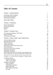
Contents
1. General Introduction to xLogic
8
2. Installation/remove xLogic
2.1 DIN rail mounting
2.2 Wiring the xLogic
2.2.1Connecting the power supply
2.2.2 Connecting xLogic inputs
2.2.3 Connecting xLogic outputs
18
19
20
20
21
24
3. Programming xLogic
3.1 General Input & Output functions
3.1.1 Inputs
3.1.2 Cursor keys
3.1.3 Outputs
3.1.4 Permanent logical levels HI and LO
3.1.5 Shift register bits
3.1.6 Analog inputs
3.2 Basic functions list – GF
3.2.1 AND
3.2.2 AND with edge evaluation
3.2.3 NAND
3.2.4 NAND with edge evaluation
3.2.5 OR
3.2.6 NOR
3.2.7 XOR
3.2.8 NOT
3.3 Basics on special functions
3.3.1 Designation of the inputs
3.3.2 Time response
3.3.3 Backup of the real-time clock
3.3.4 Retentivity
3.3.5 Parameter protection
3.3.6 Calculating the gain and offset of analog values
3.4 Special functions list – SF
3.4.1 On-delay
3.4.2 Off-delay
3.4.3 On-/Off-delay
3.4.4 Retentive on-delay
3.4.5 Wiping relay (pulse output)
3.4.6 Edge triggered wiping relay
3.4.7 Asynchronous pulse generator
3.4.8 Random generator
3.4.9 Stairway lighting switch
3.4.10 Multiple function switch
3.4.11 Weekly timer
3.4.12 Yearly timer
3.4.13 Up/down counter
26
26
26
27
27
27
27
28
29
29
31
31
32
33
34
35
35
35
36
37
38
38
39
39
41
41
43
44
46
47
48
49
50
52
53
55
57
60
5
xLogic SuperRelay
Users Manual
3.4.14 Hours counter
3.4.15 Threshold trigger
3.4.16 Latching relay
3.4.17 Pulse relay
3.4.18 Message text
3.4.19 Softkey
3.4.20 Shift register
3.4.21 Analog comparator
3.4.22 Analog threshold trigger
3.4.23 Analog amplifier
3.4.24 Analog value monitoring
3.4.25 Analog differential trigger
3.4.26 Analog multiplexer
3.5 HMI block
3.5.1 System cover
3.5.2 System input/output
62
65
67
68
69
73
74
76
78
81
82
84
86
88
88
89
4. Configuring xLogic
4.1 Instruction of xLogic-HMI
4.2 Select function page
4.2.1 Run/Stop
4.2.2 Set parameter
4.2.3 Set password
4.2.4 Set Address of expansion module
4.2.5 Modification Methods of System Time
91
91
92
94
95
99
102
103
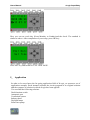
5.Application
5.1 Dual-function switch
5.1.1 Standard solution
5.1.2 The scheme of xLogic
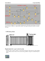
5.2 Automatic gate
5.2.1 Standard solution
5.2.2 The scheme of xLogic
5.3 Ventilation system
5.3.1 Standard solution
5.3.2 The scheme of xLogic
5.4 Factory door
5.4.1 Standard solution
5.4.2 The scheme of xLogic
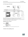
5.5 Daylight lamp system
5.5.1 Standard solution
5.5.2 The scheme of xLogic
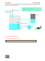
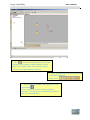
5.6 Rainwater pump
5.6.1 Standard solution
5.6.2 The scheme of xLogic
105
106
106
108
109
110
111
113
114
115
117
118
118
120
121
122
124
125
125
6
User’s Manual
xLogic SuperRelay
6.
xLogic Software
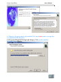
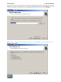
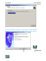
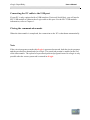
6.1 Connecting the xLogic to a PC
127
151
Appendix
A
Technical data
A.1 General technical data
A.2 Technical data: xLogic (ELC series)
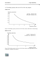
A.3 Relay switch life
153
153
155
159
7
xLogic SuperRelay
Users Manual
1. General Introduction to xLogic
Overview
xLogic SuperRelay is a universal logic module made by Easy Electronic Co., Ltd and
marketed by Inter Reps Ltd. to selected distributors around the globe.
xLogic SuperRelay is a compact and expandable CPU replacing mini PLCs,
multiple timers, relays and counters.
The xLogic SuperRelay perfectly fits in the space between timing relays and a
low-end PLCs. Each CPU incorporates not only a real-time clock and calendar, but
also provides support for optional expansion I/O modules to enhance control and
monitoring applications.
Data adjustments can easily be performed via the keypad, the LCD display,
or through the easy-to-use xLogic software. DIN-rail and panel mounted options
are both are available, offering full flexibility to the various installation needs
of your application.
The xLogic SuperRelay is available in 120V/240V AC or 12V and 24V DC versions,
making it the ideal solution for relay replacement, or simple control applications as
building and parking lot lighting, managing automatic lighting, access control,
watering systems, pump control, ventilation systems, home automation and a
wide field of other applications demanding low cost to be a primary design issue.
Highlight features:
8
4-lines, 10-character per line, backlight display.
Multiple value display and input via keypad and LCD display.
Function Block Diagram
Standard Modbus RTU communication protocol supported.
CAN BUS protocol based expansion modules
Expandable up to 31 linked modules reaching fast reacting 514 I/O points
RS232 and RS485 port (expandable port of CPU unit).
Long distance remote I/O
Optional Ethernet connectivity
SMS Alarm / Alert module
SuperRelay accepts SMS programming
SSI encoder interface module
Supplies 8 analogue inputs with DC0-10V.
Real Time Clock (RTC)
Two channel high-speed counting (99Khz)
Pre-configured standard functions, e.g. on/ off-delays, pulse relay and
softkey
User’s Manual
xLogic SuperRelay
2 PWM channels
RS232 communication download cable with photo-electricity isolation
USB communication download cable with photo-electricity isolation
Programmable capability up to 256 function blocks(ELC-18)
Mounting via modular 35mm DIN rail or screw fixed mounting plate
On-line monitor capability
Compact design
Low cost pricing
Some of the things xLogic can do for you?
The xLogic SuperRelay provides solutions for commercial, industrial, building and
domestic applications such as lighting, pumping, ventilation, shutter operations or
in switching cabinets. The application field is widespread and these are just a few
to mention.
Using the CAN bus and Ethernet connectivity allows the user to realize various
extensive (real-time) monitoring and control applications. Utilizing the optional
SMS module the systems can furthermore be remotely controlled via (GSM) cell
phone. SMS Alarms, status updates and any other desirable messages can be
provided at set triggers.
Special versions without operator panel and display unit are available for series
production applications in small machine, installation and cabinet building
environments to further slash cost.
9
xLogic SuperRelay
Users Manual
xLogic devices:
xLogic Basic is available in two voltage classes:
*Classes 1: DC12-24V: i.e.: ELC-18DC Series and ELC-12DC Series.
*Classes2:AC110-240V: i.e.: ELC-18AC Series and ELC-12AC
Series
In the versions:
* With Display: ELC-18 Series (12 inputs and 6 outputs)
* Without Display: ELC-12 Series (8 inputs and 4 outputs)
ELC-18 Series is equipped with an expansion bus (Can Bus)
Each Version is provides 36 pre-configured standard and special function blocks for the
creation of your circuit program.
Expansion modules:
* xLogic digital modules are available for operation with 12…24V DC, and 110.. .240 V AC,
and are equipped with eight inputs and eight outputs.
* xLogic analog modules are available for operation with 12…24 V DC and are
equipped with six digital and two analog inputs.
Communication modules:
xLogic:RS232 communication module (type:ELC-RS232)
It is kind of universal module with photoelectricity isolation which can be directly
connected to standard 9-pin port of PC, also kind of interface module which can
enable user’s program to be downloaded into xLogic main module through
xLogicsoft for running.
xLogic: USB communication module (type: ELC-USB).
It is kind of communication module with photoelectricity isolation through which
PC with USB port only can be connected to xLogic main module, moreover, it has
same features as ELC-RS232 module,
10
so it is quite convenient for user whose
User’s Manual
xLogic SuperRelay
computer has no standard serial port.
xLogic: Ethernet module(type:ELC-Ethernet)
It is called Ethernet module, used to connect xLogic main modules in different places
to enormous Ethernet to buildup a huge monitoring and control system. It contains
DC and AC two types.
xLogic: SMS module(type:ELC-SMS)
ELC-SMS is kind of SMS module, through which SMS can be regarded as
expansion input by user to realize wireless remote control and it can send alarm
messages to user cell phones.
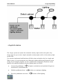
Communication / Network
xLogic offers different ways to communicate within the system.
RS485 port
The RS485 port is used for communication between the main module and various devices
or equipments which have the standard RS485 port .(only ELC-18 Series available, not
applied to ELC-12 series) Communicate using Modbus RTU protocol.
RS232 or USB port
If there is no network required and only one main module with some expansion modules
is needed for the application, the down- and upload of the project to and from the main
module happens over the standard RS232 or USB port. It allows system maintenance like
monitoring too.
11
xLogic SuperRelay
Users Manual
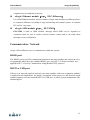
Ethernet network
If the application requires a system where more than one main module is needed and these
main modules have to communicate, each main module will be connected over an
Ethernet Module box to the Ethernet. The project down- and upload to and from the main
modules and the communication between the main modules happens over the Ethernet
network. Furthermore the visualization of the whole system is possible and easy to realize
a personal computer.
12
User’s Manual
xLogic SuperRelay
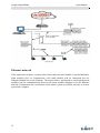
CAN bus
The communication between the main module and the expansion modules or the remote
I/O happens over a CAN bus. CAN is a widely used bus system(only ELC-18 Series
available, not applied to ELC-12 series)
Note
xLogic Main Module may be equipped with expansion modules of the different voltage
class, but expansion module must be supplied the correct power corresponding to its
type.
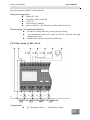
Each xLogic Main Modu le p ro vides the following
connections
for
creation of the circuit program, regardless of the number of connected blocks:
Digital inputs I1 to IC(ELC-18)
,I1 to I8(ELC-12).
Analog inputs AI1 to AI8
Digital outputs Q1 to Q6(ELC-18)
,Q1 to Q4(ELC-12)
Shift register bits S1 to S8
4 cursor keys
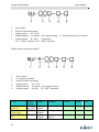
Naming Rules of ELC Series
the
Model name(main module):
13
xLogic SuperRelay
1.
2.
3.
4.
5.
Users Manual
Series name
Points of input and output
Supply power
AC or DC
Digital/Analog
D: digital DA: digital/analog
Output format
R: relay T: transistor
TN = “NPN” transistor; TP= “PNP” transistor
L: with photoelectricity isolation
Model name (expansion module):
1.
2.
3.
4.
5.
6.
Series name
E: expansion module
Points of input and output
Supply power
AC or DC
Digital/Analog
D: digital DA: digital/analog
Output format
R: relay TP: “PNP” transistor;
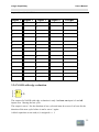
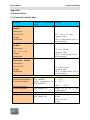
TYPE
ELC12AC-R
ELC12DC-D-R
ELC-12DC-DTP
14
Supply
Voltage
AC110~
AC240V
DC24V
DC24V
Inputs
Outputs
8
digital
8
digital
8
digital
4 relays(10A)
PWM
HMI
RTC
no
yes
4 relays(10A) no
no
yes
4 transistor
(0.3A)
no
yes
no
1 ch(Q4)
User’s Manual
xLogic SuperRelay
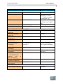
ELC12DC-DA-R
ELC-12DC-DA
-TP
ELC18AC-R
ELC18AC-L-R
DC24V
ELC18DC-D-R
ELC-18DC-DTP
DC24V
ELC18DC-DA-R
DC24V
ELC-18DC-DA
-TP
DC24V
ELC-E-16ACR
ELCE-16DC-D-R
ELCE-16DC-DA-R
AC110~
AC240V
DC24V
DC24V
AC110~
AC240V
AC110~
AC240V
DC24V
DC24V
8 analog
/digital
8 analog
/digital
12 digital
4 relays(10A) no
no
yes
4 transistor
1 ch(Q4)
(0.3A)
6 relays(10A) no
no
yes
yes
yes
12
digital(is
-olation)
12
digital
12
digital
6 relays(10A)
yes
yes
6 relays(10A) no
yes
yes
6 transistor
(0.3A)
yes
yes
yes
yes
yes
yes
8analog/
digital+
4digital
8analog/
digital+
4digital
8 digital
8digital
6digital
+2analog
/digital
no
2
ch(Q5,Q6)
6 relays(10A) no
6 transistor
(0.3A)
2
ch(Q5,Q6)
4 relays(10A) no
+4 relays(3A)
4 relays(10A)
+4 relays(3A)
4 relays(10A)
+4 relays(3A)
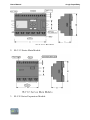
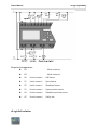
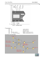
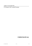
Structure
1. ELC-18 Series Main Module
15
User’s Manual
2. ELC-12 Series Main Module
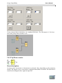
3. ELC-E Series Expansion Module
17
xLogic SuperRelay
xLogic SuperRelay
User’s Manual
2. Installing/removing xLogic
Dimensions
The xLogic installation dimensions are compliant with DIN 43880.
xLogic can be snap-mounted to 35 mm DIN rails to EN 50022 or on
the wall.
xLogic width:
ELC-12 Series Main Module has a width of 72mm.
ELC-18 Series Main Module has a width of 95mm.
ELC-E expansion modules have a width of 72mm .
Note
18
User’s Manual
xLogic SuperRelay
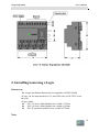
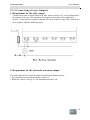
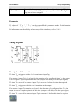
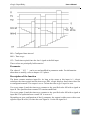
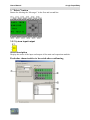
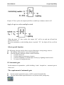
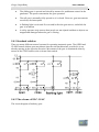
The figure below shows you an example of the installation and removal of an ELC-12AC
main module. The measures shown apply to all other ELC-12 Series versions and
ELC-18 Series versions and expansion modules.
Wa rni ng
Always switch off power before you “remove” and “insert” an expansion
module.
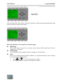
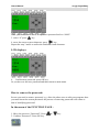
2.1 DIN rail mounting
1. Hook the xLogic Basic module onto the rail.
2. Push down the lower end to snap it on. The mounting interlock at the rear
must engage.
19
xLogic SuperRelay
User’s Manual
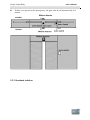
2.2 Wiring the xLogic
Wire the xLogic using a screwdriver with a 3-mm blade.
You do not need wire ferrules for the terminals. You can use conductors with
cross-sections of up to the following thicknesses:
1 x 2.5 mm2
2 x 1.5 mm2 for each second terminal chamber
Tightening torque: 0.4.. .0.5 N/m or 3. ..4 lbs/in
Note
Always cover the terminals after you have completed the i n s t a l l a t i o n . To p r o t e c t
x Lo g i c a d e q u a t e l y f r o m impermissible contact to live parts, local standards must be
complied with.
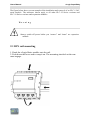
2.2.1 Connecting the power supply
The ELC-18AC and ELC-12AC versions of ELC are suitable for operation with rated
voltages of 110 V AC and 240 V AC. The ELC-18DC and ELC-12DC versions can be
operated with a 12 or 24 VDC power supply. For information on permissible voltage
tolerances, line frequencies and power consumption, refer to the installation instructions
in the Product Information supplied with your device and to the technical data in
Appendix A.
Note
A power failure may cause an additional edge triggering signal.
Data of the last uninterrupted cycle are stored in xLogic.
To connect xLogic to the power supply:
20
User’s Manual
xLogic SuperRelay
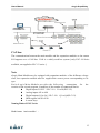
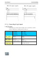
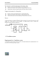
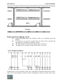
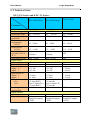
2.2.2 .Connecting xLogic inputs
1. Requirements
At the inputs you connect sensor elements such as: momentary switches,
switches, light barriers, daylight control switches etc.
ELC-18AC
ELC-18DC
ELC-12AC
ELC-12DC
ELC-E-16AC
Signal status 0
ELC-E-16DC
<40VAC
<0.24mA
<3VDC
<1.5mA
Input current
>85VAC
Typical 0.24mA
>8VDC
Typical 3mA
Analogue input
NO
AI1-AI8(0-10V DC)
Input current
Signal status 1
21
xLogic SuperRelay
User’s Manual
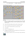
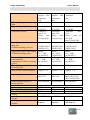
Note:
1. For ELC-18DC Series and ELC-12DC Series versions. That can receive analog
input. They can be set to analog input or switching input as either may be used in
the program. They will be recognized as analog inputs when the input terminal is
connected with an analog function block, and they will be recognized as
switching inputs when the input terminal is not connected with an analog
function block.
2. The analog inputs require DC 0V ~ +10V voltage signals. These are divided
equally in 0.02V increments. In programming, all the block parameters related to
the analog inputs are based on the minimum increment of 0.02V.
3. They can be recognized as switching input when the input voltage is more
than 10.0V and cannot be recognized as an analog input.
4. For the switching input off, when the switch status changes from 0 to 1,
the time of Status 1 must be greater than 50ms, and when the switch status
changes from 1 to 0, the time of Status 0 also must be greater than 50ms.
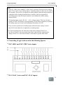
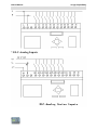
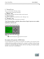
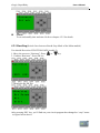
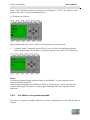
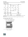
2. Connecting xLogic is shown as in the following figures:
* ELC-18DC and ELC-12DC Series inputs
* ELC-18AC Series and ELC-12AC inputs
22
User’s Manual
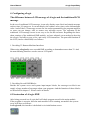
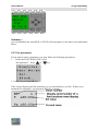
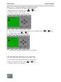
* ELC-Analog Inputs
23
xLogic SuperRelay
xLogic SuperRelay
User’s Manual
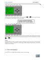
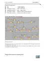
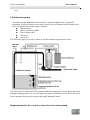
2.2.3 Connecting xLogic Outputs
1. Requirement for the relay output
Various loads such as lamp, fluorescent tube, motor, contact, etc., can be connected to
the outputs of xLogic. The maximum ON output current that can be supplied by
xLogic , is 10A for the resistance load and 2A for the inductive load. The connection is
in accordance with the following figure:
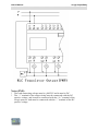
2. Requirement for the electronic transistor output:
The load connected to xLogic must have the following characteristics:
* The maximum switch current cannot exceed 2A.
* When the switch is ON (Q=1), the maximum current is 2A.
24
User’s Manual
xLogic SuperRelay
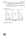
Notes (PNP):
* The load connecting voltage must be ≤80VDC and it must be DC.
* The “+” terminal of the output wiring must be connected with the DC
positive voltage, and it must be connected with the “L+” terminal of the
xLogic power a load must be connected with the “-” terminal of the DC
positive voltage.
25
xLogic SuperRelay
User’s Manual
3 Programming xLogic
ELC series adopts the programming methods by the use of function blocks. A total of 8
general function blocks, 29 special function blocks, and 6 input & output function blocks
are configured. And each block can achieve a specific control function independently, e.g.
TOND, TOFD, SBPL, TBPL, SCHD, etc. As several blocks are linked up in a specific
way, relatively complicated control functions can be performed. Programming with
function blocks is simpler and better appreciated than the conventional PLC instruction
programming.
The following types of operator for xLogic function blocks are available for options:
3.1 General Input & Output functions
3.1.1 Inputs
Input blocks represent the input terminals of xLogic. Up to 260 digital inputs are available
to you.
In your block configuration, you can assign an input block a new input terminal, if this
terminal is not already used in the circuit program.
26
User’s Manual
xLogic SuperRelay
3.1.2 Cursor keys
Up to four cursor keys are available to you. Cursor keys are programmed for the circuit
program in the same ways as other inputs. Cursor keys can save switches and inputs, and
allow operator control of the circuit program.
3.1.3 Outputs
Output blocks represent the output terminals of xLogic. You can use up to 254 outputs. In
your block configuration, you can assign an output block a new terminal, provided this
terminal is not already used in your circuit program.
The output always carries the signal of the previous program cycle. This value doe not
change within the current program cycle.
3.1.4 Permanent logical levels HI and LO
Set the block input to logical hi (hi = high) to set it permanently to logical '1' or 'H' state.
Set the block input to logical lo (lo = low) to set it permanently to logical '0' or 'L' state.
3.1.5 Shift register bits
xLogic provides the shift register bits S1 to S8, which are assigned the read-only attribute
in the circuit program. The content of shift register bits can only be modified by means of
the Shift register special function
27
xLogic SuperRelay
User’s Manual
3.1.6 Analog inputs
You can use up to 88 analog inputs. In your block configuration, you can assign a new
input terminal to an input block, provided this terminal is not already used in the circuit
program.
For help on analog block parameter, refer to Information on analog value processing.
28
User’s Manual
xLogic SuperRelay
3.2 Basic functions list – GF
Basic functions represent simple logical elements of Boolean algebra.
You can invert the inputs of individual basic functions , i.e. the circuit program inverts a
logical “1” at a relevant input to a logical “0”; if “0” is set at the input, the program sets a
logical “1”.
The GF list contains the basic function blocks you can use for your circuit program. The
following basic functions are available:
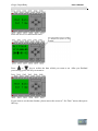
3.2.1 AND
The output of an AND function is only 1 if all inputs are 1, i.e. when they are closed.
A block input that is not used (x) is assigned: x = 1.
Logic table of the AND block:
Input 1
0
0
0
0
0
29
Input 2
0
0
0
0
1
Input 3
0
0
1
1
0
Input 4
0
1
0
1
0
Output
0
0
0
0
0
xLogic SuperRelay
0
0
0
1
1
1
1
1
1
1
1
1
1
1
0
0
0
0
1
1
1
1
User’s Manual
0
1
1
0
0
1
1
0
0
1
1
1
0
1
0
1
0
1
0
1
0
1
0
0
0
0
0
0
0
0
0
0
1
30
User’s Manual
xLogic SuperRelay
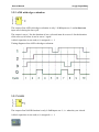
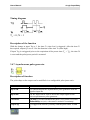
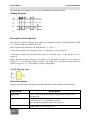
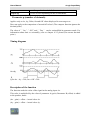
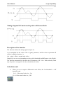
3.2.2 AND with edge evaluation
The output of an AND with edge evaluation is only 1 if all inputs are 1 and at least one
input was 0 during the last cycle.
The output is set to 1 for the duration of one cycle and must be reset to 0 for the duration
of the next cycle before it can be set to 1 again.
A block input that is not used (x) is assigned: x = 1.
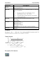
Timing diagram of an AND with edge evaluation
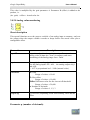
3.2.3 NAND
The output of an NAND function is only 0 if all inputs are 1, i.e. when they are closed.
A block input that is not used (x) is assigned: x = 1.
31
xLogic SuperRelay
User’s Manual
Logic table of the NAND block:
Input 1
0
0
0
0
0
0
0
0
1
1
1
1
1
1
1
1
Input 2
0
0
0
0
1
1
1
1
0
0
0
0
1
1
1
1
Input 3
0
0
1
1
0
0
1
1
0
0
1
1
0
0
1
1
Input 4
0
1
0
1
0
1
0
1
0
1
0
1
0
1
0
1
Output
1
1
1
1
1
1
1
1
1
1
1
1
1
1
1
0
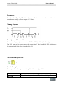
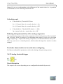
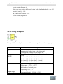
3.2.4 NAND with edge evaluation
The output of a NAND with edge evaluation is only 1 at least one input is 0 and all
inputs were 1 during the last cycle.
The output is set to 1 for the duration of one cycle and must be reset to 0 at least for the
duration of the next cycle before it can be set to 1 again.
A block input that is not used (x) is assigned: x = 1.
32
User’s Manual
xLogic SuperRelay
Timing diagram of a NAND with edge evaluation
3.2.5 OR
The output of an OR is 1 if at least one input is 1 hat, i.e. when it is closed.
A block input that is not used (x) is assigned: x = 0.
Logic table of the OR function:
Input 2
Input 1
33
Input 3
Input 4
Output
0
0
0
0
0
0
0
0
1
1
0
0
1
0
1
0
0
1
1
1
0
1
0
0
1
0
1
0
1
1
0
1
1
0
1
0
1
1
1
1
1
0
0
0
1
1
0
0
1
1
1
0
1
0
1
1
0
1
1
1
1
1
0
0
1
1
1
0
1
1
1
1
1
0
1
1
1
1
1
1
xLogic SuperRelay
User’s Manual
3.2.6 NOR
The output of a NOR (NOT OR) is only 1 if all inputs are 0 hat, i.e. when they are open.
When one of the inputs is switched on (logical 1 state), the output is switched off.
A block input that is not used (x) is assigned: x = 0.
Logic table of the NOR function:
Input 1
Input 2
0
0
0
0
0
0
0
0
1
0
0
1
0
1
0
0
1
0
0
1
1
0
1
1
1
0
0
1
0
0
1
0
1
1
0
1
1
1
0
1
1
0
1
1
1
1
1
1
Input 3
Input 4
0
1
0
1
0
1
0
1
0
1
0
1
0
1
0
1
Output
1
0
0
0
0
0
0
0
0
0
0
0
0
0
0
0
34
User’s Manual
xLogic SuperRelay
3.2.7 XOR
The XOR (exclusive OR) output is 1 if the signal status of the inputs is different.
A block input that is not used (x) is assigned: x = 0.
Logic table of the XOR function:
Input 1
0
0
1
1
Input 2
0
1
0
1
Output
0
1
1
0
3.2.8 NOT
The output is 1 if the input is 0. The NOT block inverts the input status.
Advantage of the NOT, for example: xLogic no longer requires break contacts. You
simply use a make contact and convert it into a break contact with the help of the NOT
function.
Logic table of the NOT function:
Input 1
0
1
Output
1
0
3.3 Basics on special functions
Because of their different input designation, you can see right away that there is a
difference between the special functions and basic functions. SFs contain timer functions,
35
xLogic SuperRelay
User’s Manual
retentive functions and various parameter assignment options, which allow you to adapt
the circuit program to suit your own requirements.
This section provides you with a brief overview of input designations and with some
particular background information on SFs. The SFs in particular are described in
Chapter 4
3.3.1 Designation of the inputs
Logical inputs
Here, you will find the description of the connectors you can use to create a
logical link to other blocks or to the inputs of the xLogic unit.
S (Set):
A signal at input S sets the output to logical “1”.
R (Reset):
The reset input R takes priority over all other inputs and resets the outputs.
Trg (Trigger):
This input is used to trigger the start of a function.
Cnt (Count):
This input is used for counting pulses.
Fre (Frequency):
Frequency signals to be evaluated are applied to this input.
Dir (Direction):
This input determines the direction of count.
En (Enable):
This input enables a block function. When this input is “0”, other signals to the
block will be ignored.
Inv (Invert):
A signal at this input inverts the output signal of the block.
Ral (Reset all):
All internal values are reset.
Parameter inputs
At some of the inputs you do not apply any signals. You configure the
relevant block values instead. Examples:
Par (Parameter):
This input will not be connected. Here, you set the relevant block parameters
36
User’s Manual
xLogic SuperRelay
(times, on/off thresholds etc.).
No (Cam):
This input will not be connected. Here, you configure the time patterns.
P (Priority):
This is an open input. Here, you define priorities and specify whether a
message is to be acknowledged in RUN.
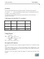
3.3.2 Time response
Parameter T
At some of the SFs it is possible to configure a time value T. When you
preset this time, note that your input values are based on the timebase set:
Timebase
: __
__
1
s (seconds)
seconds :
m (minutes)
minutes : seconds
h (hours)
/100 seconds
hours : minutes
Accuracy of T
Because of slight tolerances in the characteristics of electronic components, the
set time T may deviate. The xLogic has a maximum tolerance of ± 0.02 %.
When 0.02 % of the time T is smaller than 0.02 seconds, the maximum
deviation is 0.02 seconds.
Example: The maximum tolerance per hour (3600 seconds) is ±0.02%,
which is proportional to ± 0.72 seconds. The maximum tolerance per minute
(60 seconds) is ± 0.02 seconds.
Accuracy of the timer (weekly/yearly timer)
To prevent timing inaccuracy of the real-time clock in C versions caused by
this deviation, the timer value is continuously compared with a high-precision
37
xLogic SuperRelay
User’s Manual
time-base and corrected. The resultant maximum timing in accuracy is ± 5
s/day.
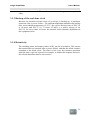
3.3.3 Backup of the real-time clock
Because the internal real-time clock of an xLogic is backed up, it continues
operation after a power failure. The ambient temperature influences the backup
time. At an ambient temperature of 25°C, the typical backup time of ELC-18
is 10 hours and ELC-12 is 72 hours. If there is a power outage of an
ELC-18 for more than 10 hours, the internal clock responds, dependent on
the equipment series.
3.3.4 Retentivity
The switching states and counter values of SFs can be set retentive. This means
that current data are retained after a power failure, and that the block resumes
operation at the break point. The timer is not reset, but resumes operation
until the time-to-go has expired, for example, to enable this response, however,
the relevant functions must be set retentive.
38
User’s Manual
xLogic SuperRelay
3.3.5 Parameter protection
In the parameter protection settings, you can determine whether the
parameters can be displayed and edited in xLogic parameter modify mode
or not.
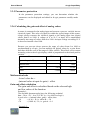
3.3.6 Calculating the gain and offset of analog values
A sensor is connected to the analog input and converts a process variable into an
electrical signal. This value of signal lies within the typical range of this sensor.
xLogic always converts the electrical signals at the analog input into digital
values from 0 to 1000. A voltage of 0 to 10 V at input AI is transformed
internally into range of values from 0 to 1000. An input voltage exceeding 10 V
is shown as internal value 1000.
Because you can not always process the range of values from 0 to 1000 as
predetermined by xLogic, you can multiply the digital values by a gain factor
and then shift the zero of the range of values (offset). This allows you to output
an analog value to the xLogic display, which is proportional to the actual process
variable.
Parameter
Minimum
Maximum
Input voltage (in V)
0
≥ 10
Internal value
0
1000
Gain
–10.00
+10.00
Offset
–10000
+10000
Mathematical rule
Actual value Ax =
(internal value at input Ax∙gain) + offset
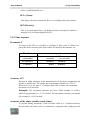
Gain and offset calculation
The gain and offset is calculated based on the relevant high
and low values of the function.
Example 1:
The available thermocouples have the following technical
data: –30 to +70, 0 to 10 V DC (i.e. 0 to 1000 in xLogic).
Actual value = (internal value ∙gain) + offset, thus
–30
= (0 ∙A) + B, i.e. offset B = –30
+70
= (1000 ∙A) –30, i.e. gain A = 0.1
Example 2:
39
xLogic SuperRelay
User’s Manual
A pressure sensor converts a pressure of 1000 mbar into a voltage of 0 V, and a
pressure of 5000 mbar into a voltage of 10 V.
Actual value = (internal value . gain) + offset, thus
1000
5000
= (0·A) + B, i.e. offset B = 1000
= (1000 ∙A) +1000, i.e. gain A = 4
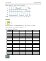
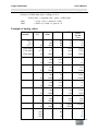
Example of analog values
Process
variable
Voltage
(V)
Internal
value
Gain
Offset
Value
shown
(Ax)
–300 C
00 C
+700 C
1000 mbar
3700 mbar
0
3
10
0
6.75
0
300
1000
0
675
0.1
0.1
0.1
4
4
–30
–30
–30
1000
1000
–30
0
70
1000
3700
5000 mbar
10
0
5
10
0
5
10
0
5
10
0
5
10
0
5
10
0
5
10
0
10
0.02
0.02
0.02
0.02
1000
0
500
1000
0
500
1000
0
500
1000
0
500
1000
0
500
1000
0
500
1000
0
1000
2
2
2
2
4
0.01
0.01
0.01
1
1
1
10
10
10
0.01
0.01
0.01
1
1
1
1
1
1
10
10
0.01
0.1
1
10
1000
0
0
0
0
0
0
0
0
0
5
5
5
500
500
500
–200
–200
–200
–10000
–10000
0
0
0
0
5000
0
5
10
0
500
1000
0
5000
10000
5
10
15
500
1000
1500
–200
300
800
–10000
0
0
0
2
20
40
User’s Manual
xLogic SuperRelay
3.4 Special functions list – SF
When you create your circuit program in xLogicsoft, you find the special function blocks
in the SF list.
You can invert the inputs of SFs individually, i.e. the circuit program converts a logical “1”
at the input into a logical “0”; a logical “0” it converts into a logical “1”. The table also specifies
whether the relevant function can be set retentivity (Rem). The following SFs are
available:
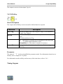
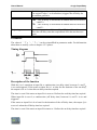
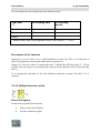
3.4.1 On-delay
Short description
The output is not switched on until a configured delay time has expired.
Connection
Trg input
Parameter
Description
The on delay time is triggered via the Trg (Trigger) input
T represents the on delay time after which the output is switched on
(output signal transition 0 to 1).
Retentivity on = the status is retentive in memory.
Output Q
41
Q switches on after a specified time T has expired, provided Trg is
still set.
xLogic SuperRelay
User’s Manual
Parameter
You select the required function via the block number. Time-base can be adjusted.
The value of "T" can be set/modified in parameter mode. For information about how
to modify,refer to chapter 4.2.2 please.
For information on the validity and accuracy of the time base, refer to the xLogic
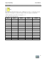
time-base list as follows:
Valid ranges of the time-base, if T = parameter
Time-base
Max. value
Min. resolution
Accuracy
s (seconds)
99:99
10 ms
± 10 ms
m (minutes)
99:59
1s
±1s
h (hours)
99:59
1 min
± 1 min
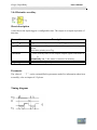
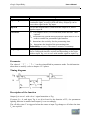
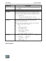
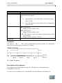
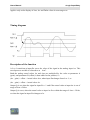
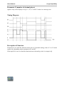
Timing diagram
Description of the function
The time Ta (the current time in xLogic) is triggered with the 0 to 1 transition at input
Trg.
If the status at input Trg stays 1 at least for the duration of the configured time T, the
output is set to 1 when this time has expired (the on signal of the output follows the on
signal of the input with delay).
The time is reset if the status at input Trg changes to 0 again before the time T has
expired.
42
User’s Manual
xLogic SuperRelay
The output is reset to 0 when input Trg is 0.
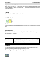
3.4.2 Off-delay
Short description
The output with off delay is not reset until a defined time has expired.
Connection
Input Trg
Description
Input R
Start the off delay time with a negative edge (1 to 0 transition)
at input Trg (Trigger)
Reset the off delay time and set the output to 0 via the R (Reset)
input.
Reset has priority over Trg
Parameter
T:
Output Q
The output is switched off on expiration of the delay time
T (output signal transition 1 to 0).
Retentivity on = the status is retentive in memory.
Q is switched on for the duration of the time T after a trigger at
input Trg.
Parameter
The value of "T"can be set/modified in parameter mode. For information about how to
modify, refer to chapter 4.2.2 please.
For information on the validity and accuracy of the time base, refer to 3.4.1
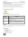
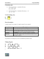
Timing diagram
43
xLogic SuperRelay
User’s Manual
Description of the function
Output Q is set to 1 momentarily with a 0 to 1 transition at input Trg.
At the 1 to 0 transition at input Trg, xLogic retriggers the current time T, and the output
remains set. The output Q is reset to 0 when Ta reaches the value specified in T (Ta=T)
(off delay).
A one-shot at input Trg retriggers the time Ta.
You can reset the time Ta and the output via the input R (Reset) before the time Ta has
expired.
3.4.3 On-/Off-delay
Short description
The on/off delay function is used to set an output after a configured on delay time and
then reset it again upon expiration of a second configured time.
Connection
Input Trg
Parameter
Description
You trigger the on delay with a positive edge (0 to 1 transition) at
input Trg (Trigger).
You trigger the off delay with a negative edge (1 to 0 transition).
TH is the on delay time for the output (output signal transition 0 to
1).
TL is the off delay time for the output (output signal transition 1 to
0).
Retentivity on = the status is retentive in memory.
44
User’s Manual
Output Q
xLogic SuperRelay
Q is switched on upon expiration of a configured time TH if Trg is
still set. It is switched off again upon expiration of the time TL and
if Trg has not been set again.
Parameter
The value of "TH","TL"can be set/modified in parameter mode. For information
about how to modify ,refer to chapter 4.2.2 please.
For information on the validity and accuracy of the time base, refer to 3.4.1
Timing diagram
Description of the function
The time TH is triggered with a 0 to 1 transition at input Trg.
If the status at input Trg is 1 at least for the duration of the configured time TH, the output
is set to logical 1 upon expiration of this time (output is on delayed to the input signal).
The time TH is reset if the status at input Trg is reset to 0 before this time has expired.
The time TL is triggered with the 1 to 0 transition at the output.
If the status at input Trg remains 0 at least for the duration of a configured time TL, the
output is reset to 0 upon expiration of this time (output is off delayed to the input signal).
The time TL is reset if the status at input Trg is returns to 1 before this time has expired.
45
xLogic SuperRelay
User’s Manual
3.4.4 Retentive on-delay
Short description
A one-shot at the input triggers a configurable time. The output is set upon expiration of
this time.
Connection
Input Trg
Input R
Trigger the on delay time via the Trg (Trigger) input.
Description
Parameter
T is the on delay time for the output (output signal transition 0 to
Reset the time on delay time and reset the output to 0 via input R
(Reset).
Reset takes priority over Trg.
1).
Retentivity on = the status is retentive in memory.
Output Q
Q is switched on upon expiration of the time T.
Parameter
The value of "T"can be set/modified in parameter mode.For information about how
to modify, refer to chapter 4.2.2 please.
Timing diagram
46
User’s Manual
xLogic SuperRelay
Description of the function
The current time Ta is triggered with a 0 to 1 signal transition at input Trg. Output Q is set
to 1 when Ta reaches the time T. A further pulse at input Trg does not affect Ta.
The output and the time Ta are only reset to 0 with a1 signal at input R.
If retentivity is not set, output Q and the expired time are reset after a power failure.
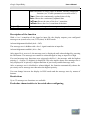
3.4.5 Wiping relay (pulse output)
Short description
An input signal generates an output signal of a configurable length.
Connection
Input Trg
Parameter
Description
You trigger the time for the wiping relay with a signal at input
Trg (Trigger)
TL represents the time after which the output is reset (output
signal transition 1 to 0).
Retentivity set (on) = the status is retentive in memory.
Output Q
A pulse at Trg sets Q. The output stays set until the time T has
expired and if Trg = 1 for the duration of this time. A 1 to 0
transition at Trg prior to the expiration of T also resets the output
to 0.
Parameter
The value of "TL"can be set/modified in parameter mode. For information about how
to modify, refer to chapter 4.2.2 please.
Timing diagram
47
xLogic SuperRelay
User’s Manual
Description of the function
With the input signal Trg = 1, output Q is set to 1. The signal also triggers the time Ta,
while the output remains set.
When Ta reaches the value defined at T (Ta=T), the output Q is reset to 0 state (pulse
output).
If the signal at input Trg changes from 1 to 0 before this time has expired, the output is
immediately reset from 1 to 0.
3.4.6 Edge triggered wiping relay
Short description
An input pulse generates a preset number of output pulses with a defined pulse/pause ratio
(retriggerable), after a configured delay time has expired.
Connection
Input Trg
Input R
Parameter
Description
You trigger the times for the Edge-triggered wiping relay with a
signal at input Trg (Trigger).
The output and the current time Ta are reset to 0 with a signal at
input R.
TL, TH: The interpulse period TL and the pulse period TH are
adjustable.
N determines the number of pulse/pause cycles TL / TH:
Value range: 1...9.
Retentivity set (on) = the status is retentive in memory.
Output Q
Output Q is set when the time TL has expired and is reset when
TH has expired.
Parameter
The value of "TH","TL"can be set/modified in parameter mode. For information
about how to modify ,refer to chapter 4.2.2 please.
48
User’s Manual
xLogic SuperRelay
Timing diagram
TL = 0; N = 1
Description of the function
With the change at input Trg to 1, the time TL (time low) is triggered. After the time TL
has expired, output Q is set to 1 for the duration of the time TH (time high).
If input Trg is retriggered prior to the expiration of the preset time (TL + TH), the time Ta
is reset and the pulse/pause period is restarted.
3.4.7 Asynchronous pulse generator
Description of function
The pulse shape at the output can be modified via a configurable pulse/pause ratio.
Connection
Input En
Input Inv
Description
You enable/disable the asynchronous pulse generator with the
signal at input En.
The Inv input can be used to invert the output signal of the
active asynchronous pulse generator..
Parameter
TL,TH: You can customize the pulse (TL)/ pause (TH) ratio.
Retentivity set (on) = the status is retentive in memory.
Output Q
Q is toggled on and off cyclically with the pulse times TH and
TL .
49
xLogic SuperRelay
User’s Manual
Parameter
The value of "TH","TL"can be set/modified in parameter mode. For information
about how to modify ,refer to chapter 4.2.2 please.
Timing diagram
Description of the function
You can set the pulse/pause ratio at the TH (Time High) and TL (Time Low) parameters.
The INV input can be used to invert the output signal. The input block INV only inverts
the output signal if the block is enabled via EN.
3.4.8 Random generator
Short description
The output of a random generator is toggled within a configurable time.
Connection
Input En
Description
The positive edge (0 to 1 transition) at the enable input En
50
User’s Manual
xLogic SuperRelay
(Enable) triggers the on delay for the random generator.
The negative edge (1 to 0 transition ) triggers the off delay for
the random generator.
Parameter
TH: The on delay is determined at random and lies between 0
s and TH.
TL: The off delay is determined at random and lies between 0
Output Q
s and TL.
Q is set on expiration of the on delay if En is still set. It is reset
when the off delay time has expired and if En has not been set
again.
Parameter
The value of "TH","TL"can be set/modified in parameter mode. For information
about how to modify ,refer to chapter 4.2.2 please.
Timing diagram
Description of the function
With the 0 to 1 transition at input En, a random time (on delay time) between 0 s and TH
is set and triggered. If the status at input En is 1 at least for the duration of the on delay,
the output is set to 1 when this on delay time has expired.
The time is reset if the status at input En is reset to 0 before the on delay time has expired.
When input En is reset 0, a random time (off delay time) between 0 s and TL is set and
triggered.
If the status at input En is 0 at least for the duration of the off delay time, the output Q is
reset to 0 when the off delay time has expired.
The time is reset if the status at input En returns to 1 before the on delay time has expired.
51
xLogic SuperRelay
User’s Manual
3.4.9 Stairway lighting switch
Short description
The edge of an input pulse triggers a configurable time. The output is reset when this time
has expired. An off warning can be output prior to the expiration of this time.
Connection
Input Trg
Parameter
Description
You trigger the time (off delay) for the stairway switch with a
signal at input Trg (Trigger).
T: The output is reset (1 to 0 transition when the time T has
expired.
T! determines the triggering time for the prewarning.
T!L determines the length of the prewarning time.
Retentivity set (on) = the status is retentive in memory.
Output Q
Q is reset after the time T has expired. A warning signal can be
output before this time has expired.
Parameter
The value of "T"can be set/modified in parameter mode.For information about how
to modify, refer to chapter 4.2.2 please.
Timing diagram
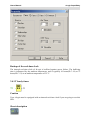
Changing the time base
52
User’s Manual
xLogic SuperRelay
You can change the prewarning time base and the period.
Time base
T
Prewarning time
Prewarning
period
Seconds
Minutes
750 ms
50 ms
15 s
1s
Hours
15 min
1 min
* makes sense only for programs with a cycle time of < 25 ms
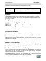
Description of the function
Output Q is set to 1 with a 0 to 1 signal transition at input Trg. The 1 to 0 transition at
input Trg triggers the current time and output Q remains set.
Output Q is reset to 0 when Ta reaches the time T. Before the off delay time (T - T!) has
expired, you can output a prewarning that resets Q for the duration of the off prewarning
time T!L.
Ta is retriggered (optional) at the next high/low transition at input Trg and if Ta is
expiring.
3.4.10 Multiple function switch
Short description
Switch with two different functions:
53
Pulse switch with off delay
Switch (continuous light)
xLogic SuperRelay
Connection
Input Trg
Input R
Parameter
User’s Manual
Description
With a signal at input Trg (Trigger) you set output Q
(continuous light), or reset Q with off delay. Output Q can be
reset with a signal at the Trg input.
You set the current time Ta, and reset the output to 0, with a
signal at input R.
T: The output is reset (1 to 0 transition) when the time T has
expired.
TL determines the period during which the input must be set in
order to enable the permanent light function.
T! determines the on delay for the prewarning time.
T!L determines the length of the prewarning time.
Retentivity set (on) = the status is retentive in memory.
Output Q
Output Q is set with a signal at input Trg, and it is reset again
after a configured time has expired and depending on the pulse
width at input Trg, or it is reset with another signal at input Trg.
Parameter
The value of "T","TL"can be set/modified in parameter mode. For information
about how to modify ,refer to chapter 4.2.2 please.
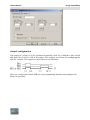
Timing diagram
Description of the function
Output Q is set to 1 with a 0 to 1 signal transition at Trg.
If output Q = 0, and input Trg is set hi at least for the duration of TL, the permanent
lighting function is enabled and output Q is set accordingly.
The off delay time T is triggered when the status at input Trg changes to 0 before the time
TL has expired.
54
User’s Manual
xLogic SuperRelay
Output Q is reset when the Ta = T.
Before the off delay time (T - T!) has expired, you can output an off prewarning that resets
Q for the duration of the off prewarning time T!L. A further signal at input Trg always
resets T and output Q.
Caution
The time base for the T, T! and T!L must be identical.
3.4.11 Weekly timer
Caution
Your xLogic must be equipped with an internal real-time clock if you are going to use this
SFB.
Short description
The output is controlled by means of a configurable on/off date. The function supports
any combination of weekdays.
Connection
Parameter
Output Q
Description
At the No1, No2, No3 (cam) parameters you set the on and off
triggers for each cam of the weekly timer. The parameter units are
the days and the time-of-day.
Q is set when the configured cam is actuated.
Parameter
You can configure a time hysteresis for each individual cam in parameter mode. For
information about how to modify, refer to chapter 4.2.2 please.
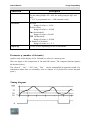
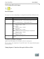
Timing diagram (three practical examples)
55
xLogic SuperRelay
User’s Manual
No1: Daily: 06:30 h to 08:00 h
No2: Tuesday: 03:10 h to 04:15 h
No3: Saturday and Sunday: 16:30 h to 23:10 h
Description of the function
Each weekly timer is equipped with three cams. You can configure a time hysteresis for
each individual cam. At the cams you set the on and off hysteresis. The weekly timer sets
the output at a certain time, provided it is not already set.
The output is reset at a certain time, provided it is not already reset. A conflict is
generated in the weekly timer when the set on time and the set off time at another cam are
identical. In this case, cam 3 takes priority over cam 2, while cam 2 takes priority over
cam 1.
The switching status of the weekly timer is determined by the status at the No1, No2 and
No3 cams.
On times
Any time between 00:00 h and 23:59 h.
Special characteristics to note when configuring
The block properties window offers a tab for each one of the three cams. Here you can set
the weekly on times for the cams. Each tab offers you in addition an option of defining the
on and off times for each cam in hour and minute units. Hence, the shortest switching
cycle is one minute.
You can disable the on and off times individually, i.e. you can achieve switching cycles
extending across more than one day, for example, by setting the on time for cam 1 to
Monday 7:00 h and the off time of cam 2 to Wednesday 13:07 h, while disabling the on
time for cam 2.
56
User’s Manual
xLogic SuperRelay
Backup of the real-time clock
The internal real-time clock of xLogic is buffered against power failure. The buffering
time is influenced by the ambient temperature, and is typically 10 hours(ELC-18) or 72
hours(ELC-12) at an ambient temperature of 25°C.
3.4.12 Yearly timer
Caution
Your xLogic must be equipped with an internal real-time clock if you are going to use this
SFB.
Short description
57
xLogic SuperRelay
User’s Manual
The output is controlled by means of a configurable on/off date
Connection
Parameter
Output Q
Description
At the No (cam) parameter you set the on and off trigger for the
cam of the yearly timer.
Q is set on when the configured cam is switched on.
Parameter
The on and off trigger for the cam of the yearly timer can be set/modified in parameter
mode and you can configure what you need. For information about how to modify, refer
to chapter 4.2.2 please.
Timing diagram
Description of the function
The yearly timer sets and resets the output at specific on and off times.
The off-date identifies the day on which the output is reset again. The first value defines
the month, the second the day.
When you select the every month check box, the yearly clock switches on or off at a
certain day of every month.
Backup of the real-time clock
The internal real-time clock of xLogic is buffered against power failure. The buffering
time is influenced by the ambient temperature, and is typically 10 hours(ELC-18) or 72
hours(ELC-12) at an ambient temperature of 25°C.
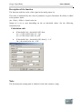
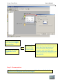
Special characteristics to note when configuring
A click on the dialog box enables direct keyboard input of the month and day values. The
values entered may not exceed the logical maximum of the relevant input boxes,
otherwise xLogicsoft returns an error message.
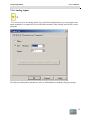
The calendar icon offers you an easy way of setting the date. It opens a window where
you can set the days and months by clicking the relevant buttons.
58
User’s Manual
xLogic SuperRelay
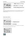
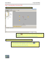
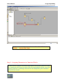
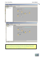
Sample configuration
The output of a xLogic is to be switched on annually, from 1st of March to 4th of April
and from 7th of July to 19th of November. This requires two blocks for configuring the
specific on times. The outputs are then linked via an OR block.
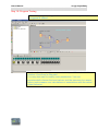
Place two yearly timer switch SFBs on your programming interface and configure the
blocks as specified.
59
xLogic SuperRelay
User’s Manual
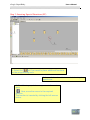
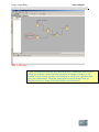
Create a logical link of the blocks via a standard OR block. The OR output is 1 if at least
one of the yearly timer switches is set.
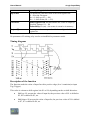
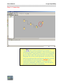
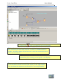
3.4.13 Up/Down counter
Short description
An input pulse increments or decrements an internal value, depending on the parameter
setting. The output is set or reset when a configured threshold is reached. The direction of
count can be changed with a signal at input Dir.
60
User’s Manual
xLogic SuperRelay
Connection
Description
Input R
You reset the output and the internal counter value to zero with a
signal at input R (Reset).
Input Cnt
This function counts the 0 to 1 transitions at input Cnt. It does not
count 1 to 0 transitions.
Use
The inputs I8 (ELC-12) or IB/IC(ELC-18) for
high-frequency counts max. 99 kHz.
Any other input or circuit element for low-frequency
counts (typical 4 Hz).
Input Dir
Input Dir (Direction) determines the direction of count:
Dir = 0: Up
Dir = 1: Down
Parameter
On: On threshold
Value range: 0...999999
Off: Off threshold
Value range: 0...999999
Retentivity set (on) = the status is retentive in memory.
Output Q
Q is set and reset according to the actual value at Cnt and the set
thresholds.
Parameter
The value of "On","Off"and "Cnt"can be set/modified in parameter mode. For
information about how to modify ,refer to chapter 4.2.2 please.
Timing diagram
Description of the function
61
xLogic SuperRelay
User’s Manual
The function increments (Dir = 0) or decrements (Dir = 1) the internal counter by one
count with every positive edge at input Cnt.
You can reset the internal counter value to '000000', with a signal at the reset input R. As
long as R=1, the output is 0 and the pulses at input Cnt are not counted.
Output Q is set and reset according to the actual value at Cnt and the set thresholds. See
the following rules for calculation.
Calculation rule
If the on threshold >= off threshold, then:
Q = 1, if Cnt >= On
Q = 0, if Cnt < Off.
If the on threshold < off threshold, then:
Q = 1, if On <= Cnt < Off.
Caution
The function polls the limit value of the counter once in each cycle.
Thus, if the pulses at the fast inputs (ELC-12) or IB/IC(ELC-18) are faster than the scan
cycle time, the SFB might not switch until the so specified limit has been exceeded.
Example: Up to 100 pulses per cycle can be counted; 900 pulses have been counted so far.
On = 950; Off = 10000. The output is set in the next cycle, after the value has reached
1000.
The output would not be set at all if the value Off = 980
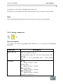
3.4.14 Hours counter
Short description
A configured time is triggered with a signal at the monitoring input. The output is set
when this time has expired.
62
User’s Manual
Connection
Input R
Input En
Input Ral
Parameter
xLogic SuperRelay
Description
A positive edge (0 to 1 transition) at input R resets output Q and
sets a configured value MI at the counter for the duration of the
time-to-go (MN).
En is the monitoring input. xLogic scans the on-time of this input.
A positive edge at input Ral (Reset all) resets both the hours
counter (OT) and the output, and sets the configured value MI at
the counter to for the duration of the time-to-go (MN). That is,
Output Q = 0,
The measured operating hours OT = 0, and
The time-to-go of the maintenance interval MN = MI.
MI: Maintenance interval to be specified in hour units
Range of values: 0000...9999 h
OT: Expired total operation time. An offset can be specified.
Range of values: 00000...99999 h
0:
Q
Output Q
Timing diagram
63
When "R" is selected:
Q = 1, if MN = 0;
Q = 0, if R = 1 or Ral = 1
When "R+En" is selected:
Q = 1, if MN = 0;
Q = 0, if R = 1 or Ral = 1 or En = 0.
The output is set when the time-to-go MN = 0. The output is reset:
When "Q
0:R+En", if
R = 1 or Ral = 1 or En = 0
When "Q
0:R",
if R = 1 or Ral = 1.
xLogic SuperRelay
User’s Manual
MI = Configured time interval
MN = Time-to-go
OT = Total time expired since the last 1 signal at the Ral input
These values are principally held retentive!
Parameter
The value of "MI" can be set and modified in parameter mode. For information
about how to modify, refer to chapter 4.2.2 please.
Description of the function
The hours counter monitors input En. As long as the status at this input is 1, xLogic
calculates the time expired and the time-to-go MN. xLogic displays these times when set
to configuration mode. The output is set to 1 when the time-to-go is equal to zero.
You reset output Q and the time-to-go counter to the specified value MI with a signal at
input R. The operation hour counter OT remains unaffected.
You reset output Q and the time-to-go counter to the specified value MI with a signal at
input Ral. The operation hour counter OT is reset to 0.
Depending on your configuration of the Q parameter, the output is either reset with a reset
signal at input R or Ral, or when the reset signal is 1 or the En signal is 0.
64
User’s Manual
xLogic SuperRelay
Limit value of OT
The value of the operating hours in OT are retained when you reset the hours counter with
a signal at input R. The hours counter OT continues the count as long as En = 1,
irrespective of the status at the reset input R. The counter limit of OT is 99999 h. The
hours counter stops when it reaches this value.
In programming mode, you can set the initial value of OT. The counter starts operation at
any value other than zero. MN is automatically calculated at the START, based on the MI
and OT values.
Example: MI = 100, OT = 130, the result is MN = 70
Parameter preset
In xLogicsoft, you can define MI and an OT start value.
You determine that Q does not depend on En by selecting the corresponding check box.
Retentivity with the hours counter
The hours counter in the xLogic is generally retentive.
However, if the values of the hours counter are lost after a power failure, then select the
respective block in your circuit program. Right mouse click on the hours counter and
select Block Properties > Parameters. The option Retentivity must be activated and not
changeable (grayed out).
If the Retentivity option is not available, then delete the block and insert a new special
function hours counter at the same position.
3.4.15 Threshold trigger
Short description
The output is switched on and off, depending on two configurable frequencies.
65
xLogic SuperRelay
Connection
Input Fre
Parameter
User’s Manual
Description
The function count 0 to 1 transitions at input Fre. ! to 0
transitions are not counted.
Use
Inputs I8(ELC-12) or IB/IC(ELC-18) for fast counts
max. 99 kHz.
Any other input or circuit element for low frequencies
(typical 4 Hz).
On: On threshold
Range of values: 0000...9999
Off: Off threshold
Output Q
Range of values: 0000...9999
G_T: Time interval or gate time during which the input pulses
are measured.
Range of values: 00:05 s...99:99 s
Q is set or reset according to the threshold values.
Parameter
The value of "On","Off"can be set/modified in parameter mode. For information
about how to modify, refer to chapter 4.2.2 please.
Timing diagram
fa = Input frequency
Description of the function
The trigger measures the signals at input Fre. The pulses are captured during a
configurable period G_T.
Q is set or reset according to the set thresholds. See the following calculation rule.
66
User’s Manual
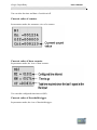
xLogic SuperRelay
Calculation rule
If the threshold (On) > threshold (Off), then:
Q = 1, if fa >= On
Q = 0, if fa < Off.
If the threshold (On) < threshold (Off), then Q = 1, if
On <= fa < Off.
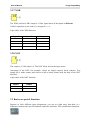
3.4.16 Latching relay
Short description
A signal at input S sets output Q. A signal at input R resets output Q.
Connection
Input S
Input R
Parameter
Output Q
Description
Set output Q with a signal at input S (Set).
Reset output Q with a signal at input R (Reset). Output Q is
reset if S and R are both set (reset has priority over set).
Retentivity set (on) = the status is retentive in memory.
Q is set with a signal at input S and remains set until it is reset
with signal at input R.
No parameter of Latching relay can be set/modified in parameter mode .
Timing diagram
67
xLogic SuperRelay
User’s Manual
Description of the function
The latching relay represents a simple binary memory logic. The output value depends on
the input states and the previous status at the output.
Logic table of the latching relay:
S
0
0
1
1
R
0
1
0
1
Q
x
0
1
0
Remark
Status unchanged
Reset
Set
Reset
When retentivity is enabled, the output signal corresponds with the signal status prior to
the power failure.
3.4.17 Pulse relay
Short description
The output is set and reset with a short one-shot at the input.
Connection
Input Trg
Input S
Input R
Parameter
Output Q
Description
You switch output Q on or off with a signal at input Trg
(Trigger) input.
A one-shot at input S (Set) sets the output to logical 1.
A one-shot at input R (Reset) resets the output to logical 0
Selection:
RS (input R priority), or
SR (input S priority)
Retentivity set (on) = the status is retentive in memory.
Q is switched on with a signal at Trg and is reset again at the
next Trg pulse, if both S and R = 0.
68
User’s Manual
xLogic SuperRelay
No parameter of Latching relay can be set/modified in parameter mode .
Timing diagram
Description of the function
The status of output Q changes with each 0 to 1 transition at input Trg and if both S and R
= 0, i.e. the output is switched on or off.
Input Trg does not influence the SFB when S = 1 or R = 1.
A one-shot at input S sets the pulse relay, i.e. the output is set to logical 1.
A one-shot at input R resets the pulse relay to its initial state, i.e. the output is set to
logical 0.
Either the input R takes priority over input S (i.e. the signal at input S has no effect as
long as R = 1), or the input S takes priority over input R (i.e. the signal at input R has no
effect as long as S = 1), depending on your configuration.
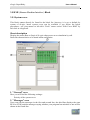
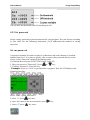
3.4.18 Message text
Short description
Display parameterized message texts and parameters of other blocks in RUN mode.
Connection
Input En
Description
Input P
A 0 to 1 transition at En (Enable) triggers the output of the
message text.
P is the priority of the message text.
1 is the lowest, 32 is the highest priority.
Quit: Acknowledgement of the message text
Parameter
Text: Input of the message text
69
xLogic SuperRelay
User’s Manual
Par: Parameter or actual value of another, already configured
function (see "Visible parameters or actual values")
Time: Shows the continuously updated time-of-day
Date: Shows the continuously updated date
EnTime:Shows the time of the 0 to 1 transition
EnDate:Shows the 0 to 1 transition of the date
Output Q
Q remains set as long as the message text is queued.
Description of the function
With a 0 to 1 transition of the signal at input En, the display outputs your configured
message text (actual value, text, TOD, date) in RUN mode.
Acknowledgement disabled (Ack = Off):
The message text is hidden with a 0 to 1 signal transition at input En.
Acknowledgement enabled (Ack = On):
After input En is reset to 0, the message text is displayed until acknowledged by pressing
the OK button. The message text cannot be acknowledged as long as input En is high.
If several message text functions were triggered with En=1, the message with the highest
priority (1 = lowest, 32=highest) is displayed. This also implies that a new message text is
only displayed if its priority is higher than that of previously enabled message texts.
After a message text is disabled or acknowledged, the function automatically shows the
previously active message text that takes the highest priority.
You can change between the display in RUN mode and the message texts by means of
buttons.
Restrictions
Up to 32 message text functions are available.
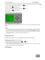
Particular characteristics to be noted when configuring
70
User’s Manual
xLogic SuperRelay
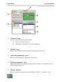
1 "General" area
Here you will find the following settings:·
Priority of the message text
Check box for message text acknowledgement
2 "Blocks" area
Shows a list of all the circuit program blocks and their parameters.
3 "General parameters" area
Shows general parameters such as the current date.
4 "Block parameters" area
Shows the parameters of a block selected from the "Blocks" area which you can
output in the message text.
5 "Insert" button
Button for inserting a parameter selected from the “Block
71
parameters” area.
xLogic SuperRelay
User’s Manual
"Block parameters" or "General parameters" area into the message
text.
6
"Messages" area
You arrange the message text in this area. Information entered in this area
corresponds with that on the xLogic display.
7
"Delete" button
Button for deleting entries from the "Messages" area
"Special characters" button
Button for inserting special characters in the "Messages" area
To arrange the message text
1.
From the "Blocks" area, select the block whose parameters you want to output.
2.
Drag and drop the parameters required from the "Block parameters" to the
"Messages" area. You may also use the "Insert" button to do so.
3.
In the "Messages" area, you can add parameter data as required.
Particular characteristics to be noted when configuring
The message text can be configured in the block properties dialog. You can enter up to 4
lines for each message text (the text display of the xLogic has 4 x 10 characters) and set
the priority. You can move to the next line using the cursor keys or the mouse. Hit the
[ENTER] key to confirm all your entries in the block properties dialog and to close the
dialog.
You may also enter the actual values of other blocks in the text lines. To do so, select the
relevant block from the Block dialog. A Parameter dialog opens to display a list of all
parameters available for the selected block. The block parameter you select in this dialog
is written to the selected text line. The actual parameter value is now included when you
call the message text.
Set the "Acknowledge message" attribute to specify whether a message is be
acknowledged before it is closed.
72
User’s Manual
xLogic SuperRelay
3.4.19 Softkey
Short description
This SFB provides the action of a mechanical pushbutton or switch.
Connection
Input En
Parameter
Description
Output Q is set with a 0 to 1 signal transition at input En
(Enable) and if, in addition, 'Status=On' has been confirmed in
configuration mode.
Type: Sets either a pushbutton action for one cycle or a
switching action of the function.
Status: On or Off state that is applied in the initial cycle after
program startup, is retentivity is not set.
Retentivity set (on) = the status is retentive in memory.
Output Q
Output Q remains set 1, as long as En=1 and the status at the
parameter Type = Switch and Status = On.
Output Q is set for the duration of one cycle if EN=1 and the
status at the parameters Type = momentary (pushbutton) and
Status = On.
The status of this switch can be changed momentarily in parameter mode. For information
about how to modify ,refer to chapter 4.2.2 please.
Factory state
Default of 'Type' is 'momentary action switch'.
Timing diagram
73
xLogic SuperRelay
User’s Manual
Description of the function
The output is set, when input En is set and the 'Status' parameter is set to 'On' and
confirmed with OK. This action is performed irrespective of a configured switch or
pushbutton function.
The output is reset to '0' in the following threes cases:
With a 1 to 0 signal transition at input En.
When a pushbutton function is configured and one cycle has expired after its
actuation.
When the 'Status' parameter sets the 'Off' status in configuration mode, and this
has been confirmed with OK.
Particular characteristics to be noted when configuring
The softkey can be used both with momentary pushbutton or switching action. At the
status parameter you can define the on (actuated) or off state for the switch/pushbutton.
If the softkey is assigned a pushbutton action, the output is always set for the duration of
one cycle with a 0 to 1 transition at input En when the pushbutton is in on state, or if the
pushbutton state changes from Off to On when En=1.
3.4.20 Shift register
Short description
The shift register function can be used to read an input value and to shift the bits. The
output value corresponds with the configured shift register bit. The shift direction can be
changed at a special input.
Connection
Input In
Input Trg
Description
The function when started reads this input value.
The SFB is started with a positive edge (0 t 1 transition) at
74
User’s Manual
Input Dir
Parameter
xLogic SuperRelay
input Trg (Trigger). A 1 to 0 transition is irrelevant.
You define the shift direction of the shift register bits
S1...S8 at the Dir input:
Dir = 0: shift up (S1 >> S8)
Dir = 1: shift down (S8 >> S1)
Shift register bit that determines the value of output Q.
Possible settings: S1 ... S8
Retentivity set (on) = the status is retentive in memory.
Output Q
The output value corresponds with the configured shift
register bit.
No parameter of Latching relay can be set/modified in parameter mode .
Timing diagram
Description of the function
The function reads the value of input In with a positive edge (0 to 1 transition) at input
Trg (Trigger).
This value is written to shift register bits S1 or S8, depending on the set shift direction:
75
Shift up: S1 accepts the value of input In; the previous value of S1 is shifted to
S2, S2 is shifted to S3, etc.
Shift down: S8 accepts the value of input In; the previous value of S8 is shifted
to S7, S7 is shifted to S6, etc.
xLogic SuperRelay
User’s Manual
Q outputs the value of the configured shift register bits.
If retentivity is not enabled, the shift function restarts at S1 or S8 after a power failure.
Note
The special function shift register can be used only once in the circuit program.
3.4.21 Analog comparator
Short description
The output is set and reset depending on the difference Ax - Ay and on two configurable
thresholds.
Connection
Inputs Ax, Ay
Parameter
Description
Input the analog signals of which you want to determine the
delta at the inputs Ax and Ay.
Use the analog inputs AI1...AI8, the analog outputs AQ1
and AQ2.
AI1..AI8: 0 - 10 V corresponds with 0 - 1000 (internal
value).
A: Gain
Range of values: ± 10.00
B: Zero offset
Range of values: ± 10,000
On: On threshold
Range of values: ± 20,000
Off: Off threshold
Range of values: ± 20,000
p: Number of decimals
76
User’s Manual
Output Q
xLogic SuperRelay
Range of values: 0, 1, 2, 3
Q is set or reset depending on the set thresholds.
Parameter p (number of decimals)
Applies only to Ax, Ay, Delta, On and Off values displayed in a message text.
Does not apply to the comparison of on and off values! (The compare function ignores the
decimal point.)
The value of "On","Off"and "Dec" can be set/modified in parameter mode. For
information about how to set/modify ,refer to chapter 4.2.2 please.(Dec means decimal
point.)
Timing diagram
Q for Ax - Ay > 200, On = Off = 200
Description of the function
The function reads the value of the signal at the analog input Ax.
This value is multiplied by the value of parameter A (gain). Parameter B (offset) is added
to the product, hence
(Ax ∙ gain) + offset = Actual value Ax.
(Ay ∙ gain) + offset = Actual value Ay.
77
xLogic SuperRelay
User’s Manual
Output Q is set or reset depending on the difference of the actual values Ax - Ay and the
set thresholds. See the following calculation rule.
Calculation rule
If threshold On ≥Threshold Off, then:
Q = 1, if (actual value Ax - actual value Ay) > On
Q = 0, if (actual value Ax - actual value Ay) ≤Off.
If threshold On < Threshold Off, then Q = 1, falls:
On ≤ (actual value Ax - actual value Ay) < Off.
Reducing the input sensitivity of the analog comparator
You can delay the output of the analog comparator selectively by means of the "on delay"
and "off delay" SFBs. By doing so, you determine that output Q is only set if the input
trigger length Trg (= output of the analog comparator) exceeds the defined on delay time.
This way you can set a virtual hysteresis, which renders the input less sensitive to short
changes.
Particular characteristics to be noted when configuring
For help on analog block parameters, refer to the Analog value processing section.
3.4.22 Analog threshold trigger
Short description
The output is set or reset depending on two configurable thresholds (hysteresis).
78
User’s Manual
Connection
Input Ax
Parameter
xLogic SuperRelay
Description
Input the analog signal to be evaluated at input Ax.
Use the analog inputs AI1...AI8, the analog outputs AQ1 and
AQ2.
0 - 10 V is proportional to 0 - 1000 (internal value).
A: Gain
Range of values: ± 10.00
B: Zero offset
Range of values: ± 10,000
On: On threshold
Range of values: ±20,000
Off: Off threshold
Range of values: ± 20,000
p: Number of decimals
Output Q
Range of values: 0, 1, 2, 3
Q is set or reset depending on the set thresholds.
Parameter p (number of decimals)
Applies only to the display of On, Off and Ax values in a message text.
Does not apply to the comparison of On and Off values! (The compare function ignores
the decimal point.)
The value of "On","Off"and "Dec" can be set/modified in parameter mode. For
information about how to set/modify ,refer to chapter 4.2.2 please.(Dec means decimal
point.)
Timing diagram
79
xLogic SuperRelay
User’s Manual
Description of the function
The function reads the value of the signal at the analog input Ax.
This value is multiplied by the value of parameter A (gain). Parameter B (offset) is added
to the product, hence
(Ax ∙Gain) + Offset = Actual value Ax.
Output Q is set or reset depending on the set threshold values. See the following
calculation rule.
Calculation rule
If threshold (On) ≥ threshold (Off), then:
Q = 1, if the actual value Ax > On
Q = 0, if the actual value Ax ≤Off.
If threshold (On) < threshold (Off), then Q = 1, if
On ≤ the actual value Ax < Off.
Note
The decimal point setting must be identical in the min. and max. range.
80
User’s Manual
xLogic SuperRelay
3.4.23 Analog amplifier
Short description
This SFB amplifies an analog input value and returns it at the analog output.
Connection
Input Ax
Parameter
Description
Input the analog signal to be amplified at input Ax.
Use the analog inputs AI1...AI8, the analog outputs AQ1 and
AQ2.
AI1..AI8: 0 - 10 V corresponds with 0 - 1000 (internal value).
A: Gain
Range of values: ± 10.00
B: Zero offset
Range of values: ± 10000
p: Number of decimals
Range of values: 0, 1, 2, 3
Output AQ
Analog output
Value range for AQ: -32768...+32767
Parameter p (number of decimals)
Applies only to the display of Ax and Ay values in a message text.
Does not apply to the comparison of On and Off values! (The compare function ignores
the decimal point.)
Description of the function
The function reads the value of an analog signal at the analog input Ax.
81
xLogic SuperRelay
User’s Manual
This value is multiplied by the gain parameter A. Parameter B (offset) is added to the
product, i.e.
(Ax ∙gain) + offset = Actual value Ax.
3.4.24 Analog value monitoring
Short description
This special function saves the process variable of an analog input to memory, and sets
the output when the output variable exceeds or drops below this stored value plus a
configurable offset.
Connection
Input En
Description
A positive edge (0 to 1 transition) at input En saves the
analog value at input Ax ("Aen") to memory and starts
monitoring of the analog range Aen ± Delta.
Input Ax
You apply the analog signal to be monitored at input Ax.
Use the analog inputs AI1...AI8, the analog outputs AQ1
and AQ2.
0 - 10 V is proportional to 0 - 1000 (internal value).
Parameter
A: Gain
Range of values: ± 10.00
B: Zero offset
Range of values: ± 10,000
Delta: Difference value for the Aen on/off threshold
Range of values: ± 20,000
p: Number of decimals
Range of values: 0, 1, 2, 3
Output Q
Q is set/reset, depending on the stored analog value and the
offset.
Parameter p (number of decimals)
82
User’s Manual
xLogic SuperRelay
Applies only to the display of Aen, Ax and Delta values in a message text.
Timing diagram
Description of the function
A 0 to 1 transition at input En saves the value of the signal at the analog input Ax. This
saved process variable is referred to as Aen".
Both the analog actual values Ax and Aen are multiplied by the value at parameter A
(gain), and parameter B (offset) is then added to the product, i.e.
(Ax ∙ gain) + offset = Actual value Aen, when input En changes from 0 to 1, or
(Ax ∙ gain) + offset = Actual value Ax.
Output Q is set when the signal at input En = 1 and if the actual value at input Ax is out of
range of Aen ± Delta.
Output Q is reset, when the actual value at input Ax lies within the range of Aen +- Delta,
or when the signal at input En changes to lo.
83
xLogic SuperRelay
User’s Manual
3.4.25 Analog differential trigger
Short description
The output is set and reset depending on a configurable threshold and a differential value.
Connection
Input Ax
Parameter
Description
You apply the analog signal to be analyzed at input Ax.
Use the analog inputs AI1...AI8, the analog outputs AQ1 and
AQ2.
0 - 10 V is proportional to 0 - 1000 (internal value).
A: Gain
Range of values: ± 10.00
B: Zero offset
Range of values: ± 10,000
On: On threshold
Range of values: ±20,000
Delta: Differential value for calculating the off parameter
Range of values: ± 20,000
p: Number of decimals
Output Q
Range of values: 0, 1, 2, 3
Q is set or reset, depending on the threshold and difference
values.
Parameter p (number of decimals)
Applies only to the display of On, Off and Ax values in a message text.
Does not apply to the comparison of On and Off values! (The compare function ignores
the decimal point.)
Timing diagram A: Function with negative difference Delta
84
User’s Manual
xLogic SuperRelay
Timing diagram B: Function with positive difference Delta
Description of the function
The function fetches the analog signal at input Ax.
Ax is multiplied by the value of the A (gain) parameter, and the value at parameter B
(offset) is added to product, i.e.
(Ax ∙ gain) + offset = actual value of Ax.
Output Q is set or reset, depending on the set (On) threshold and difference value (Delta).
The function automatically calculates the Off parameter: Off = On + Delta, whereby Delta
may be positive or negative. See the calculation rule below.
Calculation rule
When you set a negative differential value Delta, the On threshold >= Off
threshold, and:
Q = 1, if the actual value Ax > On
Q = 0, if the actual value Ax ≤ Off.
85
xLogic SuperRelay
User’s Manual
See the timing diagram A.
When you set a positive differential value Delta, the On threshold < the Off
threshold, and Q = 1, if:
On ≤ the actual value Ax < Off.
See the timing diagram B.
3.4.26 Analog multiplexer
Short Description
This special function displays 0 or one of 4 saved analog values on the analog output.
Connection
Input En
Description
Inputs S1
and S2
1 on input En (Enable) switches, dependent on S1 and S2, a
parameterized analog value to the output AQ.
0 on input EN switches 0 to the output AQ.
S1 and S2 (selectors) for selecting the analog value to be
issued.
S1 = 0 and S2 = 0: The value 1 is issued
S1 = 0 and S2 = 1: The value 2 is issued
S1 = 1 and S2 = 0: The value 3 is issued
S1 = 1 and S2 = 1: The value 4 is issued
Parameter
V1...V4: Analog values (Value) that will be issued.
Value range: -32768...+32767
p: Number of decimal places
value range: 0, 1, 2, 3
Output AQ
Analog output
Value range for AQ: -32768...+32767
86
User’s Manual
xLogic SuperRelay
Parameter P (number of decimal places)
Applies only to the display of AQ, V1, V2, V3 and V4 values in a message text.
Timing Diagram
Description of Function
If input En is set, then the function issues one of 4 possible analog values V1 to V4 at the
output AQ, depending on the parameters S1 and S2.
If the input En is not set, then the function issues the analog value 0 at output AQ.
87
xLogic SuperRelay
User’s Manual
3.5 HMI (Human Machine Interface) Block
3.5.1System cover
This block cannot directly be found in the block list ,however, it is set as default by
system of xLogic, hence system cover can be available if you follow the below
procedures : use your mouse to left-click “Tools” menu->select “Edit Cover HMI” by
left-click in xLogicsoft .
Short description
Display the status (Run or Stop) of xLogic when power-on or simulation by soft.
Particular characteristics to be noted when configuring
1. "General" area
Here you will find the following settings:·
Priority of the system cover
2. "Messages" area
Users can edit the messages in the first and second line, the third line displays the state
RUN or STOP, and the messages saying whether your program has mistakes or not will be
shown in the fourth line.
88
User’s Manual
xLogic SuperRelay
3. "Delete" button
Button for deleting the “Messages” in the first and second line.
3.5.2 System input/output
Short description
Display the status of the input and output of the main and expansion modules.
Particular characteristics to be noted when configuring
89
xLogic SuperRelay
User’s Manual
1. "General" area
Here you will find the following settings:
Priority of the system input and output.
2. "Blocks" area
Displaying all extendable and main modules can be inserted
3. "Insert" button
Button for inserting the selected blocks to the “Message” area.
4. "Message" area
Display input and output of the blocks you inserted.
The following figure would be shown when xLogic is power-on or under
simulation status in soft.
Note:
represents high pulse,
represents low pulse.
Description of the priority of HMI blocks:
If several HMI blocks are placed in the program, the messages in the respective block
would be displayed according to priority level (1 = lowest, 32 = highest). After a message
is disabled or acknowledged, the function automatically shows the previously active
message text that takes the highest priority, but you can change the human machine
interface via press the Left and Right key.
90
User’s Manual
xLogic SuperRelay
4. Configuring xLogic
The difference between LCD message of xLogic and the traditional LCD
message
In the use of traditional LCD message, it can only display some fixed and simple message
such as time, I/O status etc. It can not display the counter value, timer value and analogue
value. And all the LCD message screens are set and programmed by the program engineer,
so users can not change, add, or remove any message screen. The operation of the
traditional LCD message screen is not easy to use for the end users. Regarding the above
short comings of the traditional HMI module, we have adopted a new method to develop
the xLogic, and offer to user a free, and easily LCD instruction. The powerful function of
the LCD (can be called HMI) is as follows:
1. Providing 32 Human-Machine Interfaces
When using xLogicsoft, users can add HMI according to demand not more than 32. And
the non-alarming interfaces can be seen on LCD panel.
2. Providing Several HMI Blocks
Besides the system cover and system input/output blocks, the message text block can
supply a large number of messages about your program. And the function of those blocks
are described in chapter 3. Please read it in details.
4.1 Instruction of xLogic-HMI
After being powered on, xLogic shall self-check program stored in the main module.
If the program is accurate, then the main module will be running, meanwhile the system
cover will show as follows:
In xLogicsoft, this interface is defaulted as its initialization screen.
91
xLogic SuperRelay
If there are several parameter pages, users may press
you would like. The last page is the cursor mode:
User’s Manual
or
key to go to the page
If xLogic has several alarm interfaces in the same period and it only displays the message
with highest priority in the block, also you may go through all alarm messages by pressing
or
key.
Note:
The message text block would be treated as parameter page only when it has no input,
otherwise, it may be regarded as alarm page. When input has high pulse, LCD shall
display alarm message.
4.2 Select function page
Press ESC key to change from running mode to function page.
92
User’s Manual
xLogic SuperRelay
After pressing ESC key, xLogic would be switched to function page and meanwhile open
function menu as figure below shows.
Brief introduction on four options of function page:
Run/stop
Select this menu to switch over xLogic status between RUN and Stop. Refer to
chapter4.2.1 for details.
Set Param
To set function block parameter. Refer to chapter 4.2.2 for details.
Set…
Used to set /modify password and set address of expansion module, refer to chapter
4.2.3 and 4.2.4 for details please.
1.
2.
93
”Press
or
key to move the cursor to “Set….
Then press OK key ,xLogic will display as follows:
xLogic SuperRelay
User’s Manual
Clock
To set and modify date and time .Refer to chapter 4.2.5 for details.
4.2.1 Run/Stop(Switch Over between Run & Stop Mode of the Main module)
You should first select FUNCTION PAGE.(read 4.2)
1. Move the cursor to “Run/stop”: Press
2. Confirm “Run/stop” :Press OK key.
or
key.
3.Then press the OK key.
After pressing ESC key, you’ll find out your circuit program has changed to “stop” status
as figure below shows:
94
User’s Manual
xLogic SuperRelay
Summary:
you can transform the state(RUN or STOP) of the program via the three steps mentioned
above.
4.2.2 Set parameter
If you want to select a parameter, you may follow the following procedures:
1. Under the FUNCTION PAGE, select
“Set parameter” : Press
or
key
2. Confirm by pressing OK key.
Then xLogic displays the first parameter, so you can modify as you like. If there is no
parameter to set/modify, you can press ESC key to return.
95
xLogic SuperRelay
User’s Manual
3. Select parameter you intend to modify.
4. Select certain specific value of that parameter which you want to edit ,then press OK
key.
How to modify parameter?
A. First select certain parameter which you need to edit by following the below
procedures:
1. Under the FUNCTION PAGE, select
“Set parameter”: Press
or
key
2. Confirm by pressing OK key.
B. then you can perform the below actions to modify parameter:
1.
Move the cursor to the parameter to be modified: press
2.
3.
or
key.
Modify value: press
Confirm the value after modification: press OK key.
or
key.
96
User’s Manual
xLogic SuperRelay
Note:
When xLogic is running, not only time value but also time unit(S,M,H) can be altered ,
but Besides alter time parameter at RUN time ,you can alter time base(s=second,
m=minute ,h=hour).
Current value of time T
View time T in parameter mode:
You are allowed to modify configuration time. Switch on/off time for a time segment.
In parameter mode, time segment figure of a timer:
97
xLogic SuperRelay
User’s Manual
You can alter the time and date of switch on/off.
Current value of counter
In parameter mode, the parameter view of a counter:
Current value of hour counter
In parameter mode, the view of hour counter:
You can edit configured time interval (MI).
Current value of threshold trigger
In parameter mode, the view of threshold trigger:
98
User’s Manual
xLogic SuperRelay
You can alter the threshold value of switching on /off.
4.2.3 Set password
xLogic supply password protection function for your program. You can choose according
to your need. See the following instruction, you’ll understand the method of setting
password.
Set one password
A password contains less than or equal to 4 characters and each character is Arabian
number from 0 to 9 .It is easy to specify, edit or remove the password directly on the
xLogic in the “Password” menu of the function page:
You should first select the FUNCTION PAGE. (read 4.2)
or
key.
1. Move the cursor to “Password”: Press
2. Confirm “Password”: Press OK key.
Example: let us set “1234” as password for a program. Now the LCD displays the
following interface:
Select “New” option, then edit it.
3.select “1”:press
key once.
4. move the cursor to the next character: press
5. select “2”:press
99
key twice.
key.
xLogic SuperRelay
User’s Manual
6. move the cursor to the next character: press
7.select”3”:press
key.
key three times.
8. move the cursor to the next character: press
9.select “4”:press
Now display:
key.
key four times.
10. Confirm password: press OK key.
Now, the program is protected by the password of “1234”, then you can return to the main
menu.
Note:
You can cancel a password newly-set via ESC key. In this instance, xLogic will return
to main menu and not reserve that password. You also can use xLogicsoft to set your
password. You are not allowed to edit the program protected by password or transfer it
to xLogicsoft unless you input a true password previously.
Modify password:
In order to modify password, you are required to present current password.
In the menu of the FUNCTION PAGE.:
1. Move the cursor to “Password”: Press
or
key.
2. Confirm “Password”: Press OK key.
Select “Old” and input primary password (in our instance is “1234”), the process is the
same as the step 3 to step 10 mentioned above.
LCD displays:
100
User’s Manual
xLogic SuperRelay
Thus, you could select “New” to input new password such as “8888”:
3. select “8”:press
key.
key.
4. move the cursor to next character: press
Repeat the step 3 and 4 to realize the third and fourth character.
LCD displays:
4. Confirm new password: press OK key.
So you have set the new password and then return to main menu.
How to remove the password:
In case you need to remove password .e.g. allow the other users to edit your program, then
you must know the current password. the process of removing password is the same as
that of modifying password.
In the menu of the FUNCTION PAGE. :
1. Move the cursor to “Password”: Press
2. Confirm “Password”: Press OK key.
101
or
key.
xLogic SuperRelay
User’s Manual
Select “Old” and input primary password (in our instance is “1234”), the process is the
same as the step 3 to step 10 mentioned above.
LCD displays as follows:
Input nothing under the “New”, and let it keep blank to clear password.
5.
Confirm “blank” password: press OK key. Now you have cleared password and
return to main menu. If you want to set password next time ,the LCD will display:
Note:
This action (removal) make password alert be prohibited , so your program can be
reserved without password.
If users input wrong password and press OK key, xLogic doesn’t enter edit page and
return to main page. This process repeats again and again until you input the correct
password.
4.2.4
Set Address of expansion module
You may set expansion module address to realize communication with main module of
xLogic.
102
User’s Manual
xLogic SuperRelay
Note: Up to 31 expansion modules can be linked together.
You shall first select the FUNCTION PAGE.(read 4.2)
1. Move the cursor to “Set adr”: Press
2. Confirm “Set adr” :Press OK key.
or
key.
3.
Move the cursor to the place of parameter to be modified: press
6.
Modify value: press
7.
Confirm the value after modification: press OK key.
or
key.
4.2.5 Modification Methods of System Time
You should first select the FUNCTION PAGE.(read 4.2)
1. Move the cursor to “Clock”: Press
2. Confirm “Clock” :Press OK key.
103
or
key.
or
key.
xLogic SuperRelay
User’s Manual
Press OK key to set and modify date.
Press
or
key to realize the date which you want to set .After you finished
your setting, press OK key to return to :
If you want to set the time further, please move the cursor to” Set Time” menu, then press
OK key:
104
User’s Manual
xLogic SuperRelay
Here you can set week day (From Monday to Sunday)and the clock. The method is
similar to above. After completion of your setup, press OK key:
Press ESC key and return to FUNCTION PAGE.
5. Application
In order to let users know the far going application field of xLogic, we present a set of
application example. Each instance includes the circuit program of its original solution
and the compare of solution in which xLogic has been applied.
You can find the following solution:
Dual-function switch
Automatic gate
Ventilation system
Industry door
Daylight lamps
Rain water pump
105
xLogic SuperRelay
User’s Manual
Note:
The application example of xLogic is available free of charge to our clients, but we can’t
make any promise, it is only to explain the general rule of using xLogic. It is possible that
these instances can be different from user’s specific application, so user should take all
related responsibility of running those instance systems, and we sincerely suggest user
shall refer to relevant nation standard and installation rules related to systems.
Also, we have to point out that error is unavoidable, and we reserve the according
modification rights.
5.1 Dual-function switch
Requirements for stairway lighting systems
The basic requirements for a stairway lighting system are as follows:
When someone is using the stairs, the stairway lights should be on.
If no one is in the stairway, the lights should go out in order to save energy.
5.1.1 Standard solution
Up to now two methods were known to control such a lighting system:
Pulse relay: When the lights are off, press any of the pushbuttons to switch on
the lights. When the lights are on, press any of the pushbuttons to switch off the
lights again.
Disadvantage: People often forget to switch off the lights
Automatic stairway light switch: Press any one of the pushbuttons to switch on
the lights. The lights switch off again automatically when a preset off delay time
has expired.
Disadvantage: You can't keep the lights switched on over an extended period of
time. The permanent on switch, usually installed inside the stairway lighting
timer unit, may be difficult or impossible to access.
The wiring is the same for both systems.
106
User’s Manual
xLogic SuperRelay
xLogicSoft solution
The xLogic system can replace the automatic stairway light switch or the pulse relay.
xLogic also lets you create a simple automatic stairway light switch via the stairway light
switch SFB.
You can also implement both functions (off delay timer and pulse relay) in a single unit.
What is more, you can incorporate extra functions without making any alterations to the
wiring. In our example program, we have combined the advantages of both the current
impulse relay and the automatic stairway lighting timer as follows:
Actuate the pushbutton
The light is switched on and switched off again on
expiration of a predefined time.
Hold the pushbutton down
Press the pushbutton once more
107
Switches on continuous lighting
Switches off the lighting
xLogic SuperRelay
User’s Manual
5.1.2 The scheme of ELC18AC
The wiring of a lighting system with xLogic is the same as standard corridor or stairway
lighting systems. Only the automatic lighting timer/pulse relay is replaced.
xLogic lets you quickly and easily combine all those functions in a single dual-function
switch SFB, without additional wiring and expenditure.
Apply pulse relay of xLogic
When the input “I1” has a pulse, the output “Q1”will be on or off.
Automatic stairway lighting system
108
User’s Manual
xLogic SuperRelay
If input “I1”has a pulse, the output Q1will be on and keep 6 minutes, then be off.
Apply xLogic to realize multiple switch
When the input “I1” has a pulse ,the output “Q1” will be on and not off until the
period“TH”be over.
Keep the momentary switch holding down in period “TL”, the light will be on all the
time.
Select special function
The following selection can be done as special function or saving energy sources:
The lighting flicker before it gets off automatically.
You can integrate different central control functions:
Central control off
Central control on(emergency button)
Control all lighting or certain single circuitry by lighting control switch.
To control by integrated timer.
5.2 Automatic gate
In the entrance of supermarket、public building、bank、hospital etc,automatic gate is
often used.
The requirement of automatic gate
109
If some people approach to gate, it will be opened automatically.
The gate must remain open until there is no person on the passageway.
xLogic SuperRelay
User’s Manual
If there is no person on the passageway, the gate must be off automatically in a
minute.
5.2.1 Standard solution
110
User’s Manual
xLogic SuperRelay
As long as the detector B1 or B2 detects someone approach, the switch K3 will be on and
open the door.
If the two detectors don’t detect person in a short time, trigger K4 and close the door.
5.2.2 The scheme of ELC 18 AC
111
xLogic SuperRelay
Required components:
K1
K2
S1(break contact)
S2(break contact)
B1(make contact)
B2(make contact)
User’s Manual
open contactor
close contactor
close limit switch
open limit switch
outdoor infrared action detector
infrared action detector inside
xLogic function block circuit program:
Motion detector
During business hours, if someone enters store, the detector B1 will trigger electricmotor
to open the door, vice versa.
At closing time, the detector B2 make electromotor keep running for an hour to make
more time for customer to leave.
Trigger electromotor for opening door
112
User’s Manual
xLogic SuperRelay
The output Q1 is switched on and triggers electromotor, when:
Operate control switch I5(the door is open all the time)
The detector indicates that somebody is approaching to the door.
The door has not been opened entirely (I4 limit switch is not off.).
Trigger electromotor for closing door
Operate control switch I6(the door is closed all the time )
The detector indicates that nobody is approaching the door.
The door had not been closed entirely (I3 limit switch is not off).
Buzzer
Connect the buzzer to output Q3.When the door is going to be closed, the buzzer gives off
sounds for a short time(1s in this example). To attach buzzer, need to connect the
following circuit program to output Q3.
5.3 Ventilation system
Requirements for a Ventilation system
A Ventilation system supplies fresh air into a room and exhausts the contaminated air. Let
us look at the following sample system:
113
xLogic SuperRelay
User’s Manual
A room contains an extractor fan and a fresh-air fan.
Each fan is monitored by means of a flow sensor.
The pressure in the room may rise above the atmospheric pressure.
The fresh-air fan may only be switched on if the flow sensor signals the safe
operational state of the extractor fan.
A warning lamp indicates failure of one of the fans.
5.3.1 Standard solution
The control circuit diagram of Ventilation system formerly as follows:
114
User’s Manual
xLogic SuperRelay
The fans are monitored by means of flow sensors. If no air flow is registered after a short
delay time has expired, the system is switched off and an error message is generated,
which can be acknowledged by pressing the off button.
Fan monitoring requires an analyzer circuit with several switching devices, in addition to
the flow sensors. A single xLogic device can replace this analyzer circuit.
5.3.2The scheme of ELC-18 AC
The circuit diagram of ventilation system:
115
xLogic SuperRelay
User’s Manual
Required components:
K1
Main contactor
K2
Main contactor
S0(make contact)
Off button
S1(make contact)
On button
S2(break contact)
Flow monitor
S3(break contact)
Flow monitor
H1
Flashing lamp
H2
Flashing lamp
xLogicSoft solution
The use of xLogic reduces the amount of switchgear. Thus, you save installation time and
space in the control cabinet. You may even be able to use as a smaller control cabinet.
With xLogic you can also switch off of the fans sequentially after the system is switched
off.
The circuit in xLogicSoft
The system is switched on and off at the inputs I1 and I2. The fans are connected to
outputs Q1 and Q2, the flow sensors are connected to the inputs I3 and I4. Blocks B07
and B10 are used to set the watchdog times after which the flow sensors should send a
signal to the fault output Q3.
116
User’s Manual
xLogic SuperRelay
You can invert output Q3 to use output messages at Q4. Relay Q4 only drops out if main
power is lost or if there is a fault in the system. The output can then be used for a remote
message.
5.4 Factory door
Requirements for a gate control system
In many cases a factory entrance is closed with roll gates. Those gates are only opened
when vehicles need to enter or leave the factory grounds. The gate is controlled by the
porter.
117
xLogic SuperRelay
User’s Manual
The sliding gate is opened and closed by means of a pushbutton control in the
gatehouse. The porter can monitor the gate operation.
The roll gate is normally fully opened or it is closed. However, gate movements
can always be interrupted.
A flashing light is activated five seconds before the gate moves, and while the
gate is in motion.
A safety pressure strip ensures that people are not injured and that no objects are
trapped and damaged when the gate is closing.
5.4.1 Standard solution
There are many different control systems for operating automatic gates. The OPEN and
CLOSE buttons initiate gate movements into the relevant direction, provided it is not
already moving in the opposite direction. Movement of the gate is terminated either by
means of the STOP button or the relevant limit switch.
5.4.2 The scheme of ELC-18 AC
The circuit diagram of industry gate:
118
User’s Manual
xLogic SuperRelay
Required components:
K1
Main contactor
K2
Main contactor
S0
(break contact) Off button
S1
(make contact)
Open button
S2
(make contact)
Shutdown button
S3
(break contact) Open position sensor
S4
(break contact) Shutdown position sensor
S5
(break contact) Safety bar
xLogicSoft solution
119
xLogic SuperRelay
User’s Manual
A xLogic circuit provides a further feature compared to standard controls: The actuation
of a safety bar interrupts the closing motion of the gate. Five seconds before the gate is
opens or closes, a flashing light is activated and signals the start of the movement. It
continues flashing until the gate has stopped.
In contrast to standard solutions, xLogic offers an easy and economic means of modifying
the control system.
5.5 Daylight lamp system
120
User’s Manual
xLogic SuperRelay
Requirements for lighting system:
Different daylight lamp rows should be able to be switched on and off
handily.
If window at one side has enough light, the light will be switched off
automatically via lightness sensitivity switch.
The light would be switched off automatically at 8:00 p.m.
The light can be switched on and off manually at any time.
5.5.1 Standard solution
Lighting lamp can be operated by pulse relay controlled by button besides the door. Pulse
relay can be repositioned by means of timer and lightness sensitivity switch. Pulse relay
121
xLogic SuperRelay
User’s Manual
may shorten pulse width of “off command”.
Required component:
Button S1—S4
Daylight control switch B1
Timer T1
Pulse relay K1 and K2
pulse switch K3—K6 able to be switched off collectively
Disadvantages of traditional solution:
In order to realize function, it need plenty of wiring .
Vast mechanical parts will result in obvious abrasion and high
maintenance costs.
Modification function can cause much work.
5.5.2 The scheme of ELC-18AC
Components:
S1—S4(make contact)
Momentary switch
122
User’s Manual
xLogic SuperRelay
B1(make contact)
Daylight
control switch
Circuit diagram by xLogicsoft:
Benefits:
While power consumption of load does not exceed output of switch’s voltage range,
lamp can be directly connected to xLogic main module, however, if power
consumption of load exceeds output of switch’s voltage range, then power contactor
would be required.
You can connect directly lightness sensitivity switch to the input of xLogic.
Don’t need external timer, as this function has been integrated in xLogic.
It can be installed in a small-sized cabinet, so quite space-saving.
Less equipment
Quite easier to modify lighting system
According to your demand, you may setup supplementary on/off timing (lamp can
be switched off in order at the end of day.
Easier to apply role of lightness sensitivity switch to lamp or already modified lamp
123
xLogic SuperRelay
User’s Manual
row.
5.6 Rainwater pump
Nowadays besides drinkable water in family, rainwater applications is gradually
increasing. In this way much costs can be saved, also environment can be improved as
well. The application of rain water as follows:
Wash clothes
Water system in garden
Potted plant water
Wash car
Scour W.C.
The following figure is to tell you how to run the rainwater application system:
The rain water is collected in the container and then pumped to service water ductwork
through pumping station. So you can apply rain water as drinkable water. If the rain water
in the container dried up, this system can supply drinkable water.
Requirements for the control system of service water pump
124
User’s Manual
xLogic SuperRelay
It can provide service water all day, under the contingency instance, the
control system must be able to be switched over to drinkable water
system automatically.
When switching to drinkable water system, it can’t interlard rain water.
If rain container has not enough rain water, service water pump can’t be
on (rain water dry-up protection).
5.6.1 Standard solution
5.6.2 The scheme of ELC-18AC
125
xLogic SuperRelay
User’s Manual
Components:
K1
Y1
S1
S2(make contact)
S3—S4(break contact)
main contactor
Solenoid valve
Pressure switch
Bobber switch(water level)
Bobber switch(water level)
Function block diagram:
126
User’s Manual
xLogic SuperRelay
6. xLogic Software
xLogic soft is available as a programming package for the PC. This software
provides many features, for example:
A graphic interface for offline creation of your circuit program by means of
Function Block Diagram (function chart)
Simulation of your circuit program on the PC
Generating and printing of an overview chart for the circuit program
Saving a backup of the circuit program on the hard drive or other media
Comparing circuit programs
Easy configuration of blocks
Transferring the circuit program
– from the xLogic to the PC and
– from the PC to xLogic
Setting the TOD
Online test: Display of status changes and process variables of xLogic in
RUN mode:
– Status of a digital I/O, shift register bits and cursor keys
– The values of all analog I/Os
– The results of all blocks
– The current values (including the times) of selected blocks
Starting and stopping circuit program execution via the PC (RUN,
STOP).
The xLogic alternative
As you can see, xLogic Soft represents an alternative to conventional
engineering methods:
1. You start by developing the circuit program on your desktop.
2. You simulate the circuit program on your computer and verify its functions,
before you actually implement it in your system.
3. You can add comments to the circuit program and create hardcopies.
4. You save a copy of your circuit program to the file system on your PC, to
make it directly available for any modifications.
5. It takes only a few key actions to download the circuit program to xLogic.
127
xLogic SuperRelay
User’s Manual
xLogicSoft
xLogicsoft runs under Windows 95/98,
Windows NT 4.0, Windows Me ® , Windows 2000 ® , Windows XP ® ,
xLogicsoft is capable of client/server operation and offers you a high degree
of freedom for creating your circuit program.
xLogicSoft: xLogicV2.0
This is the current version of xLogicsoft. You will find all the functions and the
functionality of the devices described in this manual in the version 2.0 and
later.
Note
If a full version is not installed, you can carry out an upgrade as follows:
Install the software from the CD.
When the system prompts you for the previous version, place the old
xLogicsoft CD in CD drive.
Point your browser to the “...\Install” directory on the CD.
Updates and info
You can download demo versions of the software free of charge from the
Internet address specified in the preface.
128
User’s Manual
xLogic SuperRelay
Installing xLogicsoft(xLogic):
1. Place CD (xLogic) in CD-ROM drive.
2. Display the CD contents and click the “Browse CD”menu.
3. Double-click on Setup.exe or left-click the “INSTALL” menu directly.
4. Select the language you would like and click OK to confirm
5.If you consent to the license agreement, click Next to confirm.
129
xLogic SuperRelay
User’s Manual
6. Where is the program to be installed? If you do not want to accept the
recommended file location:
C:\Program Files\EASY\xLogicsoft xLogic_V2.0, specify another
directory using Browse.
130
User’s Manual
xLogic SuperRelay
7.If you want to accept the recommended file location, click Next to
confirm.
8. In this example, the program icon is to be placed on the desktop. Use
Next to proceed.
131
xLogic SuperRelay
User’s Manual
9.Click Install button to install. Program is being installed. . . . .
132
User’s Manual
xLogic SuperRelay
10. The installation is finished. You can start the xLogic program
immediately or later by double-clicking the icon on the desktop.
133
xLogic SuperRelay
User’s Manual
134
User’s Manual
xLogic SuperRelay
Typical xLogic Applications
Getting Started with xLogic
Step 1: Inserting Connectors (Co)
How many inputs and outputs are needed to solve this task?
135
xLogic SuperRelay
User’s Manual
1. The
tool must be selected if you want
to place input blocks, output blocks, cursor
keys, shift register bits, or constants (high,
low) on the programming interface.
2. Then, the specific function blocks are
selected using this
Symbol bar:
3. The following symbol now appears in the
work area:
Now, move the mouse to the required
position. The function is inserted by clicking
the left mouse button.
136
User’s Manual
xLogic SuperRelay
Step 2: Inserting Basic Functions (BF)
Which basic functions are needed to solve this task?
1. Select
the tool if you want to place simple basic logic
elements
of Boolean algebra on the programming interface.
2. A specific function block is selected using the symbol bar.
3. The following symbol appears in the work area:
Now,
move the cursor to the required position. The function is
inserted by clicking the left mouse key.
137
xLogic SuperRelay
User’s Manual
Step 3: Inserting Special Functions (SF)
1. Select the
tool if you want to place additional functions
on the programming area.
2. A specific function block is selected using the
symbol bar.
3. The following symbol now appears in the work
area:
Now, move the cursor to the required
position.
The function is inserted by clicking the left mouse
button.
138
User’s Manual
xLogic SuperRelay
Step 4: Connecting
1.
139
The
tool must be selected if you want to
connect the inputs and outputs of the function blocks
to one another. Now point the mouse to a connection
pin of a block and click using the left mouse button.
Keeping the mouse button pressed, move the cursor
until it is pointing at the pin that you want to connect
to and release the mouse button. xLogic then
connects the two pins together. This results in a
connection between two block pins. Use the same
procedure for the other connections.
xLogic SuperRelay
User’s Manual
Step 5: Inserting Text Fields
Inserting text fields makes the program easier to understand.
xLogic gives you several options for inserting text in the program
structure:
1. Use the context menu to inserting a
comment for each block in the
program.
140
User’s Manual
2. Insert your own text field.
141
xLogic SuperRelay
xLogic SuperRelay
User’s Manual
Step 6: Moving
Once the function blocks are inserted and connected, the circuit
program is done. Some follow-up work is needed, however, to
obtain a view of the created circuit that is visible at a glance and
easy to understand. Objects placed in the work area such as
function blocks, lines, and text fields can be moved:
142
User’s Manual
xLogic SuperRelay
1. Select the tool if you want to move function blocks, text
fields, or connection lines.
Step 8: Assigning Parameters to Function Blocks
In the case of special functions and basic functions, there is a tab
for comments and one or more tabs for parameters. Here, you can
specify values or settings that are to be adopted by the function
block in its circuit.
143
xLogic SuperRelay
User’s Manual
1. Select function and
click using the right
mouse button.
or
2. Select the Block
Properties menu
item.
Double-click
the function
using the left
mouse button.
3. Another address can be
assigned for each individual input
and output block by means of
block parameter assignment.
However, only the inputs and
outputs not already assigned in the
circuit program are considered in
the selection.
Step 9: Documentation
In the case of large or complex programs, it is often useful to divide
up the circuit diagram onto several pages.
144
User’s Manual
xLogic SuperRelay
Various connection lines must be separated when the program is
divided onto several pages.
145
xLogic SuperRelay
User’s Manual
The connection lines can be easily separated using the selected cut
tool. The interfaces are uniquely labeled by the page number, block
number, and input pin. By clicking on one of the interface wildcards
again using the cut tool, the separation is undone.
146
User’s Manual
xLogic SuperRelay
Step 10: Program Testing
Once the programming and documentation is completed, the
program is tested.
You know that your program can run in, but you still have to check
whether it functions as intended.
You may also want to modify some parameters .You can
experimentally change the input values, test the response to a power
failure, and compare your calculations or expectations with the actual
output behavior.
147
xLogic SuperRelay
User’s Manual
1. Select the
tool if you want to test your program.
2. Once the simulation is activated, a symbol bar for operator control
and monitoring of inputs and outputs is called. A software switch is
used to simulate a power failure in order to test the retentive features
of the circuit behavior.
3. The input states can be modified by clicking the button in the
symbol bar (2) or clicking on the inputs in the display.
The connection sequence can be tracked by the change in color
of the connection lines from blue (low signal) to red (high signal).
This facilitates the detection and removal of errors significantly.
148
User’s Manual
xLogic SuperRelay
Step 11: Transferring Program to xLogic
When programming in xLogicsoftware, you have the option of first
implementing your circuit program and then determining the required unit
using the Tools->Select Hardware menu command, or you can use the
tool.
The xLogic unit must be connected with the PC cable for the
transfer.
All preparations have been made. The program can now be transferred.
149
xLogic SuperRelay
User’s Manual
1.Select the
tool to open communication port and
confirm with left-clicking “Connect to PLC” by mouse.
COM parameter:
Modbus Type:RTU
PLC Address: 1
Bps:9600
COM Port:which you connect
2.Select the
function to transfer a circuit program
created in the PC with xLogicsoftware to a xLogic unit.
150
User’s Manual
xLogic SuperRelay
3.A message is displayed in the status bar indicating that
whether the data transfer was successful or not.
6.1 Connecting the xLogic to a PC
Connecting the PC cable
To connect the xLogic to a PC, you need the xLogic PC cable(ELC-RS232).
Remove the cap from your xLogic and connect the cable to the communication port.
Connect the other end of the cable to the serial port of your PC.
151
xLogic SuperRelay
User’s Manual
Connecting the PC cable to the USB port
If your PC is only equipped with a USB interface (Universal Serial Bus), you will need a
ELC-USB module to connect the xLogic cable to this port. For the ELC-USB module
information, refer to Chapter 1.
Closing the communication mode
When the data transfer is completed, the connection to the PC is shut down automatically.
Note
If the circuit program created with xLogic is password protected, both the circuit program
and the password are downloaded to xLogic. The password prompt is enabled at the end
of the data transfer. The upload of a password protected program created in xLogic is only
possible after the correct password is entered in xLogic.
152
User’s Manual
xLogic SuperRelay
Appendix
A Technical data
A.1 General technical data
Criterion
Tested in accordance
with
Values
ELC-18 Series Main
Module
Dimensions
(W x H x D)
95 x 90 x 55 mm
Approx. 200 g
on a 35 mm profile rail or
wall mounting
Weight
Installation
ELC-12 Series Main
Module
Dimensions
72 x 90 x 53 mm
Apporox.170g
on a 35 mm profile rail or
wall mounting
(W x H x D)
Weight
Installation
ELC-E-16
Series
Expansion Module
Dimensions
(W x H x D)
72 x 90 x 53 mm
Apporox.150g
on a 35 mm profile rail or
wall mounting
Weight
Installation
Climatic conditions
Ambient
temperature
Horizontal installation
Vertical installation
Storage/shipping
Relative humidity
Air pressure
Pollutants
153
Low
temperature
to
IEC 6006821
High temperature to
IEC 60068-2-2
IEC 60068-2-30
IEC 60068-2-42
IEC 60068-2-43
0 ... 55 °C
0 ... 55 °C
-40 °C ... +70 °C
From 10 to 95
condensation
795 ... 1080 hPa
SO2 10 cm3 /m3,
4 days
H2S 1 cm3 /m3,
4 days
%
no
xLogic SuperRelay
User’s Manual
Criterion
Tested in accordance with
Ambient mechanical conditions
Protection mode
Vibrations:
IEC 60068-2-6
Shock
IEC 60068-2-27
Drop
Free fall (packaged)
IEC 60068-2-31
IEC 60068-2-32
Electro-magnetic compatibility (EMC)
Emission(Conducted
EN 55022
Emission)
EN 55022
Emission(Radiated
Emission)
EN 61000-3-2
Harmonics(Current
Harmonics)
Flicker(Voltage
EN 61000-3-3
Fluctuation)
EN 61000-4-2
ESD(Electrostatic
Discharge)
Severity 3
RF-Field(Radiated
Immunity)
Burst(Electrical
Fast
Transients)
Surge(Transients
comm.&diff.mode)
(applies
only
to
ELC-AC types)
RF-com.mode(RF
continues conducted)
V-dips(Voltage dips and
Interruption)
Cycle time
Cycle time per function
Values
IP20
5 ... 9 Hz (constant
amplitude 3.5 mm)
9 ... 150 Hz (constant
acceleration 1 g)
18 shocks
(half-sine wave 15g/11
ms)
Drop height 50 mm
1m
Class B
Class B
8 kV air discharge
6 kV contact discharge
EN 61000-4-3
3V/m
EN 61 000-4-4
1 kV (supply and signal lines)
0.5kV
EN 51000-4-5
EN 61000-4-6
EN 61000-4-11
<0.01ms
154
User’s Manual
xLogic SuperRelay
A.2 Technical data:
ELC-18 Series and ELC-12 Series
TYPE
ELC-18DC Series
ELC-12DC Series
ELC-E-16DC
12-24VDC
10 ….28V DC
YES
12-24VDC
10 ….28V DC
YES
24VDC
10….28VDC
YES
10…25mA
10…25mA
10…25mA
0.2….0.6W
0.2….0.6W
0.2….0.6W
10 hours
72 hours
NO
Max ±5s/day
Max ±5s/day
NO
12
NO
8
NO
8
NO
< 3V DC
> 8V DC
< 3V DC
> 8V DC
< 3V DC
> 8V DC
< 1.0mA
> 1.5mA
Type 1.5ms(I1-IA)
< 1.0ms(IB,IC)
Type 1.5ms(I1-IA)
< 1.0ms(IB,IC)
100m
< 1.0mA
> 1.5mA
Type 1.5ms(I1-I7)
< 1.0ms(I8)
Type 1.5ms(I1-I7)
< 1.0ms(I8)
100m
< 1.0mA
> 1.5mA
Type 1.5ms
6
Relay outputs
Transistor outputs
( PNP)
4
Relay outputs
Transistor outputs
( PNP)
8
Relay outputs
Transistor outputs
( PNP)
Parameter
Power
Power voltage
Permissible range
Reverse polarity
protection
Power
consumption
. 24V DC
Power loss at
. 24 VDC
Backup of the
real-time clock at
25 °C
Real time accuracy
Digital inputs
Number
Electrical isolation
Input voltage:
Signal 0
signal 1
Input current at
Signal 0
Signal 1
Delay time at
. 0 to 1
. 1 to 0
Line length
(unshielded)
Digital outputs
Number
Output type
159
100m
xLogic SuperRelay
Electrical isolation
User’s Manual
Relay
outputs:YES
Transistor
:
NO
YES
Relay
outputs:YES
Transistor
:
NO
YES
Relay outputs:YES
Transistor
:
NO
Transistor
0~24VDC
Transistor :
max 0.3A
Relay : max
10A per relay
Transistor
0~24VDC
Transistor :
max 0.3A
Relay : max
10A per relay
Relay:
Relay:
Transistor
0~24VDC
Transistor : max
0.3A
Relay : max 3A
(Q1-Q4),
max 10A(Q5-Q8)
Relay:
1000W(240V)
500W(110V)
Relay:
10 58W
(at 240VAC)
Relay:
1 58W
(at 240VAC)
1000W(240V)
500W(110V)
Relay:
10 58W
(at 240VAC)
Relay:
10 58W
(at 240VAC)
1000W(240V)
500W(110V)
Relay:
10 58W
(at 240VAC)
Relay:
1 58W
(at 240VAC)
YES
YES
YES
Approx. 1 A
Approx. 1 A
Approx. 1 A
Output relay protection
B16
Max 16A
B16
Max 16A
Parallel output circuit for
power increase
Switching rate
Mechanical
Ohmic load/lamp load
Inductive load
Analog
Analog inputs
voltage
Analog input
Number
Not permitted
Not permitted
B16
Max 8A(Q1-Q4)
Max 16A(Q5-Q8)
Not permitted
10Hz
2Hz
0.5 Hz
10Hz
2Hz
0.5 Hz
10Hz
2Hz
0.5 Hz
0~10VDC
0~10VDC
0~10VDC
ELC-18DC-DA:
8 (DI/AI)
ELC-12DC-DA:
8 (DI/AI)
ELC-E-16DC-DA:
6DI+2(DI/AI)
Control of a digital
input
Output voltage
Continuous current
Incandescent
lamp load
(25000 switching cycles) at
Fluorescent tubes with ballast
(25000 switching cycles)
Fluorescent
tubes,
conventionally
compensated (25000 switching
cycles)
Short circuit-proof and
overload-proof
Short-circuit current limitation
YES
160
User’s Manual
xLogic SuperRelay
TYPE
ELC-18AC Series
ELC-12AC Series
ELC-E-16AC
Parameter
Power
Power voltage
Permissible
range
Permissible
mains
frequency
Power
consumption
Voltage failure
buffering
Power loss
Backup of the
real-time clock
at
25 °C
Real
time
accuracy
Digital inputs
Input number
Electrical
isolation
Input voltage:
Signal 0
signal 1
Input current
Signal 0
Signal 1
Delay time at
. 0 to 1
. 1 to 0
Line length
(unshielded)
Digital outputs
Output number
159
110~240VAC
85…250VAC
110~240VAC
85…250VAC
110~240VAC
85…250VAC
47…63 Hz
47…63 Hz
47…63 Hz
.10…30mA
(110VAC)
.10…20mA
(240VAC)
10ms(110VAC)
20ms(240VAC)
1.1…3.5W(110VAC)
2.4…4.8W(240VAC)
10 hours
.10…30mA
(110VAC)
.10…20mA
(240VAC)
10ms(110VAC)
20ms(240VAC)
1.1…3.5W(110VAC)
2.4…4.8W(240VAC)
72 hours
.10…30mA
(110VAC)
.10…20mA
(240VAC)
10ms(110VAC)
20ms(240VAC)
1.1…3.5W(110VAC)
2.4…4.8W(240VAC)
NO
Max ±5s/day
Max ±5s/day
NO
12
NO
8
NO
8
NO
< 40VAC
>79VAC
< 40VAC
>79VAC
< 40VAC
>79VAC
< 0.03mA
>0.08mA
< 0.03mA
>0.08mA
< 0.03mA
>0.08mA
Type 50ms
Type 50ms
100m
Type 50ms
Type 50ms
100m
Type 50ms
Type 50ms
100m
6
4
8
xLogic SuperRelay
Output type
Electrical
isolation
Control of a
digital
input
Continuous
current
Incandescent
lamp load
(25000
switching
cycles)
Fluorescent
tubes
with
ballast (25000
switching
cycles)
Fluorescent
tubes,
conventionally
compensated
(25000
switching
cycles)
Short
circuit-proof
cos 1
Short-circuit
proof cos 0.5 to
0.7
Protection
of
output
relay
Switching rate
Mechanical
Ohmic
load/lamp load
Inductive load
User’s Manual
Relay outputs
YES
Relay outputs
YES
Relay outputs
YES
YES
YES
YES
MAX. 10A per relay
MAX. 10A per relay
MAX. 3A (Q1-Q4)
MAX. 10A(Q5-Q8)
1000W(240V)
500W(110V)
1000W(240V)
500W(110V)
1000W(240V)
500W(110V)
10 58W
(at 240VAC)
10 58W
(at 240VAC)
10 58W
(at 240VAC)
1 X 58W
(at 240VAC)
1 X 58W
(at 240VAC)
1 X 58W
(at 240VAC)
Power protection
B16 600A
Power protection
B16 600A
Power protection
B16 600A
Power protection
B16 900A
Power protection
B16 900A
Power protection
B16 900A
Max 16A
characteristic B16
Max 16A
characteristic B16
Max 16A
characteristic B16
10 Hz
2 Hz
10 Hz
2 Hz
10 Hz
2 Hz
0.5 Hz
0.5 Hz
0.5 Hz
160
User’s Manual
xLogic SuperRelay
A.3 Switching capacity and service life of the relay outputs
Ohmic load
Figure A Switching capacity and service life of the contacts with ohmic load (heating)
Inductive load
Figure B Switching capacity and service life of the contacts with high inductive load
(contactors, solenoid coils, motors).
159
xLogic SuperRelay
User’s Manual
160