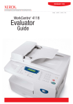
1
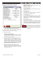
NMEA Data Combiner NDC-2-C Full User Manual Issue 2.36 Multiple talker interface for use with the NMEA 0183 standard for serial-data networking of marine electronic devices / instruments Personal computer (RS232) interface to NMEA 0183 Advanced NMEA 0183 filtering and priority levels to fully control the flow of NMEA 0183 data NMEA Data Combiner - NDC-2-C Contents Important Notices Notices Foreword Introduction General features 5 5 5 5 7 Software updates Technical features Connecting devices together 7 7 8 4 NMEA 0183 data input ports An NMEA 0183 data combined output port A PC compatible RS232 bi-directional port The basics The NMEA signals The different NMEA standards 7 7 7 8 8 8 Connections Connecting to NMEA 0183 devices 9 10 Other Connections 11 Actisense PC Software suites 12 Using the Control Centre 14 NMEA 0183 Inputs NMEA 0183 Output Connecting to a Personal Computer Connecting to the battery supply To install Actisense PC software To uninstall Actisense PC software Main window Initial hardware and software set-up Pull-down menus Port Configuration tab Why is there a need for Port Priorities? How to change port priorities and Baud rates Set-up Procedure Inclusion List configuration tab Why is there a need for Inclusion Lists? Is some NMEA data really unnecessary? How to change the Inclusion Lists Set-up procedure Flash Hardware window Advanced Features © 2006 Active Research Limited 10 10 11 11 12 13 14 15 16 17 17 17 19 20 20 20 20 22 23 23 Page 3 Actisense™ Test Hardware tab How to test the hardware’s Memory Control Centre Port Status window Hardware Port Status window Hardware Connection Status window Hardware Information window 24 24 25 26 26 27 Using the Flash Centre 28 Troubleshooting guide 31 Specifications System block diagram 33 34 Company Information 36 Main Window Pull-down menus Control Buttons and Text Displays Update Flash operation Diagnostic LED Control Centre Error Status window Notes: © 2006 Active Research Limited 28 28 29 30 31 32 35 Page 4 NMEA Data Combiner - NDC-2-C Important Notices Foreword The Actisense™ NMEA Data Combiner (NDC-2) is intended for use in a marine environment, primarily for below deck use. If the unit is to be used in a more severe environment, such use may be considered misuse under the seller’s warranty. Actisense™ recognises that instructions are often skipped, so we have aimed to write this document in an informative, yet direct manner that will aid the user. We have tried to cover all the points a typical user may need to know. Please read all sections before installing and using the Actisense™ NMEA Data Combiner product and any related software programs. The Actisense™ NMEA Data Combiner (NDC-2) has been certified to comply with the European directive for ElectroMagnetic Compatibility (EN60945), and is appropriately CE marked. Operation of the unit should be in conjunction with appropriate CE approved shielded connectors and cabling used in accordance with the CE directive EN60945. Any EMC related issues should be reported to Active Research immediately to allow the company to rectify or resolve EMC related problems in accordance with its obligations under EN60945. If the unit is connected such that compliance failure occurs beyond the company’s control, the company shall not be held responsible for compliance failure until suitable EMC guidelines for connection are seen to have been taken. Notices When using this document, keep the following in mind: The products described in this manual and the specifications thereof may be changed without prior notice. To obtain upto-date information and/or specifications, contact Active Research Limited or visit the Actisense™ website (www. actisense.com). Active Research Limited will not be liable for infringement of copyright, industrial property right, or other rights of a third party caused by the use of information or drawings described in this manual. All rights are reserved: The contents of this manual may not be transferred or copied without the express written permission of Active Research Limited. Active Research Limited will not be held responsible for any damage to the user that may result from accidents or any other reasons during operation of the user’s unit according to this document. The NDC-2 does not validate the NMEA data it receives in any way. Neither the NMEA sentence checksum, nor the data contained within the NMEA sentence is validated. Therefore, the electronic device(s) supplying the NDC2 with NMEA data retains the sole responsibility for the NMEA data’s validity. © 2006 Active Research Limited Introduction The Actisense™ NMEA Data Combiner (NDC-2) product developed out of the requirement to solve two fundamental problems with the existing marine industry NMEA 0183 communications standard. In theory, the NMEA 0183 standard allows any suitably designed marine electronic device to share its gathered information with any other device on a vessel. Unfortunately, there is one very large drawback with this standard - only one device on a connected network can actually send data (a single talker), with multiple devices (determined by the current limit of the sending unit) listening to that data (multiple listeners). If the vessel owner has an instrument that ideally requires the data output of two or more devices, for example a chart plotter, then the owner has no alternative but to settle on connecting only the most important device (that which supplies the most used information), normally that is the GPS unit. All other devices cannot be used. What happens if the owner prefers the vessels gyro compass heading output to that of the GPS, or requires that the current depth be displayed on the plotted chart to help avoid the possible case of running the vessel aground on a shifting sand bank? The NMEA 0183 standard cannot supply an answer to those questions as it can handle only one transmitting device. These two elementary problems can be solved simply and easily with the Actisense™ NMEA Data Combiner’s very flexible design approach. In this way all NMEA 0183 devices can share their information with each other (multiple talkers – multiple listeners). Alternately, if the vessel has two or more identical NMEA devices (e.g. GPS’s or depth sounders) the system solution could be to use the Actisense™ NMEA Autoswitch. Full information on the complete Actisense™ product range can be found on the Actisense™ website. Page 5 Actisense™ © 2006 Active Research Limited Page 6 NMEA Data Combiner - NDC-2-C General features Technical features 4 NMEA 0183 data input ports 16-bit high-speed micro-controller capable of 8 million instructions per second. Each NMEA 0183 input port has an “Inclusion List” that details all the NMEA sentences that are allowed to pass through the NMEA Data Combiner (NDC-2) and out on the combined NMEA 0183 output. This allows the NDC-2 to filter out all unwanted NMEA data and so reduce the loading on the NMEA combined output. Each NMEA 0183 input port also has a priority level. This is set by default to the logical order that matches the port numbers, i.e. port 1 has the highest priority and port 4 the lowest priority. An NMEA 0183 data combined output port This output combines the input data into one standard NMEA output. The inputs and the output have the same baud rate. This means that the output can only carry as much data as one of the inputs - therefore, the combined data from all four NMEA input channels could exceed the data carrying capacity of the NMEA output channel. Then the output channel is overloaded, new data of the same type as older data, still in the buffer, will overwrite the older sentence. This will only happen when the output load becomes too high, and ensures that the combiner cannot build up excess old data in the case where the output stream is fully loaded or overloaded. A PC compatible RS232 bi-directional port A PC can use the RS232 port to read all the NMEA data traversing through the NDC. This allows for the possibility of a “virtual cockpit” of instruments displaying all available data in any manner the user requires (available from a number of manufacturers). Flash ROM technology that supports automatic programming for quick and easy updates, 10,000 erase cycles and a 10-year Data Retention provides carefree user configuration. On-board memory store allows buffering of short term NMEA data, allowing the unit to smooth short-term peaks in the NMEA data flow. NMEA 0183 inputs are opto-isolated differential inputs to fully comply with the NMEA 0183 standard specification. This allows the inputs to work correctly with long cable runs and in a noisy environment. Typical operating voltage is 2.0V to 15V. The unit can withstand +/- 35V continuously, and +/- 40V transients. The opto-isolators can protect any upstream equipment (chart plotter / PC / radar etc.) from up to 2000V of common mode voltage difference. NMEA 0183 full-differential output driver. This can drive up to 15 typical NMEA 0183 device loads, with a 30mA (maximum) drive capability. The full-differential output ensures better quality communications and lower noise emissions on unshielded twisted pair cabling. Full specification RS232 interface ensures that any marine electronic device (or PC) that has an RS232 port receives all the input NMEA data, and can add its own NMEA data to the combined output. This connection also allows the unit to be updated via the free flash upgrade software (Flash Centre) that will be made available on the Actisense™ website if the NDC-2 software has been enhanced in any way. All the above ports are re-configurable and offer various Baud rates to improve device connection compatibility with other NMEA 0183 instruments. Low Power Consumption that is typically 100-110mA at 12 volts and 50-60mA at 24 volts. Software updates A diagnostic LED indicates the mode of operation of the NDC-2, if any faults have been detected, or the peak load currently on any one of the NMEA inputs. The NDC-2’s built-in software is held in “flash” memory, and can be quickly and easily updated / “flashed” by using the simple Windows (98/ME/NT/2000/XP) user interface program (Flash Centre), running on a connected PC. It is our policy to provide these updates free on our website, www.actisense.com, so that your combiner can become more sophisticated with time, and should there be any bugs reported in the software, they can be promptly fixed without the unit coming out of commission. This upgrade can be performed with the unit completely in-situ, via a PC connected to the RS232 port. © 2006 Active Research Limited Very tough Polycarbonate case is certified to IP66 (classified as “totally protected against dust and protection against low pressure jets of water from all directions”). Being Polycarbonate, it is also incredibly strong, offering a wide temperature range and superior protection to the electronics inside. The IP66 rating of the case is only limited by the sealing gasket strip, which can be enhanced by applying a suitable non-acid based marine sealant to the gasket after wiring and testing. This will allow use of the unit in areas where salt spray could enter, accidental immersion may occur, or in environments where maximum long-term reliability is paramount. Page 7 Actisense™ Connecting devices together The basics NMEA data is transmitted from an information source such as GPS, depth sounder, gyro compass etc. These data sending devices are called “Talkers”. Equipment receiving this information such as a chartplotter, radar or NMEA display is called a “Listener”. Unfortunately, only one Talker can be connected on to a single NMEA 0183 system at any one time. Two or more Talkers are simply not possible because they are not synchronised to each other, and will attempt to ‘talk’ at the same time (over each other), resulting in corruption of the NMEA data, and potentially in disaster if valuable data such as navigation information is lost or corrupted so that it is incorrect and/or misleading. Actisense™ produces a full range of products to solve all NMEA interfacing requirements. Please visit the Actisense™ website for full details on these and other Actisense™ interfacing, Depth sounding and Sonar products. The NMEA signals The NMEA 0183 system v2.0 and later uses a ”differential” signalling scheme, whereby two wires are used to transmit the NMEA data. These connections will be labelled as either NMEA “A” and “B“ or NMEA “+” and “-“ respectively, depending on the instrument and manufacturer. When connecting between different manufacturers, there can be some confusion, but it is simple and easy to remember: NMEA “A” connects to NMEA “+” and NMEA “B“ connects to NMEA “-“. The different NMEA standards The NMEA 0183 specification has slowly evolved over the years, so connecting one device to another is not always a straightforward matter. The earlier versions of NMEA 0183 (before v2.0, as detailed above), used slightly different connection methods and signal levels: the instruments had just one “NMEA” data line (‘Tx’ or ‘Out’), and used the ground as the other line - similar to the way a computer serial port works. This connection method is referred to as “single ended” instead of the “differential” method used by NMEA 0183 v2.0 devices. The data format is largely the same between both systems, with v2.0 adding some extra sentence strings, and removing older (redundant) sentence strings from the specification. The situation is further complicated, as many manufacturers still use the old (“single ended”) method of connection because it is cheaper to implement. So how can an older type NMEA device be connected to a newer type device? Care is needed – it is possible to damage or overload the output of a newer differential device if it is incorrectly connected to an older device. This is because the older devices used ground as the return, whereas the newer devices actually drive the NMEA “-/B” line between 5v and 0v. Thus, connecting this output to ground will result in high currents being drawn by the driver instrument, resulting in potential overheating and damage to the driver circuits. To connect a new type differential device to an old type single-ended system, connect the NMEA “+/A” output from the differential driver to the single-ended NMEA “Rx” or “In” input of the device. Leave the NMEA “-/B” output floating. Connect the ground line of the differential output device to the ground of the single-ended device. This provides the required data signal return current path. To connect an old type single-ended device to a new type differential device, connect the NMEA ”Tx” or “Out” output from the single-ended driver to the differential NMEA “+/A” input of the device. Connect the ground line of the single-ended output device to the NMEA “-/B” input of the differential device. This provides the data signal return current path. If the NMEA “-/B” input is left floating, then data corruption / errors may occur. Please refer to the Output Connections section for example of these connection methods. © 2006 Active Research Limited Page 8 NMEA Data Combiner - NDC-2-C Connections Figure 1 – All external connections The NMEA Data Combiner (NDC-2) has screw-terminal “Phoenix” type external connections for: 1. Four NMEA 0183 inputs. All NMEA 0183 inputs are of the differential optoisolated type and use the unique Actisense™ low current drain circuitry (2mA @ 2.0V) to conform in full with the NMEA 0183 marine electronic device network communication standard, and are flexible enough to interface to all fully and most partially compliant NMEA devices. 2. An NMEA (data combined) 0183 output. The NMEA 0183 data output comprises of three connections: ‘+’, ‘-‘ and ‘Ground’ and conforms in full to the NMEA 0183 standard. This allows the NDC to interface to various different devices that require any combination of these outputs. 3. An RS232 input/output. The bi-directional RS232 port is designed for direct connection to a computer (PC) or other marine device capable of interfacing to a standard RS232 port. Note: 1. To complete the NMEA 0183 standard all device interconnection NMEA cables used should meet the two-conductor, shielded, twisted pair configuration specification. The shield connection of these wires should be connected at the instrument end only to prevent ground loops. 2. Refer to the Specifications section for the full details on input/output specifications. 3. If the laptop / PC to be used with the NDC does not have an RS232 serial port available, the Actisense™ USB to RS232 adapter cable has been tried and tested to provide a compatible communications port. Please visit the Actisense™ website for full details on this, and other Actisense™ products. 4. Battery supply input (8 to 30 volts DC). © 2006 Active Research Limited Page 9 Actisense™ Connecting to NMEA 0183 devices ���� �������� � � ���� �������� � � ���� �������� � ���� �������� � � � �������� �� �������� � � � �� ���� ���������� � � ���� � ���������� ���� ���������� Figure 2 – NMEA 0183 connections NMEA 0183 Inputs The NMEA 0183 differential opto-isolated inputs are designed to handle a variety of NMEA 0183 device output specifications. Please determine (from device manufacturer’s information) if the device(s) required to be connected to the Actisense™ NDC-2 conforms in full to the NMEA 0183 network communication standard. If it does not, the flexible Actisense™ NDC-2 inputs should still be capable of interfacing with the device, though this is not guaranteed. The diagram above shows a typical installation with both fully compliant NMEA devices with differential inputs/ outputs, and non-differential output devices that output NMEA using the ground line as the “NMEA -” line. NMEA Talker devices 1, 2 and 4: These devices conform in full to the NMEA 0183 standard. Devices 1 and 4 share the same connection ID’s as the Actisense™ NDC, so connection is a simple matter of matching the ID’s (refer to Figure 2). Device 2 uses the RS485 convention connection ID’s. Simply connect ‘A‘ to ‘+/A‘ and ‘B’ to ‘ -/B’ (refer to Figure 2). NMEA Talker device 3: This device does not conform completely to the NMEA 0183 standard. However, by connecting ‘+‘ to ‘+/A‘ and its ‘G/Ground’ to the NDC “-/B” the NDC should be able to receive the NMEA data correctly. © 2006 Active Research Limited NMEA 0183 Output The NMEA 0183 buffered output is capable of driving up to 20 NMEA 0183 fully compliant listening devices, or a mixture of NMEA 0183 devices and a Personal Computer (PC) serial communication port. NMEA Listener device’s B and C: These devices conform in full to the NMEA 0183 standard and their connection ID’s match that of the NDC. Personal Computer: Whilst the RS232 port is designed for connection to a PC, the NMEA 0183 output can also be read by most PCs. Simply connect ‘+/A’ to ‘Rx’ and ’Gnd’ to ‘Ground’ on a standard 9-pin D-type (probably male) connector. NMEA Listener device A: This device does not conform in full to the NMEA 0183 standard. However, by connecting ‘+/A‘ to ‘Rx/In‘ and ‘Gnd’ to ‘G/Ground’ the device should be able to receive the NMEA data correctly, though this is not guaranteed. Note: 1. Wire colours are for guidance only. Page 10 NMEA Data Combiner - NDC-2-C Other Connections � �� �� ����� ������ � � ��������� ������������ Figure 3 – RS232 and Battery connections Connecting to a Personal Computer The RS232 port can be connected to a PC serial communications port using a cable conforming to the following specification: 1. A D-type female (socket) connector for the PC end of the cable. 2. A minimum of 3 cores are required in a shielded cable. Higher quality cable will naturally yield higher performance / higher Signal-to-Noise Ratio (SNR). Most typical cables have two twisted pairs inside. In this case, use one pair for the TX line and one for the RX line. Use the spare wire in each pair as ground, and connect the cable shield to ground only at the computer end. Connecting to the battery supply The Actisense™ NDC-2 should be wired to the vessel’s battery supply in the most direct manner possible, to minimize interference from other electronic devices. The cable used should be of sufficient gauge to handle the power requirements of the Actisense™ NDC-2 (refer to the Specifications sections). Note: 1. Wire colours are for guidance only. 3. The TX of the NDC-2 should be connected to the RX of the PC’s serial port (standard D-type, pin 2) and the NDC-2 RX should be connected to the TX of the PC’s serial port (pin 3). The NDC-2 GND should be connected to the PC’s serial port ground (pin 5). © 2006 Active Research Limited Page 11 Actisense™ Actisense PC Software suites The Actisense™ NMEA Data Combiner hardware can be configured, monitored and tested using its own dedicated Control Centre software suite. The Actisense™ NDC can be updated / upgraded using the latest Flash Centre software suite. This section provides a complete users guide to installing and uninstalling these two software suites. These programs are currently only available for Windows™ platforms (98/ME/NT/2000/XP), however, it has been proven possible to use the NDC Control Centre / Flash Centre on a Mac running Windows emulation software. To install Actisense PC software Replace the generic “<Product Name>” text below with the name of the actual software you are installing: “NDC Control Centre”, or “NDC Flash Centre”. 1. Download the latest version of the software from the Actisense™ website, or locate the files on the Actisense™ CD included with the NDC-2. 2. If a previous version of the software has already been installed, uninstall the previous version and delete the program directory before installing the new version. Refer to the To uninstall Actisense PC software section for full details. 3. If the program is contained within a zip file, extract the three files (‘<Product Name>.001,’ ‘<Product Name>.002’ and ‘setup.exe’) that are contained within the zip file using any available unzip program to a temporary directory (e.g. “C:\Temp”). Figure 4 – Install options 4. Double click on the ‘setup.exe’ program file and follow the on-screen instructions of the standard Windows™ install program. The install location can be change at this point, however, the default location is normally acceptable (refer to Figure 4 and 5). Once the install operation is complete, the temporary files and/or directory can be deleted. Keep the original zip file safe. Figure 5 – Installation complete 5. To start / run the program, use the Windows™ ‘Start’ menu and navigate to the installed program’s directory. There will be a program icon - double click on it (refer to Figure 6 and 7). Useful Tip: If you access the program regularly you can ‘copy and paste’ the program icon from the Windows™ ‘Start’ menu on to the desktop or the ‘Quick Launch’ short-cut bar to create a easy to access short-cut. © 2006 Active Research Limited Figure 6 & 7 – ‘Start’ menu short-cuts Page 12 NMEA Data Combiner - NDC-2-C To uninstall Actisense PC software Replace the generic “<Product Name>” text below with the name of the actual software you are installing: “NDC Control Centre”, or “NDC Flash Centre”. 1. If at any time you wish to remove the installed Actisense™ program, simply use the standard Windows™ ‘Start → All Programs → Actisense <Product Name> → Uninstall Actisense <Product Name>’ menu option to perform this operation (refer to Figure 7). Figure 8 – Uninstall confirmation 2. Alternatively, there is a very convenient uninstall icon included in the program’s folder (see Figure 6). 3. Once the uninstall operation has been requested, the confirmation box (Figure 8) will be displayed. Answer ‘Yes’ and the uninstall operation will be performed automatically. After successfully uninstalling the Actisense PC software, the uninstall completion box will appear (refer to Figure 9). Figure 9 – Uninstall complete 3. In addition, the program directory can also be deleted to completely remove the program. In this way all the program files will be uninstalled in a clean and complete manner. If however, you are going to install a new version after this uninstall, you can keep the program directory and the configuration file stored within it. In this way, all the user settings you had for the previous version will be immediately available with the new version. © 2006 Active Research Limited Page 13 Actisense™ Using the Control Centre The Actisense™ NMEA Data Combiner hardware can be configured, monitored and tested using its own dedicated Control Centre suite. This section provides a complete users guide to all the Control Centre’s features. This program is currently only available for Windows platforms (98/ME/NT/2000/XP), however, it has been proven possible to use the Control Centre on a Mac running Windows emulation software. Main window Figure 10 – Control Centre main window (after hardware detected) The Control Centre main window allows the user access to all the NDC hardware configuration, monitor and test features, and adjustment of the Control Centre’s actual appearance on screen. The Control Centre is capable of displaying a large array of data and information, and not all will be of interest to every user. Therefore, the user can easily select which information / status windows are of interest and are visible, and which are not (hidden). To meet the users specific requirements, any visible window can be repositioned on the screen by dragging it with the mouse. If a window is dropped (the left mouse button is released after the drag operation) close enough to an adjacent windows edge, it will snap to that windows edge. This allows for quick, easy and neat arrangement of the Control Centre’s windows. © 2006 Active Research Limited From the main window the user can select which NMEA sentence’s require filtering/blocking, what Baud rates the various inputs and outputs of the NDC need to be, and even start a hardware test operation. Selection of these options is possible by using the standard Windows menu system (‘Options’ menu) or via a tab system (behaving just like tabs in a filing cabinet). Full explanation of these features is detailed in the following sections. Any changes the user makes to the Control Centre’s appearance will be remembered for subsequent sessions, allowing the user to keep their favourite settings. Any new configuration settings must be downloaded to the NDC hardware before they can be remembered - this helps keep the Control Centre and NDC hardware in sync. The main window has an ‘Exit’ control button to close the Control Centre program. Refer to the menu File → Exit for full details on the operation of the exit request. Page 14 NMEA Data Combiner - NDC-2-C Initial hardware and software set-up Important information - please read. Figure 11 – Control Centre main window (before hardware detected) To access all the NDC-2 Control Centre configuration and test features, the Control Centre must first detect what type of NDC is connected. This allows the same Control Centre to be used for the NDC-1, NDC-2 and NDC-3 (as they have different configuration and test options). Before the NDC-2 hardware is detected by Control Centre, the main window will look like that in Figure 11 - with the sections ghosted out, and the ‘Inclusion List’ and ‘Test Hardware’ tabs hidden. Once detected, these disabled options will become active and the main window will look like that in Figure 10. To allow detection of the NDC hardware, perform the initial setup procedure: 1. Connect battery power to the NDC-2 and switch on the battery. The NDC-2’s LED will cycle through its standard start-up colours (‘red’, ‘amber’ and finally ‘green’). Refer to the Connecting to the battery supply section for more details. 2. Connect a standard RS232 cable from the PC to the NDC-2, via a 3-wire converter. Refer to the Connecting to a Personal Computer section. 3. Select the PC comm port number that the RS232 cable was plugged into from the options in the main windows ‘Comms’ menu. The Baud rate will default to 38400 Baud (the factory default), but will auto-Baud to the actual Baud rate if it has been changed. 4. The Rx and Tx ‘LED’s on the main window will flash to indicate that communication is in progress (between the Control Centre and the NDC-2 hardware). Once the hardware information has been received (and displayed), all the NDC-2 configuration and test options will be enabled. If for any reason the hardware detection operation does not happen as described, check all connections are made as required and are secure. © 2006 Active Research Limited Page 15 Actisense™ Pull-down menus The main window has five standard pull-down menus. File → Load / Save Configuration File: The Control Centre will automatically save its appearance and all other settings to file “ControlCentre.ini” so that the same settings can be used in subsequent sessions. Comms → Comm Port 1-8: Selects the PC communications port that the NDC hardware is attached to. The Baud rate will default to 38400 (the NDC hardware default). If the NDC is not using the default Baud rate, the Control Centre will try all possible Baud rates until the correct one is found (this will take up to 12 seconds). The offline option closes the communication port. If the user requires more than one configuration set up with unique Inclusion Lists and Port Configurations, then each set up can be saved and loaded back from this menu. This is very useful for standardising vessel installations. Note: Do not attempt to edit the “ControlCentre.ini” file by hand, as this can result in all the configuration settings being lost. File → Exit: Closes the Control Centre program. If the Inclusion Lists and/or the Port Configurations have been altered, but not yet transferred to the NDC hardware, the user will be asked to confirm the exit request (as all alterations will otherwise be lost when the program closes). Window → Control Centre Port Status: Displays the Control Centre’s port status window. Refer to Control Centre Port status window for full details. Window → NDC Hardware Port Status: Displays the NDC hardware’s port status window. Refer to the Hardware’s Port status window for full details. Window → NDC Hardware Connect Status: Displays the NDC hardware’s connection status window. Refer to the Hardware’s Connect Status window for full details. Options → Configure Inclusion Lists: Displays the Inclusion List configuration tab of the main window. Refer to the Inclusion List sub-section for full details on this feature. Options → Configure Ports: Displays the Port configuration tab of the main window. Refer to the Port configuration sub-section for full details on this feature. Options → Test Hardware: Displays the Test hardware tab of the main window. Refer to the Test hardware sub-section for full details on this advanced feature. © 2006 Active Research Limited Window → NDC Hardware Information: Displays the NDC hardware’s information window. Refer to the Hardware’s Information window for full details. Help → Control Centre Help: Currently unavailable (not selectable). Help → About Control Centre: Displays the Control Centre’s software version number and the Actisense™ contact information. Page 16 NMEA Data Combiner - NDC-2-C Port Configuration tab The Port configuration tab of the main window allows the user to select the priority and Baud rates of the NMEA and RS232 input ports of the NDC-2 hardware, and if the NMEA proprietary ARL (P-code) sentences are transmitted. Figure 12 – Port Configuration tab Why is there a need for Port Priorities? How to change port priorities and Baud rates Refer to ‘Why is there a need for Inclusion Lists?’ for a detailed explanation of the potential need to reduce the amount of data trying to be sent out of the combined output. If the Inclusion Lists cannot reduce the data rate below the 480 bytes/second maximum, then the port priority system comes into operation. The port configuration tab consists of a vertical port priority list, a Baud rate pull-down list for each NMEA/RS232 port, the P-code enable toggle control, and Get from Hardware, Reset to defaults and Send to Hardware buttons (refer to Figure 12). This system stipulates that all the data from the highest priority port will be passed through to the combined output. Then if any transmit capacity is left, the next lowest priority port’s data is transferred until either no data remains (the usual case), or the transmit capacity has reached its maximum of 480 bytes/second. If the rate of data in to the NDC hardware continues at this very high level, then eventually some sentences (from the lowest priority channel first) will have to be dropped. If however, the rate drops below the maximum, then the sentence data will be sent at the next opportunity. With the ‘Inclusion Lists’ set up correctly, data loss should be a very rare occurrence. © 2006 Active Research Limited Input Port Priority list: Click on two inputs in turn to change their positions in the priority list. The topmost item has the highest priority and the item at the bottom, the lowest. NMEA/RS232 Baud rate lists: Select the required Baud rate for the appropriate port(s). Please note that the NMEA 0183 specification restricts the Baud rate for NMEA data to 4800 Baud. Therefore, any input port that has an NMEA device attached to it that cannot modify its Baud rate must remain at 4800 Baud (otherwise no data will be received). However, some NMEA devices (e.g. GPS units) do allow for the Baud rate to be increased to 9600 Baud, or even 38400 Baud (Hi-Speed NMEA). Only in these cases should the Baud rate of the appropriate port be changed from 4800 Baud to match that of the attached device. Page 17 Actisense™ Extra ARL P-codes: Toggles the enable/disable state of the extra ARL Pcode sentences on the RS232 port. These P-codes are used by Control Centre to determine which NDC input supplied which piece of NMEA data. In this way, Control Centre can show what data came from channel 1, channel 2, etc. This ability is also open to any other PC program. For example, an NDC with 4 digital NMEA depth sounders connected to it could have the 4 individual depth values shown on a PC screen in representative positions (bow starboard, bow port, stern starboard and stern port). The RS232 Baud rate options are 4800, 9600, 19200, 38400, 57600 or 115200 Baud. It is important to note that setting the RS232 Baud rate to anything under 19200 Baud may reduce the bandwidth of this output below that of the total input bandwidth. This could result in random loss of NMEA sentences. Therefore, for normal operation, 38400 Baud is ideal, however, for exceptional requirements were the total input bandwidth is below 100%, any of the available Baud rates can be used. If in the unlikely event however, the RS232 port is connected to an electronic device (e.g. chart plotter) that cannot ignore the P-codes (as it should by default), then these P-codes can be disabled to aid compatibility. Note: As the Control Centre requires the extra Actisense P-code sentences to operate correctly, it will temporarily turn them on when it first connects to the NDC-2. When the Control Centre software is closed, the NDC-2 will revert back to the user-stored configuration settings, and the Pcode sentences will stop being transmitted (if configured by the user as disabled). Clone output mode: NMEA input 1 and the combined NMEA output are two sides of the same port, and therefore share the same Baud rate (with options of 4800, 9600, 19200 or 38400 Baud). NMEA input 2 has been specially designed as a hi-speed input (ideal for AIS transponders). Its Baud rate options are 4800, 9600, 19200, 38400, and the extra hi-speed option of 57600 Baud. Setting this input to 57600 Baud will however, restrict all other NMEA inputs to 4800 Baud - to help keep the total bandwidth to a manageable level. NMEA inputs 3 and 4 have the Baud rate options of 4800, 9600, 19200 and 38400 Baud. It is worth noting, that the NDC-2 receives and buffers all the NMEA 0183 sentences from all 5 inputs (4 NMEA 0183, and 1 RS232), and then as a totally independent operation, it re-sends the required NMEA 0183 sentences out its 2 outputs (1 NMEA 0183 and 1 RS232). As these two operations are independent, the Baud rates of all the inputs and outputs can also be independent, that is to say, different - the inputs and outputs can all have different Baud rates (with the except of Input 1). © 2006 Active Research Limited Toggles the enable/disable state of the data Clone output mode on the RS232 port. When the RS232 output port is in Clone output mode, the data output will be a clone, or copy, of the data output from the NMEA Combined output. That is to say, the data output will have been filtered just like the NMEA Combined output data is. This is useful if you need to supply an NMEA device with filtered NMEA data that will only accept RS232 signal levels on its input. When Clone output mode is disabled, the RS232 output will contain all data received on all 4 of the NMEA inputs. Delete duplicates: Toggles the enable/disable state of the useful Delete duplicates option. When enabled, any duplicate NMEA sentences found in the receive buffer that are deemed safe to delete older versions (duplicates) will be deleted. This intelligently reduces the output data when too much data is coming through the input channels. For example, if two depth sentences are in the buffer ready to be transmitted, there is normally no point in transmitting the older depth value, as the newer one has replaced all previous ones. However, for special systems that do not want this feature (and can guarantee that there will not be more than 100% total loading), this feature can now be disabled. Page 18 NMEA Data Combiner - NDC-2-C Get from hardware: Reads the current Port Configuration information, for all channels, from the connected NDC hardware. This will overwrite any current settings held by the Control Centre’s Port Configuration; if the current settings must be remembered, the File → Save Configuration file main window menu option should be used before requesting this operation. Reset: Returns all Port Configurations to the factory defaults – port priorities match channel numbers (port 1 has highest priority and port 4 has the lowest), NMEA Baud rates are set to 4800 Baud, RS232 Baud rate set to 38400 Baud and the extra ARL P-codes are enabled. Send to Hardware: Finalises the Port Configuration editing operation. If any alterations to the port configuration settings have occurred the Control Centre will now attempt to download the new settings to the attached Actisense™ NDC hardware. The Flash Hardware Control window will appear for the brief duration of the download (normally one to two seconds). Note: Pressing any of the threes buttons above will only affect the Port Configuration settings - all the Inclusion List settings will remain unaffected as they are controlled by their own independent set of buttons. Set-up Procedure 1. The RS232 communication port defaults to 38400 Baud - normally more than capable of transferring the received data of all four NMEA input ports. When connected to a Personal Computer there should not be any reason to change this Baud rate. However, if it is required to connect the NDC hardware to an RS232 compatible device that does not support the Baud rate of 38400, then the rate can be changed. Left click on the RS232 Port Baud rate control’s down arrow to display the list and then select the required Baud rate value. 2. The proprietary Extra ARL P-code sentences sent by the NDC hardware are completely benign and should be ignored by all other manufacturer devices. The Actisense™ software programs (Control Centre and Flash Centre) use these sentences to perform certain operations that enhance their control over the NDC hardware and are therefore important. There should not be any reason for requiring that these sentences be disabled. However, as Actisense™ believes in offering complete control over its products, it is possible to enable/disable these sentences by clicking on the Extra ARL P-codes control. © 2006 Active Research Limited 3. The RS232 output defaults to normal output mode that is, with the Clone output mode option disabled. If however, it is required to apply the NMEA filter settings to the RS232 data, enable this option. 4. As detailed above, the NMEA 0183 standard determines the Baud rate of 4800. If however, to make the NMEA input compatible with special devices that offer a different Baud rate, the rate can be changed by left clicking on the NMEA Port 1-4 pull-down lists. 5. To aid memory, it is normal to keep the port priorities in the same order as the port numbers - port 1 has highest priority and port 4 the lowest. However, if for some reason the port priorities require changing and it is inconvenient to alter the hardware connections, the port priorities can be changed using the Input Port priorities list. 6. If the NDC hardware has not been detected yet, the Control Centre will not allow the configuration transfer. If this happens check all cable connections, Control Centre communication settings (port number and Baud rate) and battery power to the NDC hardware (the diagnostic LED should be lit and either a ‘Green’ or ‘Amber’ colour). 7. When the Control Centre has detected the NDC hardware (the hardware information will be displayed in the NDC Hardware Information window), clicking the Send to Hardware control button will start a transfer of the new Port Configuration data to the hardware. This process can be monitored on the Flash Hardware Control and NDC Hardware Connection Status windows (normally for advanced users only). 8. The Flash Hardware Control window will display the success status of the transfer and then disappear. 9. If at any time you would like to return the Port Configuration settings back to their defaults, press the Reset to defaults control button followed by the Send to Hardware control button. Note: 1. The RS232 output is unaffected by the NMEA Port Priorities, and typically (when Clone output mode is disabled) retains all received data – as this port has a high enough transmit bandwidth/capacity to handle all NMEA data received. 2. Pressing any of the three control buttons on the Port Configuration Tab will only change / download / retrieve the port configuration values. The Inclusion List configurations will remain unchanged. Page 19 Actisense™ Inclusion List configuration tab The Inclusion List configuration tab of the main window allows the user to select which NMEA sentences are to be included in the onward data transmission from the NMEA Data Combiner. Each of the four NMEA input ports and the RS232 input port have their own Inclusion List, so that each can be tuned separately to match its connected device. Figure 13 – Inclusion List configuration tab Why is there a need for Inclusion Lists? Each of the four NMEA input ports can transfer anything up to 480 bytes of data per second, making a total of 1920 bytes/second. The data combined output of the NDC is also forced (by the NMEA 0183 standard) to send a maximum of 480 bytes/second. Therefore, there exists the distinct possibility that there could be more data to send out than is possible to achieve - thus, some data may require removal to balance this equation. The Actisense™ NDC-2 achieves this reduction in an intelligent manner with Inclusion Lists and Port Priorities. Is some NMEA data really unnecessary? Many NMEA instruments output a large number of sentences every period (usually 1-3 seconds), some of this data is of absolutely no use to the average boat owner, and just clogs up the NMEA network. Most GPS units are especially guilty of this and not all allow the user to reduce the number of unwanted sentences that are transmitted. Of those that do, the procedure can often be tricky and time consuming. The Actisense™ NDC-2 can filter the incoming NMEA data to remove any sentences deemed unnecessary. © 2006 Active Research Limited For example, most GPS units automatically output the ‘GSV’ sentences (normally 2 but could be as many as 4), which give details of all the satellites that are currently in view. All of this information is of no use to 99% of users, but this alone can use up to 5% of the available NMEA bandwidth/capacity. The Actisense™ NDC ‘Inclusion List’ default is to allow all sentences through. The user can modify these lists using a simple ‘tick-box’ panel from within the Control Centre. How to change the Inclusion Lists The Inclusion List configuration tab consists of two groups of sentence tick boxes, a box indicating the total number of selected sentences, an NMEA channel selection pulldown list, and Get from hardware, Reset to defaults and Send to Hardware control buttons (refer to Figure 13). Channel selection list: Determines which input channel (port) has its Inclusion List displayed for editing with the tick-box control’s in the main section to the left. Page 20 NMEA Data Combiner - NDC-2-C Main (left) tick-box area: Each NMEA 0183 sentence has its own individual tickbox, and is intended for the advanced user to fine tune the selection to exactly what is required (as this requires detailed knowledge of NMEA 0183 sentences). Sentence Groups (right) tick-box area: To make selection of NMEA 0183 sentence’s easier, all sentences of a particular type have been collected together, and is primarily intended for the novice user who does not know which sentences contain what information. The NMEA sentence collections are designed for quick list configuration; each collection influences all the NMEA sentence tick-boxes in the main (left) area that contain the selected information. The tick-box operation is straightforward: if the box is ticked, the corresponding NMEA sentence will appear on the combined NMEA output. Conversely, if the box is not ticked, that NMEA sentence will be blocked and not appear on the combined output. To completely disable the Inclusion List for a particular channel, click on the Clear all sentences button. The list status indicator will then change from the green List Enabled to red Pass all data. The Sentence Total box will also show that ‘0’ sentences are selected. Get from Hardware: Reads/retrieves the current Inclusion List information, for all channels, from the connected NDC hardware. This will overwrite any current settings held by the Control Centre Inclusion Lists; if the current settings must be remembered, the File → Save Configuration file main window menu option should be used before requesting this operation. Reset to defaults: Returns all channel Inclusion Lists to the factory default – all Inclusions Lists are disabled on all channels, which allows all sentences to be passed by default. Send to Hardware: Finalises the Inclusion List editing operation. If any alterations to the list have occurred, the Control Centre will now attempt to download the new settings to the attached Actisense™ NDC hardware. The Flash Hardware Control window will appear for the duration of the download and the details of the conversation can be viewed in the NDC Hardware Connection Status window (advanced users only). Note: Pressing any of the threes buttons above will only affect the Inclusion List settings - all Port Configuration settings will remain unaffected as they are controlled by their own independent set of buttons. Once disabled (and Pass all data displayed), all NMEA sentences will be passed to the NMEA combined output - no filtering will occur on this channel. This is only useful when trying to pass an NMEA sentence that is not available for selection in the Inclusion List and is not normally used. The buttons Clear all sentences and Set all sentences are useful to quickly reset or set all tick marks. This allows for quick configuration of the Inclusion List without having to click on every tick box. For example, if only a couple of sentences are required to be set, press the Clear all sentences button followed by selecting the couple of required sentence IDs. Sentence Total: The total number of NMEA sentences currently selected / enabled for the current channel / port is displayed in the bottom right corner. This is purely for user information and interest. © 2006 Active Research Limited Page 21 Actisense™ Set-up procedure 1. Remembering that the channel’s have a priority level (that only has a effect during very high loads), choose which device to connect to which channel. Place the most important device on channel 1 and so on. If the ‘Inclusion Lists’ are tuned to allow only the required data of each device through, then the port priorities will normally not come into operation (as the maximum output data rate will usually not be exceeded). 2. Starting with channel 1, place a tick next to all required NMEA sentences (using the individual tick boxes, the grouped tick boxes or a combination of both), by left clicking on the text or box with the mouse pointer. Note: 1. The RS232 output is unaffected by the NMEA Inclusion Lists and typically (when Clone output mode is disabled) retains all received NMEA data – as this port has a high enough transmit bandwidth/ capacity to handle all NMEA data received. 2. Pressing any of the three control buttons on the Inclusion List Tab will only change / download / retrieve the inclusion list configuration values. The Port configurations will remain unchanged. 3. Perform the same operation for any other channels that you intend to use. Use the Editing Channel selection list to change which channel is active - left click on the controls down arrow to display the list and then select the required channel number. Any combination of channels can be used – for example, in a twodevice set-up channel’s 1 and 3, or 2 and 3 etc. could be used. 4. If the NDC hardware has not been detected yet, the Control Centre will not allow the configuration transfer. If this happens check all cable connections, Control Centre communication settings (port number and Baud rate) and battery power to the NDC hardware (the diagnostic LED should be lit and either a ‘Green’ or ‘Amber’ colour). 5. When the Control Centre has detected the NDC hardware (the hardware information will be displayed in the NDC Hardware Information window), clicking the Send to Hardware button will start a transfer of the new Inclusion List data to the hardware. This process can be monitored on the Flash Hardware Control and NDC Hardware Connection Status windows (for advanced users only). 6. The Flash Hardware Control window will display the success status of the transfer and then disappear. 7. If at any time you would like to return the Inclusion List settings back to their defaults, press the Reset to defaults control button followed by the Send to Hardware control button. © 2006 Active Research Limited Page 22 NMEA Data Combiner - NDC-2-C Flash Hardware window The Flash Hardware window is displayed for the duration of the Inclusion List or Port Configuration update operation. In the case of updating the Inclusion List, a section of the Flash memory inside the NDC-2 hardware is first erased/cleared and then re-programmed with the new data. Figure 14 – Flash Hardware Control window Please note that during this updating process, it is vital that the Control Centre and NDC hardware are not interrupted. Therefore, the following precautions are suggested:– 1. Ensure there are no programs active/running on the PC other than the Control Centre. 2. Check that the RS232 cable between the PC and the NDC hardware is secure. 3. Confirm that the battery supply to the NDC hardware is secure. The Flash Hardware window consists of four LED’s that indicate the flash operations current status, a progress bar indicating percentage completed of the current stage, and a flash program counter that indicates how many times the NDC hardware’s Inclusion List has been re-programmed. The Success LED indicates the final outcome of the data transfer. If it does not light up green, the NDC Hardware Connection Status will indicate a more detailed cause and the process should be performed again. If the Flash hardware operation is interrupted, the Inclusion Lists or Port Configurations will become corrupted. The user should identify and remove the reason for the previous interruption before re-attempting to flash the hardware again (by pressing the Send to Hardware control button on the appropriate tab). Advanced Features The following windows and/or tabs will only be of interest to the advanced user, as they are not vital for the configuration of the NDC hardware. They do however, explain the useful diagnostic and monitoring features available. These advanced windows are hidden by default, and all novice users should advance past this section to the Using the Flash Centre section that follows. © 2006 Active Research Limited Page 23 Actisense™ Test Hardware tab The Test Hardware tab of the main window enables the advanced user to test the NDC-2 hardware’s RAM. This operation will only require completion when the hardware is suspected of being faulty and at the request of an Actisense™ support team member. Figure 15 – Test Hardware tab (after test has completed) How to test the hardware’s Memory The Test Hardware tab consists of four stage-status LED’s (Overlay, Connected, Running and Success), an LED and associated ‘Number of Errors’ text box for each of the memory tests, a progress bar indicating progress of current stage, and the Memory Test and Clear Results control buttons. Memory Test: Initiates the memory test - progress is indicated by the two test LED’s, and any accrued error count is displayed in the ‘Number of Errors’ box (refer to Figure 14 above). Once the memory test has completed, the NDC-2 hardware will be reset and restarted. © 2006 Active Research Limited Clear Results: Resets the Test Hardware settings to allow for another test to be started (if required). If the test indicates a RAM error and all connections to the NDC-2 hardware are proven correct, the user should consult the Troubleshooting guide. Page 24 NMEA Data Combiner - NDC-2-C Control Centre Port Status window The Control Centre status window displays all information relating to the communications port open between the Control Centre and the NDC-2 hardware. Figure 16 – Control Centre Port Status window This includes data received (from the NDC hardware) and data sent (to the NDC hardware), and the bytes-persecond transfer rate / buffer loading rate for both directions of the communications port. The current RS232 Baud rate being used for communication between the Control Centre and NDC hardware is displayed here for the user’s information. The Channel selection list allows the user to choose which channel’s NMEA data is displayed in the Received NMEA Data window. The Received NMEA Data window is valuable in monitoring the performance of the NDC hardware, and as a diagnostic tool for pinpointing: This enables each NDC input to be analysed and the NMEA data checked. For example, this is very useful in allowing the user to view an NMEA channel’s data and prove that the NMEA device connected to that NDC input is functioning correctly. This window should be the first port-of-call when trying to diagnose a problem with the NMEA system connected to the NDC-2. Contact a qualified marine electronic installer if you require hands-on help with understanding the NMEA 0183 data seen in this window. In addition, there is a very good source of NMEA information contained within the NMEA 0183 information sheet document available on the Actisense website™. © 2006 Active Research Limited • A port overload condition - this is when the maximum data transfer rate of a port is exceeded, and data is being dropped/deleted randomly as a result. • A data corruption condition - this is either when the signal level of NMEA 0183 data being received is marginal and/or suffering from interference, or when interference is occurring between the NDC-2 and the computer running Control Centre. • When all data is being processed as required. Page 25 Actisense™ Hardware Port Status window Hardware Connection Status window Figure 17 – Hardware Port Status window Figure 18 – Hardware Connection Status window The NDC hardware status window, like the Control Centre Port Status window, displays bytes-per-second transfer rates and buffer loading rates for a number of ports. However, these values relate to the ports on the NDC hardware – the four NMEA input ports, NMEA combined output port and the RS232 input/output port. The NDC hardware connection status window displays all information related to the connection status between the Control Centre and the NDC hardware. This includes all handshaking and data transfer information required for flash programming the NDC hardware during Inclusion List and Port configuration data updates. This data is also valuable in monitoring the performance of the NDC hardware, and as a diagnostic tool for pinpointing an overload condition (refer to Control Centre Port Status window for more details). Reset: Resets the connection status messages currently displayed, clearing the window. Note: The Bytes Filtered and Bytes Dropped indicators are currently only available when the Control Centre is being used with an Actisense™ NDC-3 or NDC-3-USB. © 2006 Active Research Limited Page 26 NMEA Data Combiner - NDC-2-C Hardware Information window 4. NMEA 2000 version: Currently supported NMEA 2000 version. Not applicable to the NDC-2-C 5. Total operating time: The total time that the NDC hardware has been operating since new. 6. ARL model code: The Manufacturer’s Model ID. Model “0” determines the hardware as an NDC-2 module. 7. ARL hardware version: The Manufacturer’s hardware revision number. Version “1.02”, in combination with the Model ID “0” determines that this NDC is actually an NDC-2-C product variant. 8. Flash program counters: The counters for each sector of the hardware’s Flash ROM. These counters keep a tally of how many times each sector has been reprogrammed. The current microcontroller is rated for 10,000 cycles per sector. Reset: Figure 19 – Hardware Information window Resets the hardware information displayed and requests the current information from the NDC hardware (thus refreshing the information). The NDC hardware information window displays the information received from the NDC hardware. This information Includes:1. Hardware Serial ID number: The unique serial identification number given to each Actisense product. This number is used to identify each NDC-2 unit in our records. 2. Bootloader & Main (software) program version: Version numbers of the bootloader and Main application software programs. If the Main program’s version number is older (less than) that of the currently available Flash Centre, the latest Flash Centre should be downloaded from the Actisense™ website and the NDC module updated. 3. Bootloader & Main program date and time: Dates and times that the bootloader and Main Application programs where updated / ‘flashed’ into the hardware’s memory. © 2006 Active Research Limited Page 27 Actisense™ Using the Flash Centre The Actisense™ NDC-2 firmware can be easily and quickly updated using the Actisense™ Flash Centre. The main window has a simple look, as the flash update process has been completely automated for a trouble-free operation. Main Window File → Exit: Closes the Flash Centre program. Figure 20 – Flash Centre main window This program is currently only available for Windows platforms (98/ME/NT/2000/XP), however, it has been proven possible to use the Flash Centre on a Mac running Windows emulation software. The Flash Centre main window consists of the Hardware Connection Status text box (identical to the Control Centre’s Hardware Connection Status window), Current Version and New Version text boxes, and the Update Flash and Exit control buttons. The NDC hardware should be connected to the PC communications port and a battery supply as per the instructions in the Connecting to a Personal Computer section and Figure 3 (RS232 and Battery connections). Comms → Comm Port 1-5: Selects the PC communications port that the NDC hardware is attached to (via the extension cable). Comms → Baud rate 4800-115200: Selects the PC communications port Baud rate to match that of the NDC hardware attached to the port. The Baud rate will default to 38400 (the NDC hardware default). If the NDC is using a different Baud rate, the Flash Centre will automatically match the NDC hardware’s Baud rate - if the ‘Extra ARL P-Codes’ option is enabled. Pull-down menus The main window has three standard pull-down menus:Help → Flash Centre Help: Currently unavailable (not selected) Help → About Flash Centre: Displays the Flash Centre’s software version number and the Actisense™ contact information. © 2006 Active Research Limited Page 28 NMEA Data Combiner - NDC-2-C Control Buttons and Text Displays Connection Status: Displays all handshaking and data transfer information required for flash programming the NDC hardware during the firmware update. If however, the diagnostic LED is lit and ‘Red’ in colour AND there was an interruption to a previous attempt to update the hardware’s firmware with the Flash Centre, reset the NDC hardware (by removing the battery power, waiting 5 seconds and then reconnecting the battery power), and press the Continue button. Current Version: Displays the version of firmware currently resident in the NDC hardware’s Flash ROM. This is received from the NDC hardware when Flash Centre detects the NDC hardware’s presence. New Version: Displays the version of firmware that the Flash Centre can upgrade the NDC hardware to. This number must be greater than the Current Version for an update to be required (and allowed) by the Flash Centre. If the New Version is older or equal to the Current Version, then the Flash Centre will block all attempts to update the NDC hardware – as there is nothing to be gained, and perhaps a reduction in functionality and performance. Figure 21 – “Hardware already up to date” message Update Flash: Initiates the flash update of the NDC hardware. If the NDC hardware has not been detected (normally due to a previous problem), the Flash Centre requests a confirmation from the user. Figure 22 – “Hardware not detected” message The final message displayed (or only message if there are no problems) asks the user if they require that the NDC hardware’s Inclusion List be reset back to factory defaults, or kept as is. The normal answer is No, keep the current settings, but if the user would like to take this opportunity to reset the Inclusion Lists to defaults, then select Yes. Figure 23 – “Update Hardware’s Inclusion List” message The Inclusion Lists can also be reset back to the factory defaults by using the Control Centre (refer to How to change the Inclusion Lists section). As the message in Figure 22 explains, if the diagnostic LED is lit and ‘Green’ in colour, check all cable connections, Flash Centre communication settings (port number and Baud rate) and battery power to the NDC hardware. Press the Cancel button. Once the problem has been found the Current Version box will display the hardware’s version number and the Update Flash button can be pressed. © 2006 Active Research Limited Page 29 Actisense™ Update Flash operation Once started, the Flash Hardware Control window will be displayed (refer to Figure 24) and show the progress indicated by the four-stage status LED’s and the progress bar. The Hardware Information Status box will display the relevant information during this process. The user is not required to interact with the process during the update. Once complete, the NDC hardware will be automatically reset and the new Current Version number will be displayed (which will now be the same as New Version number). Refer to Figure 25 for details. Figure 25 – Flash Centre main window (complete) Figure 24 – Flash Hardware Control window Exit: Once the flash process is complete (indicated in the text box and on the progress bar), the user can exit from the Flash Centre by pressing the ‘Exit’ control button (or using the File → Exit menu option). The ‘Exit’ option (or any control on the main window) is not active during the flash process. Please note that during this updating process, it is vital that the Control Centre and NDC hardware are not interrupted. Therefore, the following precautions are suggested:– 1. Ensure there are no programs active/running on the PC other than the Flash Centre. 2. Check that the RS232 cable between the PC and the NDC hardware is secure. 3. Confirm that the battery supply to the NDC hardware is secure. If the Flash Centre operation is interrupted, the NDC‘s firmware will become corrupted. The user should identify and remove the reason for the previous interruption, before re-attempting to flash the NDC hardware again. This time the “Hardware not detected” message (Figure 22) will be displayed and the on-screen messages must be followed carefully to perform the recovery update operation. © 2006 Active Research Limited Page 30 NMEA Data Combiner - NDC-2-C Troubleshooting guide This guide will concentrate on all relevant troubleshooting issues above simple cable connection faults. Therefore, the cables between the NDC-2 hardware and any other device should be checked as a matter of course, before continuing with this guide. Diagnostic LED The NDC-2 hardware supports a tricolour diagnostic LED that indicates the current operating mode of the hardware, or if an error has been detected during the self-test initiation process. Table 1 details what each LED colour represents and if any user interaction is required. LED Colour / Flash Count Mode / Error condition Required user response Normal operation modes The sequence below indicates a successful power-up of the NDC-2 and the commencement of data combining. Red, No flashing Start-up mode, No error No response required. A normal operation mode that should last for no more than 1.5 seconds. Any longer indicates an error with the main program. Red, No flashing Flash updating mode, No error No response required. LED will stay red for the duration of the flash update operation (using Flash Centre). Once operation complete, NDC hardware will be automatically reset. Amber, No flashing Initialise and self-test mode, No error No response required. A normal operation mode that follows after the Start-up mode and should last for approximately one second. No response required. A normal operation mode that follows the Initialise and self-test mode. Indicates that no error was detected during the self-test operation. Green, No flashing Normal and no data mode, No error Green, Flashing (1-10 per second) Normal and data Rx mode, No error No response required. A normal operation mode that indicates that data is currently being received (on at least one channel) by the NDC-2 hardware. Flash rate proportional to Rx rate. Error conditions If the error persists the NDC-2 unit should be returned to Actisense™ (refer to the Contact Information section). Also indicates that no data is currently being received by the NDC-2 hardware. Amber, Flashing (Once every 4 seconds) Error trap mode, EEPROM memory error An error with the EEPROM memory has been detected during the self-test mode. Amber, Flashing (Twice every 4 seconds) Error trap mode, RAM memory error An error with the RAM memory has been detected during the self-test mode. Reset the NDC-2 hardware. Amber, Flashing (Thrice every 4 seconds) Error trap mode, external UART memory error An error with the external UART has been detected during the self-test mode. Reset the NDC-2 hardware. Reset the NDC-2 hardware. Table 1 – Diagnostic LED colours © 2006 Active Research Limited Page 31 Actisense™ Control Centre Error Status window The Control Centre will display any error information received from the NDC-2 hardware in a window like those in Figure 27. If this window is displayed, follow the message instructions carefully and then if the fault persists, contact Actisense™ (refer to the Contact Information section). Figure 27 – Control Centre Error Status windows © 2006 Active Research Limited Page 32 NMEA Data Combiner - NDC-2-C Specifications Parameter Conditions Min. Max. Unit 8 30 V Supply voltage = 12v 55 75 mA Supply voltage = 24v 30 40 mA -15.0 0.5 V 4.0 15.0 V 2.0 30 mA 1.8 2.0 V 0.0 0.5 V 4.8 5.2 V - 20 mA - 35 mA 4800 38400 bits/sec 1.0 100 ms -15 +15 V LOW 0.8 1.2 V HIGH 1.7 2.8 V Output voltage swing Loaded with 3κΩ to Ground ±5 ±9 V Output resistance Output short circuit current (Infinite duration) Baud rate (RS232 Vout = ±2V) 300 Supply Supply voltage Supply current (see note 1) NMEA Input voltage between +/Input current Differential input voltage Output voltage between +/- and ground (see note 2) Output current (see note 2) Logical ‘1’/stop bit Logical ‘0’/start bit Maximum is under +35v overload condition Required level for NMEA to be detected Logical ‘1’/stop bit At maximum load, drive voltage reduces to 2V Output short circuit current. Baud rate - fixed (see note 3) Data propagation delay RS232 Input voltage range Input voltage threshold Data propagation delay Ohms ±18 mA 19200 115200 bits/sec 1.0 100 ms -20 +70 °C General Ambient temperature Table 2 – NDC-2 specifications All specifications are taken with reference to an ambient temperature (TA) of +25°C. Note: 1. Current consumption measured under no-load conditions 2. NMEA output is RS485 compatible. 3. NMEA 0183 requires 4800 Baud (factory default). However, to maximise compatibility with other devices and HiSpeed NMEA 0183, the baud rate is selectable between values shown. NMEA input 2 also has an extra Hi-speed option of 57600 Baud to allow use with AIS transponders (however, this option will force all other NMEA 0183 inputs to 4800 Baud to control the total bandwidth). © 2006 Active Research Limited Page 33 Actisense™ System block diagram Details the flow of data through the NMEA Data Combiner’s system. NMEA Input Circuitry Port 1 Inclusion List Channel 1 NMEA Input Circuitry Port 2 Inclusion List Channel 2 NMEA Input Circuitry Port 3 Inclusion List Channel 3 NMEA Input Circuitry Port 4 Inclusion List Channel 4 RS232 Input Circuitry Inclusion List RS-232 NMEA Port Priority Controller NMEA Output Circuitry (Combined) RS-232 Port Controller RS-232 Output Circuitry Figure 28 – NMEA Data Combiner signal flow block diagram © 2006 Active Research Limited Page 34 NMEA Data Combiner - NDC-2-C Notes: NMEA Input (1-4) NMEA Device connected Baud rate RS232 Input & RS232 Output NMEA Device connected Baud rate NMEA Combined Output NMEA Device connected Baud rate © 2006 Active Research Limited Page 35 Actisense™ Company Information Active Research Limited 5, Wessex Trade Centre Ringwood Road Poole Dorset UK BH12 3PF Telephone: Fax: 01202 746682 (International : +44 1202 746682) 01202 746683 (International : +44 1202 746683) Actisense™ on the Web: For advice, support and product details E-mail: Website: [email protected] www.actisense.com Active Research on the Web: For specialist consultancy and customisation E-mail: Website: [email protected] www.activer.com © 2006 Active Research Limited Page 36