1
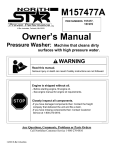
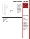
Model CEPS-850
Installation Instructions
& User Manual
UL
®
UL924 LISTED
EMERGENCY LIGHTING
EQUIPMENT
73PK
IMPORTANT SAFEGUARDS:
READ AND FOLLOW ALL SAFETY INSTRUCTIONS
When using electrical equipment, basic safety precautions
should always be followed, including the following:
1. Do not install outdoors.
2. Do not install near gas or electric heaters.
3. Mount CEPS-850 securely and in locations and at heights where it will not be readily subjected
to tampering by unauthorized personnel.
4. Do not use this equipment for other than its intended use.
5. All installation and servicing of this equpiment must be performed by qualified personnel.
6. The use of accessory equipment not specified or recommended by LVS, Inc. may cause
unsafe conditions and may void the warranty.
7. Use caution when servicing batteries. Battery acid can cause burns to skin and eyes. If acid is
spilled on skin or in the eyes, flush with fresh water and seek medical attention immediately.
8. Make sure all connections are in accordance with NEC and local regulations.
9. Check AC Voltage rating on equipment label. Do not connect to any other voltage.
10. An unswitched AC power source is required (120 VAC 240VAC 277VAC).
11. Do not use this product for other than intended use.
12. To reduce risk of electric shock, disconnect dedicated input breaker and all fuses before servicing.
13. Do not attempt to service sealed components with the exception of standard battery replacements.
SAVE THESE INSTRUCTIONS
LVS, Inc. 2555 Nicholson Street, San Leandro, CA 94577-4216
Phone: 510-352-9600
1-800-982-4587 Fax: 510-352-6707
www.lvscontrols.com
Unit Specifications
Input 120V,240V,277V 50/60 Hz, 5 W Power Consumption when batteries are fully charged.
Output 120V,240V,277V 50/60Hz 850 W Pure Sine
Wave at 7.1 Amp for full 90 minutes
10 Amp Input Fuse
10 Amp Output Fuse
Automatic Output Voltage Tracking maintains output
voltage at full load at 120V ± 1.5% for a full 90
minutes emergency operation.
Operates
fluorescents,
dimmable
fluorescent
ballasts, CFL, LED, halogen and incandescent loads.
Distortion: Less than ± 2%
EMI in compliance with FCC Class A Regulation
Test switch to simulate utility power loss.
Thermostat Controlled Silent Cooling Fan
Power Factor: Unity using incandescent loads.
0.9 leading to 0.9 lagging depending on load.
1.5 seconds transfer time to protect against
momentary ON/OFF voltage surges caused by
power line hitting wet pavement or other power
lines during a storm.
Operating Temperature: 40°F to 100°F
Frequency Regulation: ± 3%
Automatic low voltage battery disconnect
Only Annual Testing is Required.
Efficiency: 93-99% at 850 Watt Load
Sealed Lead Acid batteries provide long life
and are maintenance free.
GFCI Protection
Safety & Protection
Safe, momentary overload: Up to 1500 W, for safe operation when using incandescent loads.
Audible Warning Buzzer: Audible alert supervises Utility Power and Battery Charger.
Can be disconnected by cutting yellow jumper protruding from control enclosure. Be sure to
reconnect when testing is completed.
TEMPORARY STORAGE INSTRUCTIONS:
For temporary storage of CEPS-850 system and batteries prior to installation select a clean, cool, dry location with
normal ventilation suitible for human habitation and level floors. DO NOT store system or batteries in a sealed room
or container. Ensure that floor is cabable of bearing load.
Do not store batteries for more than 90- days without charging. Doing so will cause irreversible damage to battery
cells and void battery warranty. Ensure batteries are stored at temperatures within the following range: 40ºF to 100ºF.
3 Year Warranty
6 Year Pro-Rata Battery Warranty
LVS Inc., warrants to the original purchaser/user for the published warranty period from the date of shipment that should LVS
instruments or equipment prove defective by reason of improper workmanship or material, LVS will repair or replace the same
equipment without charge. This warranty does not cover defects or malfunctions arising from improper installation, operation or
repair, or neglect, accident or abuse. LVS will honor its warranty provided the equipment has not been physically damaged or
improperly installed or connected. To obtain warranty/repair, the defective product should be shipped freight prepaid within the
warranty period to the address below. To the extent permitted by applicable law, all warranties extending beyond repair or
replacement as described above are disclaimed, including the implied warranties of merchantability and fitness for a particular
purpose. Where applicable law prohibits disclaimers or the implied warranties of merchantability and fitness; those warranties
are limited to 12 months from date of shipment. LVS does provide a 90 day money back guarantee if equipment does not
perform in accordance with LVS published specifications. The liability of LVS and its agents under all warranties is limited to
repair and replacement as described herein, and under no circumstances shall there be liability for any other kind of loss,
damage, or labor, either consequential or for injury to person or property or otherwise.
2
Batteries are supplied on a pro-rata basis for six years, provided that the product
has been properly installed in the correct surroundings.
Panel Location
1. Panel should be installed in a ventilated indoor location and not subjected to temperatures above 100 °F
(37.8 °C) nor below 40 °F (4.5 °C) and at an altitude of less than 10,000 feet for optimum performance.
2. When the panel is installed on the wall, the wall must have sufficient strength to support a weight of 200
pounds and a minimum of 4 screws (#10) should be securely fastened in wood or concrete with plastic
inserts to secure the panel.
3. Remove 2 knockouts from the top of the panel.
4. Install utility input conduit and wire from a dedicated circuit breaker, 120VAC 60 Hz, 240VAC 50Hz, or
277VAC 60 Hz such as provided for a
fire alarm or security system.
5. Install emergency output conduit and wire for appropriate output voltage.
6. When you receive the panel, it will already have controls installed and indicating LED’s and test switch
should be visible on the outside of the panel. The panel has a protective cardboard cover during shipment,
which should be removed after the panel has been securely mounted.
Battery Installation
1. Remove batteries from shipping boxes and check for enclosure and terminal damage.
2. Batteries should have numbers 1 through 8 on them and already have 3” jumpers installed.
Battery 2
Battery 3
Battery 5
Battery 8
(+) 3” Red
(+) 3” Red
(+) 3” Red
(+) 3” Red
(-)
(-)
(-)
(-)
3” Black
3” Black
3” Black
3” Black
Battery 1
Battery 4
Battery 6
Battery 7
(+)
(+)
(+)
(+)
3” Yellow
3” Yellow
8” Yellow
3” Yellow
(-)
(-)
(-)
(-)
3” Black
3” Black
3” Black
3” Black
3. Home runs are numbered according to battery numbers and are already installed in the panel. Leave
protective sleeves on wires till ready to make final connections. Always make connections one at a time.
4. Follow “BATTERY INSTALLATION” label on inside of panel door for instructions on wiring batteries.
NOTE: Only wires of the same color should ever be connected using a wire nut.
(Black to Black, Red to Red, Yellow to Yellow).
5. Complete the following battery voltage tests after all batteries are installed.
Measure DC voltage between the following terminals, all readings should be between 22V and 28V.
Battery #1 (-) & Battery #2 (+)
Battery #3 (-) & Battery #6 (+)
Battery #4 (-) & Battery #5 (+)
Battery #7 (-) & Battery #8 (+)
6. Ensure that all connections have been made in a workman-like manner, and that panel door can close.
3
AC Input/Output Wiring Instructions
The CEPS-850 must be installed by a qualified electrician in accordance with local, state, and NEC codes. AC &
DC Voltages are hazerdous and care should be taken to follow all instructions. Prior to wiring AC connections,
disconnect AC Input feed at relevant branch circuit breaker(s). Always wear appropriate clothing when handling
batteries and equipment, and use insulated tools.
1)
2)
3)
4)
Remove all (3) fuses from control box, mounted on cover.
Disconnect all snap-in connectors on the right side of the 3rd shelf.
Ensure that knockouts on top of panel have been removed and conduits have been installed.
Bring AC Input conductors and AC Output Conductors through the appropriate conduits. Per
NEC, emergency output circuit should be installed in a dedicated conduit.
5) Connect AC Output conductors to wires labelled “Output” (red and white with red stripe)
6) Connect AC Input conductors to wires labelled “Utility Input” (black & white)
7) Connect grounds for AC Input & AC Output to stripped ends of grounding wires provided.
8) Plug 2 Pole connector labelled “CHARGER” together.
9) Plug 4 Pole connectors labelled “INVERTER -” together.
10) Plug 4 Pole connectors labelled “INVERTER +” together.
11) Ensure that cabinet is securely fastened to wall and that no wires are loose or disconnected.
12) Ensure proper grounding of all system components and enclosures.
13) Ensure all final connections have been made in a workman-like manner, so that low voltage
and line voltage connections do not touch, per UL regulations.
YOU MAY NOW CONSULT STARTUP PROCEDURE DISPLAYED ON PANEL DOOR.
If CEPS-850 output does not match specifications, or is stuck in emergency
mode (buzzer on) please consult the following troubleshooting guide:
Test #1: Remove 3 fuses mounted in control box, and check continuity. Replace with 10A 250V fuses if necessary. Re-insert all fuses.
Test #2: Observe indicator lights on inverter mounted in top shelf of panel. If any LED’s are flashing or are RED
in color, remove inverter from top shelf of panel, and press switch mounted on side of inverter, next to GFCI outlet.
All LED’s should become green or yellow, if not, consult LVS, Inc.
Test #3: Allow 72 hours for batteries to charge and run battery voltage test described on page 3. If voltage is still
irregular, consult LVS, Inc. regarding battery wiring and replacement.
Test #4: Check all wire nuts for good electrical connections and ensure that no bare conductors are exposed.
Also, ensure that all plug-in connectors are firmly inserted and locked. If replacing loose connections, first disconnect 3 plug-in connectors.
4