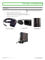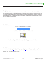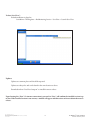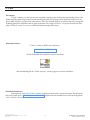
1
Cx Monitor™ User Manual
March 25, 2015
Rx Monitoring Services, Inc.
22A Eastman Ave
Bedford, NH 03110
Tel: 603-666-6606
Fax: 603-666-0509
[email protected]
http://www.rxms.com
©2013 Rx Monitoring Services, Inc.
Specifications are subject to change without notice.
Please refer to http://www.rxms.com/downloads/instructions/Cx_Monitor_User_Manual.pdf
For current release
1
Cx Monitor™ User Manual
Revised: March 25, 2015
Statements, Notices and Liability information
FCC Part 15 Class B
This equipment has been tested and found to comply with the limits for a Class B digital device, pursuant to part 15 of
the FCC Rules. These limits are designed to provide reasonable protection against interference in a residential installation.
This equipment generates, uses, and can radiate radio frequency energy and, if not installed and used in accordance with
the instructions, may cause harmful interference to radio communications. However, there is no guarantee that interference will not occur in a particular installation.
If this equipment does cause harmful interference to radio or television reception, which can be determined by turning
the equipment off and on, the user is encouraged to try to correct the interference by one or more of the following measures:
• Reorient or relocate the receiving antenna.
• Increase the separation between the equipment and receiver.
• Connect the affected equipment and the panel receiver to separate outlets, on different branch circuits.
• Consult the dealer or an experienced radio/TV technician for help.
Statement of Faultlessness:
The information in this manual has been reviewed for accuracy at the time of writing. No responsibility can be assumed
by Rx Monitoring Services Inc. for inaccuracy or changes that have taken place since production. The “Cx Monitor User
Manual” is for informational purposes only and is subject to change without notice.
Liability:
Rx MONITORING SERVICES, Inc. SHALL NOT BE LIABLE FOR ANY (A) SPECIAL, INDIRECT, INCIDENTAL, PUNITIVE, OR CONSEQUENTIAL DAMAGES, INCLUDING LOSS OF PROFITS, ARISING FROM OR RELATED TO A
BREACH OF THIS AGREEMENT OR ANY ORDER OR THE OPERATION OR USE OF THE MONITORING EQUIPMENT INCLUDING SUCH DAMAGES, WITHOUT LIMITATION, AS DAMAGES ARISING FROM LOSS OF DATA OR
PROGRAMMING, LOSS OF REVENUE OR PROFITS, FAILURE TO REALIZE SAVINGS OR OTHER BENEFITS, DAMAGE TO EQUIPMENT, AND CLAIMS AGAINST CUSTOMER BY ANY THIRD PERSON, EVEN IF RXMS HAS BEEN
ADVISED OF THE POSSIBILITY OF SUCH DAMAGES; (B) DAMAGES (REGARDLESS OF THEIR NATURE) FOR ANY
DELAY OR FAILURE BY RXMS TO PERFORM ITS OBLIGATIONS UNDER THIS AGREEMENT DUE TO ANY CAUSE
BEYOND RXMS’S REASONABLE CONTROL; OR (C) CLAIMS MADE A SUBJECT OF A LEGAL PROCEEDING
AGAINST RXMS MORE THAN TWO YEARS AFTER ANY SUCH CAUSE OF ACTION FIRST AROSE.
Copyright:
© 2013, Rx Monitoring Services Inc.
ALL RIGHTS RESERVED. This document contains material protected under International and Federal Copyright Laws and Treaties. Any
unauthorized reprint or use of this material is prohibited. No part of this manual may be reproduced or transmitted in any form or by any means,
electronic or mechanical, including photocopying, recording, or by any information storage and retrieval system without express written permission from Rx Monitoring Services Inc.
©2013 Rx Monitoring Services, Inc.
Specifications are subject to change without notice.
Please refer to http://www.rxms.com/downloads/instructions/Cx_Monitor_User_Manual.pdf
For current release
2
Cx Monitor™ User Manual
Revised: March 25, 2015
Safety Information
Definitions
• WARNING
This statement is to reinforce the practice of certain conditions may cause physical bodily harm or loss of life.
• CAUTION
This statement is to reinforce the practice of certain conditions may cause physical damage to the Cx Monitor,
accessories, equipment or property.
• NOTE
General information for simplifying the user experience.
Abbreviations
CT’s : Rope Probes : Cx : Monitor :
Current Transducers
Rogowski coil current transducers
Power Monitor
Power Monitor (Cx)
Wireless Probes:
EWE:
Site:
Wireless add-on’s for power monitor
External Wireless Extensions
Cx Monitor data set.
Symbols
The following are (IEC) symbols are used on this document or on the power monitor, and their definitions.
This symbol indicates that caution is necessary when operating the
device or control close to where the symbol is placed, or to indicate
that the current situation needs operator awareness or operator
action in order to avoid undesirable consequences.
This symbol indicates AC or DC voltage or current
This symbol indicates high voltage. It calls your attention to
items or operations that could be dangerous to you and other
persons operation this equipment.
Read the message and follow the instructions carefully.
This symbol indicates DC only voltage or current
This symbol indicates safety ground conductor.
This symbol indicates AC only voltage or current
This symbol indicates earth ground conductor.
©2013 Rx Monitoring Services, Inc.
Specifications are subject to change without notice.
Please refer to http://www.rxms.com/downloads/instructions/Cx_Monitor_User_Manual.pdf
For current release
3
Cx Monitor™ User Manual
Revised: March 25, 2015
WARNING
To avoid electrical shock or fire:
Review the entire manual before using the Power Monitor and its accessories and observe all warnings and cautions.
•
Before using the power monitor inspect wireless probes, voltage probes, current probes, leads and accessories for mechanical damage or broken plastic and call Rx Monitoring Services Inc. for replacements.
•
Wear proper Personal Protective Equipment, including safety glasses and insulated gloves when making
connections to power circuits.
•
Use only current probes, test leads, and adapters supplied with the power monitor and wireless probes.
•
Remove unnecessary voltage leads or accessories that are not in use.
•
Make sure the power monitor is properly connected through the power cord to protective earth ground.
•
Do not insert foreign objects into connectors, only use approved accessories.
•
Never open the power monitor, there are no customer replaceable parts.
•
Never use power monitor outside or when condensing water is present.
•
Use supplied safety kit and properly lockout circuits under test.
•
Hands, boots and the working area must be dry when making connections to power system.
•
Do not operate the Power Monitor or probes around volatile gas or vapor.
******** WARNING DO NOT EXCEED CAT RATINGS ********
Voltage Ratings:
Power Monitor
Rope CT’s Clamp CT’s Wireless DC
Wireless DCx
©2013 Rx Monitoring Services, Inc.
Specifications are subject to change without notice.
Please refer to http://www.rxms.com/downloads/instructions/Cx_Monitor_User_Manual.pdf
For current release
: CAT III - 600V
: CAT III - 1000V
: CAT III - 600V : CAT II - 600V
: CAT II - 150V
4
Pollution Degree 2
Pollution Degree 2
Pollution Degree 2
Pollution Degree 2
Pollution Degree 2
Cx Monitor™ User Manual
Revised: March 25, 2015
Table of Contents
Cx Monitor™ User Manual........................................................................... 1
Safety Information........................................................................................ 3
Definitions..................................................................................................................... 3
Abbreviations................................................................................................................ 3
Table of Contents.......................................................................................... 5
Introduction.................................................................................................. 8
Monitor Hardware Overview...................................................................... 9
Front View..................................................................................................................... 9
Side View..................................................................................................................... 10
Powering / Grounding Unit......................................................................11
Powering Unit............................................................................................................. 11
Grounding Unit.......................................................................................................... 12
Power Monitor Software............................................................................13
Live-View™.................................................................................................................. 13
U-View™...................................................................................................................... 15
PC Connection Methods...........................................................................17
Ethernet through DHCP network........................................................................... 17
Ethernet connection with Cross-Over Cable & Automatic Private IP............... 18
Wifi Ad-hoc Mode With Automatic Private IP...................................................... 18
Wireless with Access Point and WiFi...................................................................... 20
Monitor Configuration .............................................................................22
Site Management (Data Sets).................................................................................... 23
Installing Monitor.......................................................................................24
Voltage Lead and Current Probe Installation Points............................................. 25
Single Phase Connection (L1 - N - G)..................................................................... 25
2 Pole Single Phase Connection (L1 -L2 - N - G).................................................. 26
3 Phase WYE / Delta Connection (L1 - L2 - L3 - N - G)...................................... 26
3 Element PT / CT Connection............................................................................... 27
Downloading Data.....................................................................................28
Live-View™ Download............................................................................................... 28
USB Download........................................................................................................... 29
Analyzing Data...........................................................................................30
U-View™...................................................................................................................... 30
Appendix A - Theory Of Operation.........................................................31
Calculation types........................................................................................................ 31
RMS Nominal: ........................................................................................................... 35
©2013 Rx Monitoring Services, Inc.
Specifications are subject to change without notice.
Please refer to http://www.rxms.com/downloads/instructions/Cx_Monitor_User_Manual.pdf
For current release
5
Cx Monitor™ User Manual
Revised: March 25, 2015
Input Frequency PLL................................................................................................. 35
Sag / Surge Voltage Triggers..................................................................................... 36
Current Trigger........................................................................................................... 37
Waveform Capture..................................................................................................... 38
Appendix B - Monitor Specifications.......................................................39
General Specifications:.............................................................................................. 39
Environmental & Safety............................................................................................ 39
Synchronization & Sampling: . ................................................................................ 39
Voltage and Current Measurement:......................................................................... 40
Voltage Current & Time Accuracy:......................................................................... 40
Log rates and Types................................................................................................... 41
Appendix C - Current Probe Specifications............................................42
Appendix D - Advanced Network Configuration..................................44
Time Sync: NTP Server / Client............................................................................... 45
Appendix E - Phasor Diagram..................................................................47
Appendix F - Cx Emulator........................................................................48
Appendix G - EWE (External Wireless Extensions)..............................50
Battery Operated : 600V DC Single......................................................................... 50
Battery Operated : T/H.............................................................................................. 51
Dual Powered: DCx................................................................................................... 51
AC Powered: DC Current......................................................................................... 52
©2013 Rx Monitoring Services, Inc.
Specifications are subject to change without notice.
Please refer to http://www.rxms.com/downloads/instructions/Cx_Monitor_User_Manual.pdf
For current release
6
Cx Monitor™ User Manual
Revised: March 25, 2015
Cx Monitor™ with Rogowski Coil 24” CT’s
©2013 Rx Monitoring Services, Inc.
Specifications are subject to change without notice.
Please refer to http://www.rxms.com/downloads/instructions/Cx_Monitor_User_Manual.pdf
For current release
7
Cx Monitor™ User Manual
Revised: March 25, 2015
Introduction
The Cx Monitor Power Monitor was designed with one function in mind, bringing usability and simplicity to the power
quality market.
Throughout this documentation the Cx Monitor will be referred more simply as “Monitor”.
Some of the key features:
• 15 Channels:
The fifteen channels consist of 10 Voltage channels (3 Ph-Ph, 3 Ph-G, 3 Ph-N, N-G) and 5 Current channels
(L1, L2, L3, N, G). The voltage is sampled at two rates, 256 samples per cycle (15.36Khz @ 60 Hz) and a high
speed module operating at 1.66Mhz / channel.
• Easy Setup:
No setup is needed, the power monitor self-identifies the incoming power and can configure and adjust to the
conditions that it faces, making setup in the field obsolete.
• Cross Triggering:
Voltage or current triggers on any single channel cause all 15 channels to capture data.
• Event and Time based Triggers:
Waveforms can be captured on a fixed time interval and/or on changes to incoming voltage and current readings.
• Minimum Maximum Average Logging:
Voltage readings are calculated at half cycle intervals (8ms @ 60hz) with current at full cycle. With a
min/max/avg log files generated from 1 Second to 30 minutes.
• External Wireless Extensions (EWE) :
External wireless extension capabilities include the ability to capture 100 wireless probes consisting of Temperature & Humidity, 0-600V DC, DC current, High Temperature (up to 300 F) and a 10 channel battery monitor.
• Communications:
Communication and download is simple using either, 10/100 Ethernet, USB stick download or WiFi.
• Internal Uninterruptible Power Supply:
The (UPS) secures your data and makes sure that the power monitor always shuts down safely with adjustable
time up to 15 minutes, protecting data regardless of incoming power conditions.
• Software:
The packages used with the Cx Monitor, Live-View™ and U-View™ are free for life. On a release cycle of 2
months they are written and developed at Rx Monitoring Services and are constantly being improved.
©2013 Rx Monitoring Services, Inc.
Specifications are subject to change without notice.
Please refer to http://www.rxms.com/downloads/instructions/Cx_Monitor_User_Manual.pdf
For current release
8
Cx Monitor™ User Manual
Revised: March 25, 2015
Monitor Hardware Overview
ENET / WiFi:
Volts:
Displays current IP address that
can be used to communicate with
the power monitor.
Displays real time input voltage.
Three phase format :
L1-L2 / L2 -L3 / L3-L1
Two pole single phase format:
L1-L2
Single phase format:
L1-G
(Changes to WiFi when USB WiFi is
inserted)
Curr:
Displays real time input Current.
Format :
L1 Irms/ L2 Irms/ L3 Irms
Date Time:
Current Cx Monitor™ Date and
Time
% Used:
Displays percent storage used.
Aux Ports:
Used for external peripheral
communication as well as
powering external probes.
Plug only Rx Supplied Parts
into Aux ports.
12V - 500mA Max / Port
AC/DC Voltage input connections
CATIII 600V Max
AC/DC Current input connections
Use only Approved current transducers supplied by
Rx Monitoring Services.
10Vp-p Max
Front View
©2013 Rx Monitoring Services, Inc.
Specifications are subject to change without notice.
Please refer to http://www.rxms.com/downloads/instructions/Cx_Monitor_User_Manual.pdf
For current release
9
Cx Monitor™ User Manual
Revised: March 25, 2015
Power Monitor Serial Number
10/100 Ethernet port
Supports: Auto IP
(169.254.x.x)
& DHCP
FTP, SMTP, HTTP, HTTPS,
SSL, SSH
USB Host Port:
Supports: Wifi and USB Stick downloads.
USE ONLY Rx Monitoring Services
supplied WiFi sticks.
5V - 500mA max draw.
Input Power Port:
24V - 300mA
USE ONLY Rx Monitoring Services
supplied power supply.
Side View
©2013 Rx Monitoring Services, Inc.
Specifications are subject to change without notice.
Please refer to http://www.rxms.com/downloads/instructions/Cx_Monitor_User_Manual.pdf
For current release
10
Cx Monitor™ User Manual
Revised: March 25, 2015
Powering / Grounding Unit
Powering Unit
Caution - Always use a grounded receptacle
1.
2.
3.
4.
Plug power cord into grounded receptacle
Plug the supplied IEC cord into the external DC power supply.
Plug the male external DC power supply plug into the Power Monitor.
System powers up in 15 seconds.
DC Power Supply
©2013 Rx Monitoring Services, Inc.
Specifications are subject to change without notice.
Please refer to http://www.rxms.com/downloads/instructions/Cx_Monitor_User_Manual.pdf
For current release
2. Connect IEC
11
3. Plug In Barrel
Cx Monitor™ User Manual
Revised: March 25, 2015
Grounding Unit
Safety earth ground is supplied by the external power supply’s IEC320 connector.
The unit must be powered from a grounded receptacle.
Failing to do so could cause voltages on the metal components.
24V In (-) Earth
Grounded
through external
power supply
10 GΩ
Impedance
©2013 Rx Monitoring Services, Inc.
Specifications are subject to change without notice.
Please refer to http://www.rxms.com/downloads/instructions/Cx_Monitor_User_Manual.pdf
For current release
12
Cx Monitor™ User Manual
Revised: March 25, 2015
Power Monitor Software
Live-View™
Description:
Live-View™ software is used to actively communicate with the monitor. Some of the abilities include capturing
and displaying of waveforms, as well as phasor diagrams to ensure that the power monitor is connected properly. Setup
is also included in this package giving the ability to configure log rate and waveform capture parameters. Site management (multiple data sets) are added and deleted with this software. Downloading data sets from the power monitor is
also done with the Live-View™ program.
Download Software:
Live-View™ is always available on our website at,
www.RxMS.com/Live-View.html
Click the button like the one below to start the download.
After downloading the file “LiveView-Setup.exe”, run the program to start the installation.
Download Instructions:
Instructions for usage of the Live-View™ software package is maintained in a separate document. This document link can be found on the www.RxMS.com/Live-View.html website under the download icon. Click on the
hyperlink “here” of the line “Instructions are here”.
©2013 Rx Monitoring Services, Inc.
Specifications are subject to change without notice.
Please refer to http://www.rxms.com/downloads/instructions/Cx_Monitor_User_Manual.pdf
For current release
13
Cx Monitor™ User Manual
Revised: March 25, 2015
To Start Live-View™:
Default installation is placed at,
Start Menu » All Programs » Rx Monitoring Service » Live-View » Launch Live-View
Updates:
Updates are common place and should be expected.
Updates are always free and can be found in the same location as above.
Download and run “LiveView-Setup.exe” to install the newest release.
Upon Starting Live-View™ if a internet connection is present Live-View™ will confirm the installed version is up
to date. If the installed version is not current, a window will appear with directions on how to obtain the newest
release.
©2013 Rx Monitoring Services, Inc.
Specifications are subject to change without notice.
Please refer to http://www.rxms.com/downloads/instructions/Cx_Monitor_User_Manual.pdf
For current release
14
Cx Monitor™ User Manual
Revised: March 25, 2015
U-View™
Description:
U-View™ software is used to interpret the output files from the power monitor after downloading. Some of the
abilities include graphical representations and exporting of log files. The package include waveform analysis tools for
power, RMS, frequency, (%) deviation and harmonics. There are multiple solutions to make the data more manageable
including global zoom capabilities and on-graph annotations. The output of U-View™ is in picture form directly from
what is on the PC screen, so it is easy to understand what the output will contain.
Download Software:
U-View™ is always available on our website at,
www.RxMS.com/U-View.html
Click the button like the one below to start the download.
After downloading the file “UView-Setup.exe”, run the program to start the installation.
Download Instructions:
Instructions for usage of the U-View™ software package is maintained in a separate document. This document
link can be found on the “www.RxMS.com/U-View.html” website under the download icon. Click on the hyperlink
“here” of the line “Instructions are here”.
©2013 Rx Monitoring Services, Inc.
Specifications are subject to change without notice.
Please refer to http://www.rxms.com/downloads/instructions/Cx_Monitor_User_Manual.pdf
For current release
15
Cx Monitor™ User Manual
Revised: March 25, 2015
To start U-View™:
Default installation is placed at,
Start Menu » All Programs » Rx Monitoring Service » U-View » Launch U-View
Updates:
Updates are common place and should be expected.
Updates are always free and can be found in the same location as above.
Download and run “UView-Setup.exe” to install the newest release.
Upon Starting U-View™ if a internet connection is present U-View™ will confirm the installed version is up to
date. If the installed version is not current, a window will appear with directions on how to obtain the newest
release.
©2013 Rx Monitoring Services, Inc.
Specifications are subject to change without notice.
Please refer to http://www.rxms.com/downloads/instructions/Cx_Monitor_User_Manual.pdf
For current release
16
Cx Monitor™ User Manual
Revised: March 25, 2015
PC Connection Methods
To use the Live-View™ program, an ethernet or Wi-Fi connection must be established to the device.
There are 3 different connection types
1.
2.
3.
Ethernet through DHCP network.
Direct Ethernet connection with Cross-Over Cable.
Wi-Fi Ad-hoc (Windows XP & 7 only.).
Ethernet through DHCP network
1.
Unplug Cx Monitor™ wait for shutdown.
2.
Plug Ethernet cord into side panel.
3.
Plug DC power supply connector in to Cx Monitor™.
4.
System will get IP address from DHCP server upon startup (10-15 seconds).
5.
Monitor will display valid IP address on the first line of screen display.
6.
Computer should now be able to talk using IP address on the display of the Cx Monitor™. Connect using this
IP address in Live-View™.
IP Address of Cx Monitor™ used to
connect with Live-View™.
©2013 Rx Monitoring Services, Inc.
Specifications are subject to change without notice.
Please refer to http://www.rxms.com/downloads/instructions/Cx_Monitor_User_Manual.pdf
For current release
17
Cx Monitor™ User Manual
Revised: March 25, 2015
Ethernet connection with Cross-Over Cable & Automatic Private IP
IP Address of power monitor in
Auto-IP mode is in the range of
169.254.xxx.xxx
1.
Unplug Cx Monitor™ wait for shutdown.
2.
Plug Crossover Ethernet (Generally red) cord into side panel.
3.
Plug opposite end of crossover cable into computer running Live-View™.
4.
Plug power DC power supply in to Cx Monitor™.
5.
System will power up within 10-15 seconds.
6.
System will wait 30 seconds before setting automatic IP address.
Ex: 169.254.157.253
7.
Computer running Live-View™ will need to time-out of its old network (If configured for DHCP) which
can take up to 2 minutes.
8.
Computer should obtain an IP Address in the range 169.254.xxx.xxx (Automatic IP Range if set to DHCP).
If it is not see Microsoft document for windows XP:
http://www.microsoft.com/resources/documentation/windows/xp/all/proddocs/en-us/sag_tcpip_pro_autoconfig.mspx?mfr=true
9.
Static IP’s can also be set on the Live-View™ Computer in the range (As long as it’s not the same IP as the
Cx Monitor™).
IP: 169.254.0.2 – 169.254.255.250
Subnet: 255.255.0.0
10. Computer should now be able to talk using IP address on the display of the Cx Monitor™.
11. Connect using this IP address in Live-View™.
Wifi Ad-hoc Mode With Automatic Private IP
1.
Unplug Cx Monitor™ wait for shutdown.
2.
Unplug all ethernet wires from device.
3.
Plug WiFi Stick into side panel.
4.
Plug DC power supply connector into Cx Monitor™.
5.
Monitor will power up within 10-15 seconds.
6.
IP address should appear within 10 seconds after boot.
7.
If IP address doesn’t show in this range reinsert USB stick.
8.
On computer running Live-View™ attach to EPAWIRELESS
network
9.
Click on Start.
©2013 Rx Monitoring Services, Inc.
Specifications are subject to change without notice.
Please refer to http://www.rxms.com/downloads/instructions/Cx_Monitor_User_Manual.pdf
For current release
18
Cx Monitor™ User Manual
Revised: March 25, 2015
10.
11.
Select Run.
Type ncpa.cpl and press Enter.
12.
Click wireless connect and choose View Available Wireless from networks from the pop up menu.
13.
Press Connect.
14. You are now connected to the EPAWireless network.
15. Computer running Live-View will need to time out of its old network (If configured for DHCP) which can
take up to 2 minutes.
16. Computer should obtain an IP Address in the range 169.254.xxx.xxx (Automatic_IP Range if set to DHCP).
If it is not see Microsoft document for windows XP:
http://www.microsoft.com/resources/documentation/windows/xp/all/proddocs/en-us/sag_tcpip_pro_autoconfig.mspx?mfr=true
17. Static IP’s can also be set on the Live-View Computer in the range (As long as it’s not the same IP as the Cx
Monitor™).
IP: 169.254.0.2 – 169.254.255.250
Subnet: 255.255.0.0
18. Computer should now be able to communicate using the IP address on the display of the Cx Monitor™. Connect using this IP address in Live-View™.
©2013 Rx Monitoring Services, Inc.
Specifications are subject to change without notice.
Please refer to http://www.rxms.com/downloads/instructions/Cx_Monitor_User_Manual.pdf
For current release
19
Cx Monitor™ User Manual
Revised: March 25, 2015
Wireless with Access Point and WiFi
Rx Monitoring Services, Inc. supplies all Access Points and WiFi adapters described in this section.
There are two different types of WiFi adapters:
The AP & Wifi (Red) gives the user a way to attach to the wireless network using an computer equipped with IEEE
802.11N connectivity. This unit will also provide an Ethernet to WiFi connection for the Cx Monitor™, that is connected to it.
The second type is a Ethernet to WiFi (Blue) adapter that converts the wired 10/100 Ethernet to a 802.11N network
for the Cx Monitor™.
Power up the (Red) Access Point & WiFi adapters before the WiFi only adapters.
1.
Plug the Ethernet and USB into the AP & WiFi adapter. (RED)
2.
3.
Plug Ethernet and USB into Cx Monitor™
Plug Power supply into Cx Monitor™.
©2013 Rx Monitoring Services, Inc.
Specifications are subject to change without notice.
Please refer to http://www.rxms.com/downloads/instructions/Cx_Monitor_User_Manual.pdf
For current release
20
Cx Monitor™ User Manual
Revised: March 25, 2015
4.
Cx Monitor will power up, wait 30-40 seconds for configuration of the Access point, when the adapter attaches the display will show ENET: 192.168.1.xxx.
WiFi only adapters (BLUE): Repeat for each Cx Monitor™
5.
6.
7.
Plug the Ethernet and usb into the WiFi only adapter. (BLUE)
Plug Ethernet and USB in to Cx Monitor.
Plug Power supply into Cx Monitor
8.
Cx Monitor will power up, wait 30-40 seconds for WiFi to attach to the Access point, when the adapter attaches the display will show ENET: 192.168.1.xxx.
9.
Using a Computer or device with 802.11N connectivity attach to the Wireless Network “RxClientWireless”
This is a unsecured wireless connection, use at your own risk.
10. Computer should now be able to talk using IP address on the display of the Cx Monitor™. Connect using this
IP address in Live-View™.
IP Address of Cx Monitor™ used to
connect with Live-View™.
Notes:
The WiFi only adapters will blink the “WiFi Activity” LED when they are connected to the wireless access point. If
this LED is not blinking check to see if the access point is powered up.
The “Ethernet Activity” will also blink, if not blinking ensure connection to USB and Ethernet at both ends.
©2013 Rx Monitoring Services, Inc.
Specifications are subject to change without notice.
Please refer to http://www.rxms.com/downloads/instructions/Cx_Monitor_User_Manual.pdf
For current release
21
Cx Monitor™ User Manual
Revised: March 25, 2015
Monitor Configuration
All power monitor configuration is done within the Live-View™ software.
1.
2.
3.
4.
5.
Start the Live-View™ program
Press the Connect button
In the “Connect...” pop-up box, enter the IP address of the power monitor and press connect.
Press the Stop/Start button to halt the monitor
Click the “Setup” button to enter the configuration setup menu.
2
3
5
4
©2013 Rx Monitoring Services, Inc.
Specifications are subject to change without notice.
Please refer to http://www.rxms.com/downloads/instructions/Cx_Monitor_User_Manual.pdf
For current release
22
Cx Monitor™ User Manual
Revised: March 25, 2015
Site Management (Data Sets)
Site Management is the first tab in the “Setup” section of Live-View™. Site Managment is the screen in Live-View™ that
provides all of the information on the data sets that are currently stored on the Cx Monitor™. It gives a interface to create
new data sets as well as deleting old ones.
This is the only way that data can be removed from the power monitor.
Site Management lists the sites on the monitor, the Start and End dates, as well as the percentage of total storage used.
The total storage used is displayed below the View Event Log button.
The New Site button creates a new site folder and configures the monitor to store all logs to this folder. Site names are
limited to 20 characters in length.
The Delete Site button deletes the selected site folder.
Please refer to the Live-View™ documentation to go through “Monitor Setup”
©2013 Rx Monitoring Services, Inc.
Specifications are subject to change without notice.
Please refer to http://www.rxms.com/downloads/instructions/Cx_Monitor_User_Manual.pdf
For current release
23
Cx Monitor™ User Manual
Revised: March 25, 2015
Installing Monitor
Installation Instructions:
Detailed step by step instructions are maintained in three separate documents. The documents are split
by the types of accessories and current probes that are provided with the power monitor kit.
For the different types of current probes:
For Rogowski (rope) CT’s:
http://www.rxms.com/downloads/instructions/cx/Cx_Monitor_Rope_Install.pdf
For Clamp-On CT’s:
http://www.rxms.com/downloads/instructions/epa1500/Cx_Monitor_Clamp_Install.pdf
For the wireless add-on system (EWE- External Wireless Extensions) probes:
Wireless Installation:
http://www.rxms.com/downloads/instructions/cx/Cx_Wireless_Instructions.pdf
©2013 Rx Monitoring Services, Inc.
Specifications are subject to change without notice.
Please refer to http://www.rxms.com/downloads/instructions/Cx_Monitor_User_Manual.pdf
For current release
24
Cx Monitor™ User Manual
Revised: March 25, 2015
Voltage Lead and Current Probe Installation Points
This section of the manual will show the basic guidelines on where to connect the voltage leads and current probes. For
complete step by step startup procedure, there are separate installation documents covering that process.
The following sections show the installation points for these items based on different power sources.
Note:
Because of the power monitor’s ability to calculate and log power for delta, wye and single phase at the same
time. There is no setup needed in Live-View™ to specify the type of source coming into the power monitor.
Note:
To ensure that the voltage and current transducers were installed and reading properly it is recommended to
use the “Phasor” diagram in the Live-View™ software. See Appendix E for an overview of the phasor system.
Single Phase Connection (L1 - N - G)
©2013 Rx Monitoring Services, Inc.
Specifications are subject to change without notice.
Please refer to http://www.rxms.com/downloads/instructions/Cx_Monitor_User_Manual.pdf
For current release
25
Cx Monitor™ User Manual
Revised: March 25, 2015
2 Pole Single Phase Connection (L1 -L2 - N - G)
3 Phase WYE / Delta Connection (L1 - L2 - L3 - N - G)
©2013 Rx Monitoring Services, Inc.
Specifications are subject to change without notice.
Please refer to http://www.rxms.com/downloads/instructions/Cx_Monitor_User_Manual.pdf
For current release
26
Cx Monitor™ User Manual
Revised: March 25, 2015
3 Element PT / CT Connection
WARNING
WARNING: Connecting to PT’s and CT’s can contain hazerdous voltages and can exceed the CAT rating on the
monitor and probes. Be knowledgable about the location of the power monitor before energizing any circuits.
Note: Medium voltage multipliers are set in “Live-View™ -> Setup -> System -> Medium Voltage” .
The Voltage multiplier for the above example would be 14400/120 = 120.
The Current multipler would be 200/5 = 40.
©2013 Rx Monitoring Services, Inc.
Specifications are subject to change without notice.
Please refer to http://www.rxms.com/downloads/instructions/Cx_Monitor_User_Manual.pdf
For current release
27
Cx Monitor™ User Manual
Revised: March 25, 2015
Downloading Data
Note:
It is not a requirement to halt the system from sampling to retrieve your data through the Live-View™ Method.
The USB download will stop logging while it completes the download.
Live-View™ Download
Downloading data through direct ethernet or a network is the fastest way to retrieve data from the monitor.
To download through Live-View:
1. Start the Live-View™ program
2. Press the Connect button
3. In the “Connect...” pop-up box, enter the IP address of the power monitor and press connect.
4. Click the “Download...” button to enter the download menu.
5. Select a site from the Site combo-box
6. Specify a destination folder on the PC, either by typing the path, or using the Browse... button
and selecting the destination.
7. Click the Download button to download the data.
Note: If data files are already in the directory, it will prompt if you want to overwrite or cancel the download. If the folder
does not exist, it will prompt to create the folder.
Note: Download All Sites button allows you to download all of the site data on the monitor. A folder with the site name
will be created in the destination folder for each site downloaded.
Once the download is complete, use the U-View™ button to launch U-View™.
©2013 Rx Monitoring Services, Inc.
Specifications are subject to change without notice.
Please refer to http://www.rxms.com/downloads/instructions/Cx_Monitor_User_Manual.pdf
For current release
28
Cx Monitor™ User Manual
Revised: March 25, 2015
USB Download
The power monitor has the ability to download to a USB storage device through the mass storage class driver. Only
certain USB sticks properly identify themselves and only USB sticks provided from Rx Monitoring Services are guaranteed to work.
Note: Sandisk USB devices have the most reliable track record and are recommended.
There are multiple modes that the monitor can be operating in for USB downloads.
• If the monitor is running in ”Normal” mode, nothing is changed upon USB download.
• If the monitor is running in “Reset on USB” mode, when the USB stick is inserted and data downloaded, the old “Site” is renamed with the date appended and a new data set is started.
Regardless of setup , data is never deleted when downloading using USB method. All data is stored on the power
monitor.
Steps to preform USB download:
1.
Power up monitor
2.
Insert USB stick, wait 15 seconds for enumeration.
3.
Monitor will automatically begin downloading data. Display will
show “Downloading...” **DO NOT REMOVE USB STICK**
4.
When USB download is done, this amount of time is dependant
on the data download size. The display will show “---Complete---”.
5.
It’s now safe to Remove USB Stick from Monitor.
After Download:
Insert the USB stick into your computer and explore to the contents of USB stick.
In root directory of stick will be the power monitors serial number in format EPA*****
Depending on the configuration of the power monitor the data will either be a single zip file or a duplicate copy of data
inside that directory.
©2013 Rx Monitoring Services, Inc.
Specifications are subject to change without notice.
Please refer to http://www.rxms.com/downloads/instructions/Cx_Monitor_User_Manual.pdf
For current release
29
Cx Monitor™ User Manual
Revised: March 25, 2015
Analyzing Data
U-View™
Description:
U-View™ software is used to interpret the output files from the power monitor after downloading. Some of the
abilities include graphical representations and exporting of log files. The package include waveform analysis tools for
power, RMS, frequency, (%) deviation and harmonics. There are multiple solutions to make the data more manageable
including global zoom capabilities and on-graph annotations. The output of U-View™ is in picture form directly from
what is on the PC screen, so it is easy to understand what the output will contain.
Instructions:
Instructions for usage of the U-View™ software package is maintained in a separate document. This document
link can be found on the “www.RxMS.com/U-View.html” website under the download icon. Click on the hyperlink
“here” of the line “Instructions are here”.
To Analyze downloaded data:
1.
2.
Note: The display will not show the files in the folder,
it is to select the folder that contains all of the files.
Start the U-View™ program
Press the “Load Site...” button
3.
In the “Select Folder” dialog select the desired data set’s
folder
4.
Click the “OK” to begin the loading process
5.
U-View™ will begin loading the status bar will begin moving
6.
“Complete” will appear in the “Load Site Status” box when
complete.
7.
Click “OK” to start analyzing data.
©2013 Rx Monitoring Services, Inc.
Specifications are subject to change without notice.
Please refer to http://www.rxms.com/downloads/instructions/Cx_Monitor_User_Manual.pdf
For current release
30
Cx Monitor™ User Manual
Revised: March 25, 2015
Appendix A - Theory Of Operation
Calculation types
This section will show the formulas for how the power monitor calculates the different logged values.
Min = Lowest calculated value over log period.
Max = Highest calculated value over log period
Average = Sum of all values divided by count of values.
RMS Voltage (Ph-Ph, Ph-G, Ph-N, N-G)
RMS Current (L1, L2, L3, N, G)
Harmonics (Ph-Ph, Ph-G, Current L1, L2, L3)
RMS Current - Residual (L1+L2+L3 - N)
Harmonics are measured on a cycle by cycle basis.
Every 256 samples a FFT (Fast Fourier transform) is performed.
The harmonics are the calculated values from that transform.
Logs contain: DC, fundamental and harmonics up to 31st.
Frequency (L1-G, L2-G, L3-G)
THD Even % (Ph-Ph, Ph-G, Current: L1,L2,L3)
Frequency is measured on a 20 cycle window.
Every 5120 voltage samples a 20 cycle(5120 sample) a zero cross
count is preformed.
The frequency is the calculated time from that zero count algorithm.
THD Odd % (Ph-Ph, Ph-G, Current: L1,L2,L3)
THD Total % (Ph-Ph, Ph-G, Current: L1,L2,L3)
THD Max % (Ph-Ph, Ph-G, Current: L1,L2,L3)
Phase Angle:(Ph-Ph, Ph-G)
Calculated when V1 > 50Vrms & I1 > 2A rms
©2013 Rx Monitoring Services, Inc.
Specifications are subject to change without notice.
Please refer to http://www.rxms.com/downloads/instructions/Cx_Monitor_User_Manual.pdf
For current release
31
V= L1-L2, L2-L3, L3-L1
I= L1, L2, L3
V= L1-G, L2-G, L3-G
I= L1, L2, L3
Cx Monitor™ User Manual
Revised: March 25, 2015
Power: KVA - Three Phase (Min, Max, Avg)
V= L1-G, L2-G, L3-G
Power: KW - Three Phase (Min, Max, Avg)
V= L1-G, L2-G, L3-G
I= L1, L2, L3
Power: PF - Three Phase (Min, Max, Avg)
KW= 1, 2, 3
Power: KVAR - Three Phase (Min, Max, Avg)
V= L1-G, L2-G, L3-G
VA= 1, 2, 3
Power: Total (KW, KVA, KVAR, PF)
Based on the Average values.
©2013 Rx Monitoring Services, Inc.
Specifications are subject to change without notice.
Please refer to http://www.rxms.com/downloads/instructions/Cx_Monitor_User_Manual.pdf
For current release
I= L1, L2, L3
I= L1, L2, L3
Power: Energy KVAh, KWh, KVARh
Based on the Average values.
32
Cx Monitor™ User Manual
Revised: March 25, 2015
Power: Demand KVA, KW, KVAR
Based on the Average values.
Power: KW - Single Phase (Min, Max, Avg)
V= L1-L2
I= L1
Power: KVA - Single Phase (Min, Max, Avg)
V= L1-L2
I= L1
Power: PF - Single Phase (Min, Max, Avg)
V= L1-L2
I= L1
Power: KVAR - Single Phase (Min, Max, Avg)
V= L1-L2
©2013 Rx Monitoring Services, Inc.
Specifications are subject to change without notice.
Please refer to http://www.rxms.com/downloads/instructions/Cx_Monitor_User_Manual.pdf
For current release
33
I= L1
Cx Monitor™ User Manual
Revised: March 25, 2015
Symmetrical Components
Given: Fundamental Voltage Vectors VA, VB, VC, either PhaseGround or Phase-Phase and Current Vectors IA, IB, IC.
VC
IC
IB
IA
VB
VA
Zero Sequence: V0 = 1/3(VA + VB + Vc) I0 = 1/3(IA + IB + Ic)
VA
IA
VC
IC
VB
IB
Positive Sequence: V1 = 1/3(VA + VB(+120o) + Vc(+240o))
I1 = 1/3(IA + IB(+120o) + Ic(+240o))
3V1
VB
VA
3I1
VC
IA
IB
IC
Negative Sequence: V2 = 1/3(VA + VB(+240o) + Vc(+120o))
I2 = 1/3(IA + IB(+240o) + Ic(+120o))
IB
VB
IC
VC
VA
IA
Symmetrical Components: Imbalance
Voltage Imbalance % = V1 / V2
Current Imbalance % = I1 / I2
©2013 Rx Monitoring Services, Inc.
Specifications are subject to change without notice.
Please refer to http://www.rxms.com/downloads/instructions/Cx_Monitor_User_Manual.pdf
For current release
34
Cx Monitor™ User Manual
Revised: March 25, 2015
RMS Nominal:
Nominal Voltage Set
Stability Check
Renom Time
New RMS Nominal
Sag Start
RMS Nominal
Sag Start Level
Nominal Voltage Set
RMS Voltage
Stability Check
The RMS nominal is the voltage level that the power monitor “normalizes” to either on sampling start (first
5 seconds) or after renominaling based on the parameter set in the “Live-View™ -> Setup ->Triggers -> Volts -> (Renom)” time. The system will re-nominalize the RMS voltage if there is a voltage sag or surge that is outside the set “LiveView™ -> Setup ->Triggers -> Volts ->(Sag Start)” or “Live-View™ -> Setup ->Triggers -> Volts -> (Surge Start)” and
lasts longer than the Renom time.
Stability Check = Power monitor confirms less then 20% deviation in RMS voltage for 5 Seconds after sampling start.
Nominal Voltage Set = Power monitor Sets nominal voltages and the Sag/Surge Thresholds.
RMS Voltage
Sag Start = 96% Nominal
Input Frequency PLL
The AC Frequency setup in “Live-View™ -> Setup -> System -> AC Frequency ” configures the power monitor on how
to detect input frequency, there are three options.
Fixed Mode
The monitor uses only the configured AC Frequency either 50.0 or 60.0 Hz.
Auto 50/60 Mode
The monitor selects either 50.0 or 60.0 Hz if the input frequency on channel L1-L2 is within the configured Band setting. (Ex. If Band = 2Hz, if signal is 58Hz-62Hz Monitor sets to 60Hz) The Time setting is used as a hysteresis band, it
waits that amount of time after AC frequency is in the Band range before setting the master sample frequency.
Auto Mode
The monitor “Syncs” to the incoming frequency on channel L1-L2, Time is used as the amount of time the signal must
be stable and out of band before setting a nominal frequency. Band is used as the amount of frequency deviation from
the nominal sample frequency before a new nominal frequency is calculated. Time can be set from 10 seconds to 30
minutes. Auto Mode should only be used if frequency is known to change, such as a transfer to generator set. Sites with
large THD or wave shape faults can be unstable and cause problems in this mode.
©2013 Rx Monitoring Services, Inc.
Specifications are subject to change without notice.
Please refer to http://www.rxms.com/downloads/instructions/Cx_Monitor_User_Manual.pdf
For current release
35
Cx Monitor™ User Manual
Revised: March 25, 2015
Sag / Surge Voltage Triggers
Surge End
Surge Start
The Sag or Surge events occur when the RMS Voltage falls outside the set “Live-View™ -> Setup -> Triggers ->
Volts ->(Sag Start)” or “Live-View™ -> Setup ->Triggers -> Volts -> (Surge Start)” and lasts until the RMS returns to
“Live-View™ -> Setup -> Triggers -> Volts ->(Sag End)” or “Live-View™ -> Setup -> Triggers -> Volts -> (Surge End)”
value.
Duration = The total time that the RMS voltage was outside of the set parameters.
Peak = The highest (surge) or lowest (sag) RMS voltage that was calculated during the event.
RMS Voltage
RMS Nominal
Sag Start Level
Surge End Level
©2013 Rx Monitoring Services, Inc.
Specifications are subject to change without notice.
Please refer to http://www.rxms.com/downloads/instructions/Cx_Monitor_User_Manual.pdf
For current release
Sag End
Surge Start Level
Sag Peak
Sag Start
Sag End Level
36
Surge Peak
Cx Monitor™ User Manual
Revised: March 25, 2015
Current Trigger
©2013 Rx Monitoring Services, Inc.
Specifications are subject to change without notice.
Please refer to http://www.rxms.com/downloads/instructions/Cx_Monitor_User_Manual.pdf
For current release
37
Renom Time
Change Trigger
Change Trigger
RMS Nominal
Renom Time
RMS Current
Change Trigger
The Current Trigger starts when power monitor calculates a deviation from the nominal RMS Current falling
outside the set “Live-View™ -> Setup -> Triggers -> Phase Current ->(Change)”, “Live-View™ -> Setup -> Triggers ->
Neu Current -> (Change)” or “Live-View™ -> Setup -> Triggers -> Gnd Current -> (Change)”.
The Current Trigger ends when the RMS Current stabilizes for “Live-View™ -> Setup -> Triggers -> Current
Triggers ->(Settle)” cycles, or the “Live-View™ -> Setup -> Triggers -> Phase Current ->(Renom)” value is reached.
Change = Change from RMS nominal that causes a Current Trigger Event. Phase, Neutral and Ground current triggers
are configured in Lieve-View independently.
Settle = Time in cycles the RMS current must stabilize before ending the Current Trigger event.
Renom = Maximum time in seconds the monitor will wait for the RMS Current to stabilize before ending the Current Trigger and forcing a Renominal. The power monitor will then take a 4 cycle average and use that as its new RMS
nominal.
Cx Monitor™ User Manual
Revised: March 25, 2015
Waveform Capture
Waveform capture can be started from either the Sag/Surge Voltage Triggers or the Current Triggers.
Upon start, they record 10 voltage and 5 current channels at 64 samples/cycle.
There are 4 parameters that can be set for the Waveform captures.
Pre-Buff = Amount of cycles captured before the triggering event occured.
Post-Buff = For Auto End, number of cycles captured after all triggering
events have cleared. Any triggers occuring during this time will reset the
Post-Buff time and cause the waveform capture to continue recording.
Max = Total amount of cycles that will be captured during a event.
End = How the waveform capture ends, this can be set to Max (The
capture ends when the Max parameter cycle count is reached) or Auto
(When the triggering event ends)
Surge End
Surge Start
Sag End
End: Auto Mode
Waveform capture start
Start = (Trigger Cycle) - (Pre-Buff)
(End: Auto Mode)
Sag Start
End: Max Mode
Waveform Capture Start
End: Max mode always
captures max number of
waveforms then stops.
Waveform Capture End (Max Mode)
Note: If Max waveforms
is hit while a trigger is
happening it will stop
waveform capture.
Waveform capture End (End:
Auto Mode)
Wavefore Capture end = End
Cycle + Post Buff parameter.
RMS V or I
Waveform capture End (End:
Auto Mode)
Wavefore Capture end = End
Cycle + Post Buff parameter.
Waveform capture start
Start = (Trigger Cycle) - (Pre-Buff)
RMS Nominal
Sag Start Level
Sag End Level
Surge Start Level
Surge End Level
©2013 Rx Monitoring Services, Inc.
Specifications are subject to change without notice.
Please refer to http://www.rxms.com/downloads/instructions/Cx_Monitor_User_Manual.pdf
For current release
38
Cx Monitor™ User Manual
Revised: March 25, 2015
Appendix B - Monitor Specifications
General Specifications:
• Clock: Leap Year, 24-Hour, with time zone info
• Real-time Clock Accuracy: +/- 1 sec / day max.
• Synchronize time between Cx Monitors to +/- 10 mSec / day.
• Internal Memory: Minimum 512Mbytes high speed
NAND Flash
• Wireless 802.11g Integration (Ad-hoc mode)
• 10/100Mbit Ethernet; FTP, SMTP, HTTP, HTTPS, SSL, SSH, NTP.
• USB Mass storage class support
• Remote access through secure remote Ethernet tunneling
• Max number of events: Only limited by internal memory
• Power Requirements: 100V-240V ACrms +/-10% 47-63 Hz
10Watts 24Vdc 0.5Arms Center positive barrel
• UPS standby time: Programmable Max time 10 Minutes
• Dimensions: 11.5 x 10.25 x 4 Inches.
(Height x Width x Depth)
• Weight: 5.55lb
Environmental & Safety
• Operating environment: Indoors (Pollution degree 2)
• Storage Temperature: -20ºC to 50ºC
(-4F-122F)
• Operating Temperature: 0ºC to 40ºC
(32F-104F)
• Max Changes per hour temp: 30ºC
• Operating Humidity: 80% Max
Non-Condensing
• Conforms to IEC61010 CAT III 600V
Synchronization & Sampling:
Low Frequency:
• Sampling Frequency: 256 samples/cycle
• A/D Resolution: 16 bit oversampled
voltage 2X ; current 4X
• Auto 50/60 Hz ; or locked to input
• Voltage & Current RMS triggers ; Cross triggering
• Adaptable trigger thresholds
High Frequency:
• 1.666Msample/sec per channel.
• A/D Resolution: 12 bit
©2013 Rx Monitoring Services, Inc.
Specifications are subject to change without notice.
Please refer to http://www.rxms.com/downloads/instructions/Cx_Monitor_User_Manual.pdf
For current release
39
Cx Monitor™ User Manual
Revised: March 25, 2015
Voltage and Current Measurement:
Low Frequency
• Voltage Measurement Range: 0-600Vrms
• Voltage input impedance: 1.2Mohm
High Frequency
• Voltage Measurement Range: 0-2,500V
• Measurement type: AC coupled digital threshold trigger 500 sample buffer per channel
• Voltage input impedance: 1.2Mohm
Current Measurement Range (Probe dependant)
• Current input type: AC/DC +/- 6Vdc Input impedance
120K, 1M to gnd.
Voltage Current & Time Accuracy:
V/I Calibrated at 72° f. TC = 0.003%/°F
+/- ((% of reading) + (% of range))
Low Frequency
• A/D Measurement type: True RMS calculated every half cycle
• A/D Measurement Uncertainty: AC +/- 0.1% reading +/- 0.1% full scale above 50Vrms
DC +/- 0.1% reading +/- 0.1% full scale above 50V dc Offset Error: AC/DC: 0.05Vrms
High Frequency
• A/D Measurement type: Sampled Threshold cross 500 sample buffer per channel
• A/D Measurement Uncertainty: AC +/- 5% reading Offset Error: AC: 5V
Current:
• A/D Measurement type: True RMS calculated every cycle
• A/D Measurement Uncertainty System:
• AC +/- 0.1% reading +/- 0.1% full scale above 50Arms
• DC +/- 0.1% reading +/- 0.1% full scale above 50Adc
Offset Error: AC/DC: 1Arms
Time:
• 10mSec/day calibrated at 72° f. TC = 100ppb/°F
©2013 Rx Monitoring Services, Inc.
Specifications are subject to change without notice.
Please refer to http://www.rxms.com/downloads/instructions/Cx_Monitor_User_Manual.pdf
For current release
40
Cx Monitor™ User Manual
Revised: March 25, 2015
Log rates and Types
RMS Voltage / Current:
1 Second to 30 Minutes
10 Voltage Channels Ph-Ph, Ph-G, Ph-N & N-G
5 Current Channels { L1, L2, L3, N & G}
1 Residual Current {L1+L2+L3+N}
RMS Voltage Imbalance
Frequency:
10 Seconds to 30 Minutes
3 Voltage {L1-G, L2-G, L3-G}
Peripherals:
4 Seconds to 30 Minutes
Up to 100 Probes
Wireless DC Voltage +/- 0-600V AutoRanging
Wireless DCx Voltage {10Ch - 60dc}
Wireless DC Current {2,000A, 4,000A}
Wireless Temperature / Humidity
Wired Temperature / Humidity
Power:
10 Seconds to 30 Minutes
3 Phase Delta
{Min/Max/Average} Apparent Power(KVA), Real power(KW), Reactive (KVAR) Power Factor (PF).
Total KVA, Total KW, Total KVAR, Total PF, Total KVAH, Total KWH, Total KVARH, Total Demand(KVA) and
Total Demand(KW)
3 Phase Wye - Split Phase - Single Pole Single Phase
{Min/Max/Average} Apparent Power(KVA), Real power(KW), Reactive (KVAR) Power Factor (PF).
Total KVA, Total KW, Total KVAR, Total PF, Total KVAH, Total KWH, Total KVARH, Total Demand(KVA) and
Total Demand(KW)
2 Pole Single Phase
{Min/Max/Average} Apparent Power(KVA), Real power(KW), Reactive (KVAR) Power Factor (PF).
Total KVA, Total KW, Total KVAR, Total PF, Total KVAH, Total KWH, Total KVARH, Total Demand(KVA) and
Total Demand(KW)
Harmonics:
10 Seconds to 30 Minutes
3 Ph-Ph, 3 Ph-G & 3 Current channels to the 31st.
THD:
10 Seconds to 30 Minutes
3 Ph-Ph, 3 Ph-G & 3 Current{Odd, Even, Total & Max}
Phase Angle:
10 Seconds to 30 Minutes
3 Ph-Ph, 3 Ph-G
Symmetrical Components:
10 Seconds to 30 Minutes
Voltage & Current : Magnitude, Angle & Imbalance ©2013 Rx Monitoring Services, Inc.
Specifications are subject to change without notice.
Please refer to http://www.rxms.com/downloads/instructions/Cx_Monitor_User_Manual.pdf
For current release
41
Cx Monitor™ User Manual
Revised: March 25, 2015
Appendix C - Current Probe Specifications
10A Clamp-On
0.75” Diameter
200A Clamp-On
0.75” Diameter
Clamp-On 10 Arms medium
-Wire Length 12ft
Clamp-On 200 Arms medium
-Wire Length 12ft
• Measuring range: 0.01A- 12Arms AC
• Max Working Voltage: 600Vrms
• Basic probe accuracy: Of reading
0.1A-0.5A: 2.5%
0.5A-1A: 2.5%
1A-12A: 1.0%
12A-24A:
4.0%
• Measuring range: 0.5A- 240Arms AC
• Max Working Voltage: 600Vrms
• Basic probe accuracy: Of reading
0.5A-10A: 3.0%
10A-40A: 2.5%
40A-100A: 2.0%
100A-240A:
1.0%
240A-350A:
8.0%
• Linearity: 0.1% + accuracy
• Conductor sensitivity: none
• Frequency Response 40Hz – 10 kHz
• Phase Shift:
0.1A-0.5A: < 5.0 degrees
0.5A-1A: < 3.0 degrees
1A-12A: < 2.5 degrees
12A-24A:
< 5.0 degrees
• Linearity: 1% + accuracy
• Conductor sensitivity: none
• Frequency Response 40Hz – 10 kHz
• Phase Shift:
0.5A-10A: Not Specified
10A-40A: < 5.0 degrees
40A-100A: < 3.0 degrees
100A-240A:
< 2.5 degrees
240A-350A:
< 5.0 degrees
• Total System Accuracy: +/- 2.6% rms
with offset errors of +/- 0.05Apk
• System Gain: 0.002A/Count (16bit a2d)
• Output voltage: 100mV/Amp
• Total Range: +/- 30Apk
©2013 Rx Monitoring Services, Inc.
Specifications are subject to change without notice.
Please refer to http://www.rxms.com/downloads/instructions/Cx_Monitor_User_Manual.pdf
For current release
42
• Total System Accuracy: +/- 4% rms with
offset errors of +/- 0.5Apk
• System Gain: 0.02A/Count (16bit a2d)
• Output voltage: 10mV/Amp
• Total Range: +/- 600Apk
Cx Monitor™ User Manual
Revised: March 25, 2015
3,000A Rope
24” & 36” Lengths
10,000A Gen2 Rope
36”, 48” & 60” Lengths
3,000A Rope:
-Wire Length 8ft
10,000A Gen2 Rope:
-Wire Length 12ft
• Measuring range: 5A- 3,200Arms AC
• Max Working Voltage: 600Vrms
• Basic probe accuracy: ± 1% of
reading ± 1A
• Linearity: ± 0.2% of reading
• Conductor position sensitivity: ± 1% of
reading
• Frequency Response: 10Hz to 10 kHz
(-1dB)
• Phase Shift: < 1 degrees
• Measuring range: 20A- 10,000Arms AC
• Max Working Voltage: 600Vrms
• Basic probe accuracy: ± 1% of
reading ± 20A
• Linearity: ± 0.2% of reading
• Conductor position sensitivity: ± 1% of
reading
• Frequency Response: 40Hz to 7 kHz
(-1dB)
• Phase Shift: < 1 degrees
• Total System Accuracy: +/- 2% RMS with
offset errors of +/- 2.5Apk
• Total System Accuracy: +/- 2% RMS with
offset errors of +/- 20Apk
• System Gain: 0.2A/Count (16bit a2d)
• Output voltage: 1mV/Amp
• Total Range: +/- 6,000Apk probe limited
to 4,500Apk
• System Gain: Frequency dependant
• Output: 0.122mV/ARMS @ 60Hz
• Total Range: +/- 50,000Apk at 60Hz to
+/- 60,000Apk at 50Hz
• DC offset on startup can be significant for
approximately 10 sec.
• DC offset on startup can be significant
for approximately 2 sec.
Powered from power monitor or 2xAA
©2013 Rx Monitoring Services, Inc.
Specifications are subject to change without notice.
Please refer to http://www.rxms.com/downloads/instructions/Cx_Monitor_User_Manual.pdf
For current release
Self-powered no external source needed
43
Cx Monitor™ User Manual
Revised: March 25, 2015
Appendix D - Advanced Network Configuration
Network options:
The network parameters are set up in
“Live-View™ -> Setup -> Network”
The ethernet port can be configured either for Automatic, using Dynamic Host Configuration Protocol (DHCP), or as
a static IP address.
To configure the monitor to use DHCP, just select Automatic.
To configure the monitor for a static IP address, select Static and fill in the IP Address, Net Mask, and Gateway from a
network administrator.
Reset a mis-configured system’s network settings:
If a power monitor’s settings had been configured in a unknown state, it is possible to reset using the USB stick
interface.
1.
On the base directory of a USB stick, place a file called “resetnetconfig” with no file extension.
2.
Insert the USB stick into the power monitor
3.
After the USB stick is recognized there will be a message on the power monitor saying “Network Reset
Complete”.
4.
Remove the USB stick
5.
Ethernet will now be in default settings
6.
Reboot Cx Monitor™ to save ethernet settings
©2013 Rx Monitoring Services, Inc.
Specifications are subject to change without notice.
Please refer to http://www.rxms.com/downloads/instructions/Cx_Monitor_User_Manual.pdf
For current release
44
Cx Monitor™ User Manual
Revised: March 25, 2015
Time Sync: NTP Server / Client
NTP:
The NTP parameters are set up in
“Live-View™ -> Setup -> Network”
Use “Offset” to check if Cx Monitor’s
time is in sync with server.
Theory of operation:
The Cx Monitor™ can act as a client to an NTP server (either local or internet based) or as a server. This gives
the ability for Cx Monitor™ to sync to each other, or to a time server. When enabled the Cx Monitor™ automatically
synchronizes the time under three conditions, upon system boot up (if enabled), when “Start” is pressed in Live-View™
and using the “Sync...” button in the NTP section of network setup.
The NTP Server/Client can operate in any Ethernet configuration shown in the “PC Connection Methods” section of
this manual.
1.
Auto-IP Direct cross over Ethernet (Between two Cx Monitors, Cx Monitor™ as server)
2.
Auto-IP with multiple Cx Monitors on a network switch (One Cx Monitor™ server multiple client Cx Monitors)
3.
AD-Hoc mode with USB stick (One Cx Monitor™ server multiple client Cx Monitors)
4.
DHCP/WiFi AP with multiple Cx Monitors on a network (One Cx Monitor™ server multiple client Cx
Monitors)
5.
DHCP/WiFi AP with multiple Cx Monitors on a network (External NTP Server)
Server Mode:
The Cx Monitor™ upon boot up will get the time from the RTC time clock (This has a 1 second resolution) it
will lock it’s NTP server to the RTC time at this point.
The Cx Monitor™ will then use it’s internal clock with a 10mSec/day accuracy to synchronize it’s NTP server
time.
If you check “Enable” in the NTP section of Live-View™ this mode starts.
Client Mode:
The Cx Monitor™ will synchronize it’s clock using the settings in the NTP section of Live-View™. NTP is automatically run on boot up when enabled, and when the “Start” button is pressed in Live-View.
The “Server:” setting is the server that will be attemped to syncronize to using the NTP protocal. This time will be
trusted so ensure it’s a server that has a valid time.
The “Timeout:” setting in Live-View™ gives the amount of seconds to wait while requesting a time from the configured
NTP server. If unable to connect to the server the monitor will begin sampling after this time-out. (un-synchronized)
©2013 Rx Monitoring Services, Inc.
Specifications are subject to change without notice.
Please refer to http://www.rxms.com/downloads/instructions/Cx_Monitor_User_Manual.pdf
For current release
45
Cx Monitor™ User Manual
Revised: March 25, 2015
Display when Cx Monitor’s time is syncronizing with time server.
1) Ethernet not established Cx Monitor™
waiting for IP address.
Cx Monitor™ waits 60 seconds in this mode
before skipping NTP sync.
2) Ethernet link connected and Cx
Monitor™ waiting for response from
NTP server.
3) After successful sync parenthesis (xx:xx)
appear around the time. This ensures the time
is synchronized to the server’s and time-out
was not reached.
If this is not shown, check cabling and either reboot system or re-synchronize with Live-View™.
NTP NOTES:
The Cx Monitor™ does not re synchronize time after the initial start, if the server’s time is changed, the
clients will have to be rebooted or re synchronized using Live-View™.
The Cx Monitors time will drift after the initial synchronization point, up to ten milli-seconds per day.
Temperature can effect time keeping ability see the Cx specification sheet for drift rates under different
temperature conditions.
When NTP is enabled, the “Set” time functionally of the Cx Monitor™ to the computer running LiveView™ is disabled.
©2013 Rx Monitoring Services, Inc.
Specifications are subject to change without notice.
Please refer to http://www.rxms.com/downloads/instructions/Cx_Monitor_User_Manual.pdf
For current release
46
Cx Monitor™ User Manual
Revised: March 25, 2015
Appendix E - Phasor Diagram
The Phasor Diagram in Live-View™ displays the phase angles and magnitudes of the incoming voltage (Ph-Ph
and Ph-G) and current values (L1, L2, L3).
The phasor diagram in Live-View™ is a powerful tool to be sure that the Voltage and Current signals coming into the
power monitor are properly connected and configured.
The relative phase angle (0˚) is changed by using the “Relative” drop down menu. It can be either L1-Ground or L1-L2.
The displayed voltage and current can be disabled / enabled by marking the corresponding check boxes.
Suggested Settings:
Single Phase (L1- N - G ) : Relative: L1-G (Channels Enabled: L1-G,
Current L1)
2 Pole Single (L1 - L2 - N - G) : Relative: L1-L2(Channels Enabled: L1-L2,
Current L1, L2)
3 Phase
(L1 - L2 - L3 - N - G) : Relative: L1-G (Channels Enabled: L1-G ,L2-G, L3-G Current L1, L2, L3)
Note: If a delta source is provided select “Delta” from the Source drop down box in the left Live-View™ panel.
The phase angle of each Voltage channel extends to the outer circle while the current channel is represented by a shorter
line with a closed arrow head.
The Phasor Diagram gives the user the option to invert each of the phase current channels. If the current is hooked up
backwards, it will display 180 degrees relative to it’s corresponding voltage. To correct for this, click the L1, L2, or L3
buttons to invert the current signal.
©2013 Rx Monitoring Services, Inc.
Specifications are subject to change without notice.
Please refer to http://www.rxms.com/downloads/instructions/Cx_Monitor_User_Manual.pdf
For current release
47
Cx Monitor™ User Manual
Revised: March 25, 2015
Appendix F - Cx Emulator
The Cx_Emulator is a program that is designed so you can simulate the usage of the Cx Monitor™ and its software without having to have the hardware available.
Download Cx Emulator.
Go to Website:
http://weborders.rxms.com/
Under Software -> Select Cx Emulator -> Add to Cart
Go to Checkout
If you do not have an account you will have to set one up.
Finish the checkout
No Shipping Required - Free
Pick today as delivery date
Free Checkout - Agree to terms and conditions.
Confirm order.
You can now go to the download section in your account and download the software.
Install Cx Emulator
Install “Cx Emulator” by running the installer package after download.
Follow the instructions through the installer process.
Windows® XP / Windows® 7, 8
Compatible
©2013 Rx Monitoring Services, Inc.
Specifications are subject to change without notice.
Please refer to http://www.rxms.com/downloads/instructions/Cx_Monitor_User_Manual.pdf
For current release
48
Cx Monitor™ User Manual
Revised: March 25, 2015
Run Cx Emulator
Go to Start Menu » All Programs » Rx Monitoring Service » Cx_Emulator » Launch Cx_Emulator
Or other location if default was changed during installation.
NOTE:
Windows may pop-up a “Windows Security Alert”. Press Unblock for the program to operate properly.
Get IP address to connect with Live-View™ from Cx Emulator display
IP address of Cx_Emulator is displayed in the
Cx_Emulator window
©2013 Rx Monitoring Services, Inc.
Specifications are subject to change without notice.
Please refer to http://www.rxms.com/downloads/instructions/Cx_Monitor_User_Manual.pdf
For current release
49
Cx Monitor™ User Manual
Revised: March 25, 2015
Appendix G - EWE (External Wireless Extensions)
The EWE (External Wireless Extensions) is a system that extends the capabilities of the Cx Monitor™. It adds wireless
communications to 100 external probes. Adding additional functionality including, DC Voltage (600V single) ,DC
Current (2000A & 4000A), Temperature and Humidity and a battery voltage tester (10 Channel 60V).
This section will give specifications for those devices.
For use, see the “Installing Monitor” section of this manual for obtaining installation instructions for the wireless system.
Features:
• Individual log file created for each probe
• Programmable log rate of 4 seconds to 30 minutes
• Up to 100 probes per Cx monitor™, mix and match probe types
• Range: Indoor up to 100 ft
• Range: Line of sight up to 1 mile
Battery Operated : 600V DC Single
Full Spec. Sheet:
https://reports.rxms.com/image/data/spec_sheet/Wireless_battery_Specsheet.pdf
Auto Dual Range:
+/- 24Vdc
•
Uncertainty: +/- 0.5% +/- .01% Full scale
•
Resolution: 0.001 V
+/- 600Vdc
•
Uncertainty: +/- 0.5% +/- .01% Full scale
•
Resolution: 0.005 V
DC Probe Specifications:
©2013 Rx Monitoring Services, Inc.
Specifications are subject to change without notice.
Please refer to http://www.rxms.com/downloads/instructions/Cx_Monitor_User_Manual.pdf
For current release
•
1 Sample per second minimum
•
4 Readings per log entry {Min, Max, Avg}
•
Dimensions: 3” x 4.5” x 1.5” (L/H/W)
•
Battery life between 20wks - 50wks dependant on log rate
50
Cx Monitor™ User Manual
Revised: March 25, 2015
Battery Operated : T/H
Full Spec. Sheet:
https://reports.rxms.com/image/data/spec_sheet/Wireless_battery_Specsheet.pdf
Temperature Probe Specifications:
•
Range: 0° - 122° Fahrenheit
•
Resolution: 0.02° Fahrenheit
•
Accuracy: ±1.5° Fahrenheit
•
1 Reading per log entry
Humidity Probe Specifications:
•
Range: 0%-100% Relative Humidity Non-Condensing
•
Resolution: 0.03% Relative Humidity
•
Accuracy: ±2% (10%-90%) Relative Humidity ±5% Full Range
•
1 Reading per log entry
Temperature and Humidity Probe Specifications:
•
1 Sample per 15 second
•
Dimensions: 3” x 4.5” x 1.5” (L/H/W)
•
Battery life between 20wks - 50wks dependant on log rate
Dual Powered: DCx
Full Spec. Sheet:
https://reports.rxms.com/image/data/spec_sheet/Wireless_DCx_Specsheet.pdf
DCx Voltage Probe Specifications:
•
•
•
•
•
•
•
•
•
•
10 Channel
+/- 60 Vdc
Accuracy: ±0.1%
Noise: +/-2mV
TC = 1.63ppm/°F
1 Sample per second minimum
4 Readings per log entry {Min, Max, Avg}
Operating Temperature: 0ºC to 40ºC(32F-104F)
Operating Humidity: 80% Max - Non-Condensing
Conforms to CAT II 150V
Only 11 Connections for 10 Batteries
Ch1
Ch2
Ch3
Ch4
Ch5
Ch6
Ch7
Ch8
Ch9
0-36V
0-36V
0-36V
0-36V
0-36V
0-36V
0-36V
0-36V
0-36V
©2013 Rx Monitoring Services, Inc.
Specifications are subject to change without notice.
Please refer to http://www.rxms.com/downloads/instructions/Cx_Monitor_User_Manual.pdf
For current release
51
Ch10
0-36V
Cx Monitor™ User Manual
Revised: March 25, 2015
AC Powered: DC Current
Full Spec. Sheet:
https://reports.rxms.com/image/data/spec_sheet/Wireless_DC_Current_Specsheet.pdf
Dual Range
+/- 2,000A
•
Resolution: 0.017 A
•
Uncertainty: +/- 0.5% +/- .01% Full scale
+/- 4,000A
•
Resolution: 0.035 A
•
Uncertainty: +/- 0.5% +/- .01% Full scale
DC Current Probe Specifications:
•
12V DC powered
•
Sample speed 1 second
•
Min, Max, Avg logging
•
Hall effect probe powered from system, no batteries required
4,000A 4.5”x2.5” ID Probe Specifications:
2,000A 2” ID Probe Specifications:
•
Range: 40-4,000 ADC / 28 -2,800 AAC
0-5,000 Hz
•
Range: 20-2,000 ADC / 14 -1,400 AAC
0-5,000 Hz
•
Operating Conditions: 14-122 ° F / Max 600V
•
Operating Conditions: 14-122 ° F / Max 600V
Accuracy:
Accuracy:
•
Noise: +/- 2ADC
•
Noise: +/- 1 ADC
•
1.5% from 400-4,000ADC
•
1.5% from 200-2,000ADC
•
2% from 40-400ADC
•
2% from 20-200ADC
•
4% from 8-40ADC
•
4% from 4-20ADC
©2013 Rx Monitoring Services, Inc.
Specifications are subject to change without notice.
Please refer to http://www.rxms.com/downloads/instructions/Cx_Monitor_User_Manual.pdf
For current release
52
Cx Monitor™ User Manual
Revised: March 25, 2015