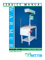
1
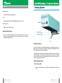
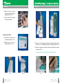
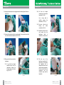
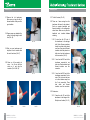
W A R M E R
V 3.10 - 318
ISO 13485 : 2003
Important information
This manual will help you perform preventive maintenance on your MTTS Warmer
device.
Preventive maintenance should be performed every 6 months and all the information
required is enclosed in this manual. Your Warmer came with a tool box which contains
all the tools and spare parts for the first session of preventive maintenance.
For all further maintenance you will have to order spare parts from MTTS.
The tool box includes:
Heater element holder
Transformer
Light bulb
Switch for halogen light
Halogen light connector and wires
Thermal wire insulation
If you have any technical problems please call the MTTS hotline at:
Tel: + 84 43 766 6521
Fax: + 84 43 766 3844
Email: [email protected]
Contact person: Mr. Trần Sỹ Huấn
WARMER 3.10 - 3.18 VER1.1
2
General technical information
Table of contents
Warmer model: 3.10 - 3.18
Important information2
Warranty: 1 year
General technical information3
Expected service life: 5 years
Table of contents 4
Operating conditions: the warmer has been tested to function properly in 23-30 C. If
possible, use the warmer in environments within this temperature range.
o
Storage conditions: Keep the unit covered with a cloth or plastic cover to prevent it getting dusty or dirty. Store in a dry environment.
Class I Medical Electrical Equipment. Warning: to avoid the risk of electric shock, the
warmer must only be connected to a supply mains with protective earth.
Not classified against ingress of liquids.
Assembly5
Introduction9
Warmer System10
Control Unit11
Heating System14
50-60 Hz
Temperature Sensor32
180-240V
300W (@180V) – 550W (@240V)
Folding Table and Bed33
Warning: Do not modify this equipment without authorization of the manufacturer.
Troubleshooting34
Warning: dispose of equipment properly at end of equipment service life.
Warmer Test Report35
2
3
WARMER 3.10 - 3.18 VER1.1
3
WARMER 3.10 - 3.18 VER1.1
4
Assembly
Step 1:
Take the cardboard box apart using
a sharp knife or scissors. (Pic.1).
Assembly
Insert the enclosed pieces of black
plastic to ensure a tight fit. (Pic. 5).
Take the Warmer out of the box.
(Pic.2).
Pic. 1
Step 3:
Insert the overhead stand into the
bed at the available hole. (Pic.3).
Step 2:
Pic. 2
The 2 holes on the stand and 2
holes on the bed should align. Use
one hand to hold the stand and the
other hand to insert the screw. (Pic. 4).
Pic. 5
Step 4:
Assemble the heating system onto
the stand. (Pic. 7, 8).
Pic. 7
Pic. 3
5
WARMER 3.10 - 3.18 VER1.1
Tighten the screws with a spanner.
Make sure washers are used.
(Pic. 6).
Pic. 6
Pic. 8
Pic. 4
WARMER 3.10 - 3.18 VER1.1
6
Assembly
Assembly
Ensure the holes of the frame align
with the holes of the heating
system. (Pic. 9).
Pic. 9
Screw 4 screws into the heating
system by hand. (Pic. 10).
This photo shows the 4 screws
temporarily holding the heating
system in place. (Pic. 11).
Pic. 11
7
WARMER 3.10 - 3.18 VER1.1
Step 5:
Connect electric wires
This photo shows the lead from the
control unit. (Pic. 13).
Connect the lead from the control
unit to the heating system. Twist
the connector clockwise to tighten
it into place. (Pic.14).
Pic. 10
Pic.13
Using a spanner, tighten all 4
screws. (Pic. 12).
Pic. 12
Connect the power cable to the
control unit. (Pic. 15).
Pic. 15
Pic. 14
Plug the sensor into the front panel.
(Pic. 16).
Pic. 16
WARMER 3.10 - 3.18 VER1.1
8
Introduction
The MTTS WARMER is designed to keep infants warm in first aid emergencies or
medical environments that require an appropriate temperature. It monitors the
body temperature of the patient and adjusts the heat according to a desired set
temperature.
Before beginning any technical tasks, DO NOT FORGET to engage the brake on
the wheels in order to prevent the Warmer from moving. Turn OFF the Warmer and
unplug it from 220V.
Warmer System
The MTTS Warmer system is composed of:
1
Heating System
2
Control Unit
1. Heating System
Sensor
3
4
Folding Table and Bed
2. Control Unit
3. Sensor
4. Folding Table
and Bed
Pic. 17
9
WARMER 3.10 - 3.18 VER1.1
WARMER 3.10 - 3.18 VER1.1
10
Control Unit
Control Unit
Sensor Temperature Dial
Alarm Speaker
Alarm Visual Indicator
Alarm Mute Switch
This dial sets the desired temperature of the baby/warmer mattress. The possible temperature range is 32 – 38oC in 0.1oC increments. It is set by the user. Turning the dial clockwise increases the temperature setting and counterclockwise dcreas-
es the temperature setting.
Alarm Speaker
Set Temperature Display
Set Temperature Knob
Sensor Temperature
Display
Heater Power Display
When an alarm condition exists, the speaker will sound. An alarm condition will
occur when the temperature of the sensor is higher than the set temperature, or if
the sensor cannot make an accurate temperature reading.
Horizontal LED display
Sensor Connector
On/Off Switch
Pic. 18
OPERATING PRINCIPLE:
The control unit is used to control all the functions of the Warmer. It also provides
the user with visual displays describing Warmer operating conditions.
This displays the temperature recorded by the skin sensor (the baby’s skin tepera-
ture). The sensor has an accuracy of +/- 0.3oC and a range of 19.5-45.8oC.
Horizontal LCD display
The top line displays the set temperature dialed by the user (32-38oC) and any relevant messages or warnings. The bottom line displays the APGAR clock after the initial warm-up period.
APGAR button
Front of control unit
On/Off Switch
Sensor connector
Site where the skin temperature sensor is plugged in. Use only MTTS temperature sensors.
Turns the power on/off for the whole warmer
Alarm system:
-
-
11
Alarm ‘speaker’: sounds when there is an alarm condition.
Alarm button: light flashes when an alarm condition exists. Pressing this button turns the alarm speaker/audible alarm off for 9 minutes.
WARMER 3.10 - 3.18 VER1.1
Pressing this button starts the APGAR timer. Alarm indicates after 1 min, 5 min, 10 min, 20 min and 30 min.
Back of control unit
220V power inlet
Connect grounded power cord from grounded wall outlet to socket.
WARMER 3.10 - 3.18 VER1.1
12
Control Unit
Heating System
Diagnostic buttons
Used by MTTS staff during maintenance.
Fuses
Replaceable safety fuses (5A/250V AC@50A slow blow 5 x 20 mm).
220V heater outlet
Light Switch
Supplies power to heater element.
PREVENTIVE MAINTENANCE:
There is no preventive maintenance required for the Control Unit. However, it
should be inspected every 6 months by a hospital technician and any failures
immediately reported to MTTS.
Heater element
Halogen Bulb
Pic. 19
OPERATING PRINCIPLE:
This part of the warmer houses the heater element and a halogen light source. The
heater element can provide up to 500W and is regulated by the temperature sensor.
The heating system is insulated with fibreglass.
A halogen lamp on the warmer provides light for health workers to treat, check and
care for the patient. Turn it off after use to conserve the life of the lamp. The halogen
lamp is not a light to be used for the treatment of jaundice. A switch on the end of the
unit turns the halogen light on and off.
PREVENTIVE MAINTENANCE:
1. Replace Halogen Bulb
1.1.Ensure the entire Warmer is turned off by turning the switch off on the Control
Unit.
13
WARMER 3.10 - 3.18 VER1.1
WARMER 3.10 - 3.18 VER1.1
14
Heating System
Heating System
1.2.Wait for the bulb to cool down.
Grasp the halogen bulb using your
fingertips and pull. (Pic. 20).
1.3.Insert a new bulb. The polarity of
the bulb is not important.
Pic. 20
2. Replace Element Holder
2.1. Remove the 4 screws at the end
of the Heating System. (Pic. 21).
Pic. 24
Pic. 25
2.3. Remove all of the fibreglass insulation within the Heating System. Ensure
gloves are worn as the fibreglass particles are highly irritating. (Pic.24, 25).
2.2.
Remove the top cover of the
Heating System. (Pic. 22, 23).
2.4. Use pliers or a spanner to remove the nuts on the outer threads. Also remove
the washers. (Pic.26).
Pic. 21
Note the order that the nuts and washers are on the thread. (Pic.27).
Nut
Nut
Washer
Lug
Washer
Nut
Nut
Pic. 22
15
WARMER 3.10 - 3.18 VER1.1
Pic. 23
Pic.26
Pic. 27
WARMER 3.10 - 3.18 VER1.1
16
Heating System
Heating System
Pic. 28
2.5.Remove the nuts on the central
thread. Note that you may need to
hold the inner nut still as shown
in pic 28.
Also remove the washers and the
wire lug.
Pic. 30
2.8.
Replace
all
of
the
nuts,
washers and wire lugs in the
correct order as shown in Pic. 30.
2.10.Replace the top cover at the
heating system.
17
Pic. 29
2.6.
Remove the damaged
element holder. (Pic. 29).
Pic. 32
heater
2.7.
Replace the broken heater
element holder with a new one.
3. Replace Transformer
3.1.Remove the 4 screws at the end
of the Heating System. (Pic. 32).
3.2.
Remove the top cover of the
Heating System. (Pic. 33, 34).
3.3.Remove all of the fibreglass
insulation within the Heating
System. Ensure gloves are worn
as the fibreglass particles are
highly irritating. (Pic. 35, 36).
Pic. 34
Pic. 31
2.9. Replace the insulation. Ensure
that the insulation does not
touch the halogen bulb, and that
there is at least 5cm of space
around the bulb. (Pic. 31)
2.11.Replace the front plate and 4
screws.
Pic. 35
WARMER 3.10 - 3.18 VER1.1
Pic.33
Pic. 36
WARMER 3.10 - 3.18 VER1.1
18
Heating System
Heating System
3.4.Unscrew the transformer’s mounting plate from the Heating System Enclosure .
(Pic.37, 38).
3.6.2.
Pull back the thermal
insulation so you can see the
heatshrink. (Pic. 42).
Use a sharp knife to
carefully
remove
the
heatshrink. (Pic. 43, 44).
3.6.3.Use wire - cutters to cut
through
the
solder
connections. (Pic. 45).
Pic. 37
Pic. 38
3.5.Unscrew the transformer from its mounting plate. You may need to secure the
nut on the other side as shown here. (Pic. 39, 40).
Pic. 39
Pic. 40
3.6.1.If you follow the thermal
insulation away from the
transformer towards the
halogen light you will notice
a gap. (Pic. 41).
Pic. 41
WARMER 3.10 - 3.18 VER1.1
Pic. 43
Pic. 42
Pic. 44
3.6.5.
The last wire of the
transformer is soldered to 2
other wires. Do not remove
the heatshrink that is
already there and do not cut
into the existing connection.
For this wire cut it off a few
centimetres
from
the
connection away from the
heatshrink.
3.6. Disconnect all of the wires from the
transformer.
19
3.6.4.Repeat this process for the
wire coming from the
transformer
which
is
soldered to one other wire.
Pic. 45
WARMER 3.10 - 3.18 VER1.1
20
Heating System
Heating System
3.7.
Remove the old transformer.
Make sure you keep the bits of
thermal insulation if they are still in
good condition.
3.8.Prepare some new heatshrink by
cutting it to the right length - about
2cm. (Pic. 46).
3.11. Tin all of the wires. (Pic. 51).
3.12.There are 4 wires coming from the
transformer that need to be soldered.
Each one requires heatshrink and
thermal insulation in the configuration
shown below. Make sure to place the
heatshrink and insulation before
soldering.
3.12.1. 2 wires from the 12V end of
the transformer to the halogen
bulb. Each of these connections
should have heat shrink placed
over them. One piece of thermal
insulation should be placed over
both wires from the transformer
to this connection. (Pic. 52).
3.12.2. 1 wire from the 220V end of the
transformer connected to one
other wire. Place heat shrink and
thermal insulation over this
connection.
3.12.3. 1 wire from the 220V end of the
transformer connected to 2 other
wires. (This is the wire that was
cut a short distance away from
the 3 wire connection). Place
heat
shrink
and
thermal
insulation over this connection.
Pic. 46
3.9.Take your new transformer and
strip about 1cm of insulation from
the end of each wire. (Pic. 47).
3.10.Clean up all the recently cut
wires - cut off wire that has
solder on it and strip the
insulation. (Pic. 48, 49, 50).
Pic. 47
21
WARMER 3.10 - 3.18 VER1.1
Pic. 49
Pic. 50
Pic. 52
3.13. Solder wires:
Pic. 48
Pic. 51
3.13.1.2 wires from the 12V end of the
transformer to the halogen bulb.
Polarity doesn’t matter. (Pic. 53).
Pic. 53
WARMER 3.10 - 3.18 VER1.1
22
Heating System
Heating System
4. Replace Light Switch
3.13.2. 1 wire from the 220V end of
the transformer connected
to the single wire.
4.1.Remove the 4 screws at the end
of the Heating System. (Pic. 57).
3.13.3. 1 wire from the 220V end of
the transformer connected
to 2 other wires.
3.14.Slide the heatshrink into the
correct position and use a heat
gun or a lighter to shrink the
heatshrink around the bare
metal. (Pic. 54, 55).
3.15.Screw the transformer into its
mounting plate.
Replace the fibreglass insulation.
Ensure gloves are worn as the
fibreglass particles are highly
irritating.
Ensure
that
the
insulation does not touch the
halogen bulb, and that there is at
least 5cm of space around the
bulb. (Pic. 56).
4.2.Use a sharp knife to remove the
heatshrink from the old switch.
(Pic. 58).
Pic. 54
3.16.
Screw
the
transformer’s
mounting plate into the Heating
System Enclosure.
3.17.
Pic. 57
4.3.Desolder the wires going to the
old switch. (Pic. 59).
Pic. 58
4.4. Remove old switch. (Pic. 60).
Pic. 55
3.18.Replace the top cover of the
Heating System.
3.19. Replace the cover plate using 4
screws.
Pic. 56
23
WARMER 3.10 - 3.18 VER1.1
Pic. 59
4.5.Clean up the recently cut wires cut off wire that has solder on
it and strip the insulation. Tin all of
the wires.
Pic. 60
4.6.Insert a new switch. Make sure
the ‘1’ symbol is at the top.
WARMER 3.10 - 3.18 VER1.1
24
Heating System
Heating System
4.7.Slide heatshrink onto all wires
about to be soldered.
4.8.Solder wires to the switch. Make
sure you solder to a vertical pair of
pins on the switch - the polarity
doesn’t matter.
4.9.
Slide the heatshrink into the
correct position and use a heat
gun to shrink the heatshrink
around the connection. (Pic. 61).
Pic. 61
4.10.Replace the cover plate using
4 screws.
5. Replace burnt wire.
Pic. 64
The most common wires that require
changing are those that go from the
transformer to the light bulb.
5.1.Remove the 4 screws at the
of the Heating System. (Pic.
5.2.
Remove the top cover of
Heating
System.
(Pic.
end
62).
Pic. 62
the
63).
Pic. 65
5.3.Remove
enough
fibreglass
insulation within the Heating
System to give you room to work.
Ensure gloves are worn as the
fibreglass particles are highly
irritating. (Pic. 64, 65).
5.4.Remove the Halogen light bulb.
Make sure the bulb doesn’t fall
onto a hard surface and break
(Pic. 66).
5.5.Use your fingers and a knife to
remove the silicon attaching the
wires to the mounting bracket.
Pic. 66
Screwdriver holding the
screw still from the other side
5.6.Remove the screw and nut from
the bulb mounting plate by using a
screwdriver and something to hold
the nut still. (Pic. 67).
Pic. 63
25
WARMER 3.10 - 3.18 VER1.1
Pic. 67
WARMER 3.10 - 3.18 VER1.1
26
Heating System
Heating System
5.7. Remove the bulb-holder from
the mounting plate and cut the
wires. (Pic. 68, 69).
5.8.
Take a replacement set of wires
with bulb-holder (in this case
you should have some in your
toolbox) and prepare the ends of
all wires by stripping the
insulation and tinning them.
5.9.Slide thermal insulation
heatshrink onto the wires.
5.14.Replace the fibreglass insulation.
Ensure gloves are worn as the
fibreglass particles are highly
irritating.
Ensure
that
the
insulation does not touch the
halogen bulb. and that there is at
least 5cm of space around the
bulb. (Pic 71).
Pic. 68
6. Replace Heater Element.
6.1. Remove the 4 screws at the end
of the Heating System. (Pic. 72).
6.2.Remove the top cover of the
Heating System. (Pic. 73, 74).
Pic. 69
Pic. 70
27
WARMER 3.10 - 3.18 VER1.1
Pic. 71
5.16.Replace the cover plate using
4 screws.
and
5.10.Solder the wires together. Note
that polarity isn’t important.
(Pic. 70).
5.11.Use a heat gun or lighter to melt
the heatshrink around the wires.
5.12.Screw the new bulb-holder back
into the mounting plate.
5.13.Place silicon around the back
of the bulb holder to stop the
wires from moving and to keep
the thermal insulation in place.
5.15.Replace the top cover of the
Heating System.
Pic. 72
Pic. 73
Pic. 74
WARMER 3.10 - 3.18 VER1.1
28
Heating System
Heating System
Pic. 79
Pic. 75
6.3.Remove all of the fibreglass
insulation within the Heating
System. Ensure gloves are worn
as the fibreglass particles are
highly irritating. (Pic. 75, 76).
6.5.Remove the nuts on the central thread. Note that you may need to hold the
inner nut still, as shown here. Also remove the washers and the wire lug. (Pic. 79).
6.6.Remove the heater element holder. (Pic. 80).
6.7.Remove the nuts and washers on the other end of the central thread of the
heater element.
6.8.Slide out the heater element. (Pic. 81, 82).
Pic. 76
6.4.Use pliers or a spanner to remove
the nuts on the outer threads. Also
remove the washers. (Pic. 77).
Note the order that the nuts and
washers are on the thread.
(Pic. 78).
Nut
Nut
Washer
Lug
Washer
Nut
Nut
Pic. 77
Pic. 80
Slide the heater element out in this direction
Pic. 81
Pic. 78
Pic. 82
29
WARMER 3.10 - 3.18 VER1.1
WARMER 3.10 - 3.18 VER1.1
30
Temperature Sensor
Heating System
6.9. To test the heater element, use a multimeter to ensure the resistance from one
end to the other is between 95 and 100 ohm. (Pic. 83).
Operating Principle:
The temperature sensor measures the temperature of whatever it is attached to.
Preventive Maintenance:
There is no preventive maintenance required for the Temperature Sensor. However,
it should be inspected every 6 months by a hospital technician and any failures
immediately reported to MTTS.
Pic. 83
6.10.Slide a new heater element into the warmer system all the way, then bring it
back 5mm so it has room to expand when hot. Also make sure that the heater
element is 20mm from the top of the reflector.
6.11.Replace all of the nuts, washers and wire lugs in the correct order as shown
here. (Pic. 84).
6.12.Replace the insulation. Ensure that the insulation does not touch the halogen
bulb, and that there is at least 5cm of space around the bulb. (Pic.85).
6.13.Replace the front and top plate.
Nut
Nut
Nut
Nut
Washer
Washer
Lug
Lug
Washer
Washer
Nut
Nut
Nut
Nut
Pic. 84
31
WARMER 3.10 - 3.18 VER1.1
Pic. 85
WARMER 3.10 - 3.18 VER1.1
32
Folding Table and Bed
Troubleshooting
Operating Principle:
The heater element never seems to warm up
The Bed is used to provide a location for the baby to receive treatment by the Warmer.
The folding bed is used as a convenient location to put equipment or miscellaneous items.
•
•
Preventive Maintenance:
There is no preventive maintenance required for the folding table and bed. However,
every 6 months the folding table should be inspected by raising and lowering the
fonding bed to ensure it moves easily and locks into the upright position securely.
Check that the side panels of the bed can be moved up and down easily. Any failures
should be immediately reported to MTTS.
If the set temperature is below the ambient temperature the heater element will
not turn on. The warmer is working properly.
Ensure the cable from the control unit to the heating system is not damaged and
is connected properly. If the problem persists, please call MTTS for service.
The displays on the control unit do not illuminate
• Ensure the power cable to the control unit is not damaged and is connected
properly.
The display is showing garbage information
• Try resetting the machine by turning the power off and back on again. If the
problem persists, please call MTTS for service.
The alarms do not stop
33
WARMER 3.10 - 3.18 VER1.1
•
If the “Temp too low !” or “Temp too high !” alarms is on, it means that the sensor
temperature is out of range from the set temperature. To test this, move the sensor
closer/farther from the heater so that it can become with +/- 1o of the set point. If the
alarm stops, then the warmer is working properly. If the alarm continues, call MTTS
for service.
•
If the “Sensor failure !” alarm is on, this means that the skinsensor is unplugged or it
is broken. Plug the sensor back in if it is unplugged. If the sensor is plugged in and the
screen still reads “Sensor failure !”, this means the sensor is broken. Replace the sensor.
•
If the “Sensor off baby!” alarm is on, this means that the baby sensor is suspected to not
be on the baby. Place the sensor on the baby and wait 5 minutes. If the alarm does not
turn off automatically, restart the warmer. If problem persists, call MTTS for assistance.
•
If the “Amb.Sensor fail!” alarm is on, this means that the ambient temperature sensors are not functioning properly. Call MTTS for assistance.
WARMER 3.10 - 3.18 VER1.1
34
WARMER MTW 0603/4 VER1.1
Troubleshooting
The warmer system is hot to touch
• The warmer system is usually warm to touch, however, if it becomes too hot,
open the warmer system and check a) that there is enough insulation and b) that
it has been placed correctly.
• If the problem persists, discontinue use and call MTTS for service.
There is smoke or a burning smell coming from the warmer
• Immediately turn off the warmer.
• Open the warmer system and check to see if any wires look burnt. If so, replace
them. Make sure that the insulation is inserted correctly (see instructions).
• If the problem persists, discontinue use and call MTTS for service.
When any metal on the warmer is touched, one can feel a tingling sensation
• This can be caused by inadequate earthing of the warmer. Make sure that the
power cable from the wall to the control unit has an earth pin (there should be 3
pins). Try a different 3-pin cable to test if it is damaged.
• Ensure the power cable is connected securely.
• Some hospitals do not have an adequate earth connection. If you continue to
notice a tingling sensation, switch off the warmer immediately, discontinue use,
and call MTTS for service.
The warmer is uneven on the ground.
• There is a hexagonal nut just above each wheel - turn one of these nuts to
change the height of the leg.
The warmer seems too hot/cold.
It is very difficult to determine if the warmer is at the right temperature using your
senses. Your perception of temperature can change depending on your health, your
mood, ambient environmental conditions, amongst many other things. If you suspect
the warmer is not at the right temperature, place a thermometer in the centre of the
bed and set the warmer temperature to be 4 degrees above the ambient temperature.
If, after 10 minutes, the thermometer is not within 2 degrees of the set temperature
then the warmer must be recalibrated. Please call MTTS for this to occur. Note that
the warmer can only raise the temperature. If the set temperature is below the
ambient temperature, the heating system will not operate.
35
WARMER 3.10 - 3.18 VER1.1
WARMER TEST REPORT
HOSPITAL NAME:S/N:
DATE:
TESTED BY:
APPROVED BY:
#
1
2
3
TEST:
TURN ON THE WARMER
LCD display
Red 7segment display
Alarm test
EXPECTED RESULT:
Visible blue backlight and clear text
7segment display is clear and correct
Short beep during startup; alarm light
is on during beep
Clear and correct
4 Heater bargraph display
LCD display shows correct nr. Hours
5 Press button 1
and clock
LCD display shows 4 correct
6 Press button 2
temperatures
1 = babysensor temp; 2,3 = ambient
temp; 4 = OFF
7 Turn up/down settemp knob Temperature in 7segment display
should go up/down. (Min = 32oC
Max = 38.9oC)
Bargraph display also changes
up/down
Halogen light working correct
8 Turn ON/OFF the
Halogen light on the top
Bed should warm up and LCD display
9 After a few minutes
shows correct babysensor temp.
Alarm should raise when
10 Alarm test: heat up
o
babysensor >39oC
babysensor to 40 C
Turn off warmer for 10m and wait
Turn on again
Heaterpower =100% (warming up),
11 Look at heaterpower
after few minutes heaterpower should
decrease
Tests 1-11 are OK
12 Settemp = 38oC
and temperature of bed
Warmer ON at least
(babysensor) is close to 38oC
2 hours
After 2h repeat tests 1-11
TURN OFF THE WARMER
DATE:
TESTED:
APPROVED:
OK FAIL
??
WARMER MTW 0603/4 VER1.1
WARMER TEST REPORT
HOSPITAL NAME:S/N:
DATE:
TESTED BY:
APPROVED BY:
#
1
2
3
TEST:
TURN ON THE WARMER
LCD display
Red 7segment display
Alarm test
EXPECTED RESULT:
Visible blue backlight and clear text
7segment display is clear and correct
Short beep during startup; alarm light
is on during beep
Clear and correct
4 Heater bargraph display
LCD display shows correct nr. Hours
5 Press button 1
and clock
LCD display shows 4 correct
6 Press button 2
temperatures
1 = babysensor temp; 2,3 = ambient
temp; 4 = OFF
7 Turn up/down settemp knob Temperature in 7segment display
should go up/down. (Min = 32oC
Max = 38.9oC)
Bargraph display also changes
up/down
Halogen light working correct
8 Turn ON/OFF the
Halogen light on the top
Bed should warm up and LCD display
9 After a few minutes
shows correct babysensor temp.
Alarm should raise when
10 Alarm test: heat up
o
babysensor >39oC
babysensor to 40 C
Turn off warmer for 10m and wait
Turn on again
Heaterpower =100% (warming up),
11 Look at heaterpower
after few minutes heaterpower should
decrease
Tests 1-11 are OK
12 Settemp = 38oC
and temperature of bed
Warmer ON at least
(babysensor) is close to 38oC
2 hours
After 2h repeat tests 1-11
TURN OFF THE WARMER
DATE:
TESTED:
APPROVED:
OK FAIL
??
MEDICAL TECHNOLOGY TRANSFER AND SERVICES
No 2 - Lane 70 - Linh Lang, Ba Dinh, Hanoi, Vietnam
Tel: + 84 43 766 6521
Fax: + 84 43 766 3844
Email: [email protected]
www.mtts-asia.com
WARMER 3.10 - 3.18 VER 1.1