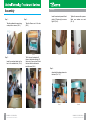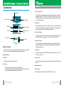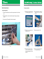
1
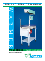
USER AND SERVICE MANUAL
W A R M E R
V1-V3 SERIES
EN ISO 13485 : 2012
WARMER V1 - V3 SERIES REV2.01
Important information
This manual will help you install and perform preventive maintenance on your MTTS
Warmer device.
Refer to MTTS Youtube channel for more instructions:
https://www.youtube.com/user/MTTSasia
Note that preventive maintenance should be performed every 6 months and all the
information required is enclosed in this manual.
If you have any technical problems please contact nearest MTTS distributor. List of
distributors can be found at:
www.mtts-asia.com/contact
WARMER V1 - V3 SERIES REV2.01
REV2.00
2
General technical information
Table of contents
Warmer model: V1-V3 Series
Important information2
Warranty: 1 year
General technical information3
Expected service life: 5 years
Table of contents 4
Operating conditions: the warmer has been tested to function properly in 19-40 C. If
possible, use the warmer in environments within this temperature range.
o
Storage conditions: Keep the unit covered with a cloth or plastic cover to prevent it getting dusty or dirty. Store in a dry environment.
Class I Medical Electrical Equipment. Warning: to avoid the risk of electric shock, the
warmer must only be connected to a supply mains with protective earth.
Not classified against ingress of liquids.
Assembly5
Introduction9
Warmer System10
Control Unit11
Heating System14
50-60 Hz
Temperature Sensor18
180-240V
300W (@180V) – 550W (@240V)
Folding Table and Bed19
Warning: Do not modify this equipment without authorization of the manufacturer.
Troubleshooting20
Warning: dispose of equipment properly at end of equipment service life.
2
3
WARMER
WARMER V1-V3
V1 - V3SERIES
SERIESREV2.01
REV2.01
3
WARMER V1 - V3 SERIES REV2.01
4
Assembly
Step 1:
Take the cardboard box apart using
a sharp knife or scissors. (Pic.1).
Assembly
Pic. 1
Step 3:
Insert the overhead stand into the
bed at the available hole. (Pic.3).
Step 2:
Take the Warmer out of the box.
(Pic.2).
Pic. 2
The 2 holes on the stand and 2
holes on the bed should align (V1 Series only). Use one hand to hold the stand and the other hand to insert the screw. (Pic. 4).
Insert the enclosed pieces of black plastic (V1 Series only) to ensure a tight fit. (Pic. 5).
Pic. 5
Step 4:
Assemble the heating system onto
the stand. (Pic. 7, 8).
Pic. 7
Pic. 3
5
WARMER V1 - V3 SERIES REV2.01
Tighten the screws with a spanner.
Make sure washers are used.
(Pic. 6).
Pic. 6
Pic. 8
Pic. 4
WARMER V1 - V3 SERIES REV2.01
6
Assembly
Assembly
Ensure the holes of the frame align
with the holes of the heating
system. (Pic. 9).
Pic. 9
Screw 4 screws into the heating
system by hand. (Pic. 10).
This photo shows the 4 screws
temporarily holding the heating
system in place. (Pic. 11).
Pic. 11
7
WARMER V1 - V3 SERIES REV2.01
Step 5:
Connect electric wires
This photo shows the lead from the
control unit. (Pic. 13).
Connect the lead from the control
unit to the heating system. Twist
the connector clockwise to tighten
it into place. (Pic.14).
Pic. 10
Pic.13
Using a spanner, tighten all 4
screws. (Pic. 12).
Pic. 12
Connect the power cable to the
control unit. (Pic. 15).
Pic. 15
Pic. 14
Plug the sensor into the front panel.
(Pic. 16).
Pic. 16
WARMER V1 - V3 SERIES REV2.01
8
Introduction
The MTTS WARMER is designed to keep infants warm in first aid emergencies or
medical environments that require an appropriate temperature. It monitors the
body temperature of the patient and adjusts the heat according to a desired set
temperature.
Before beginning any technical tasks, DO NOT FORGET to engage the brake on
the wheels in order to prevent the Warmer from moving. Turn OFF the Warmer and
unplug it from 220V.
Warmer System
The MTTS Warmer system is composed of:
1
Heating System
2
Control Unit
1. Heating System
Sensor
3
4
Folding Table and Bed
2. Control Unit
3. Sensor
4. Folding Table
and Bed
Pic. 17
9
WARMER V1 - V3 SERIES REV2.01
WARMER V1 - V3 SERIES REV2.01
10
Control Unit
Control Unit
Sensor Temperature Dial
Alarm Speaker
Alarm Visual Indicator
Alarm Mute Switch
This dial sets the desired temperature of the baby/warmer mattress. The possible temperature range is 32 – 38oC in 0.1oC increments. It is set by the user. Turning the dial clockwise increases the temperature setting and counterclockwise dcreas-
es the temperature setting.
Alarm Speaker
LED Display
Set Temperature Knob
LCD Display
APGAR Timer Start
Button
When an alarm condition exists, the speaker will sound. An alarm condition will
occur when the temperature of the sensor is higher than the set temperature, or if
the sensor cannot make an accurate temperature reading.
Horizontal LED display
Sensor Connector
On/Off Switch
Pic. 18
OPERATING PRINCIPLE:
The control unit is used to control all the functions of the Warmer. It also provides
the user with visual displays describing Warmer operating conditions.
This displays the temperature recorded by the skin sensor (the baby’s skin tepera-
ture). The sensor has an accuracy of +/- 0.3oC and a range of 19.5-45.8oC.
Horizontal LCD display
The top line displays the set temperature dialed by the user (32-38oC) and any relevant messages or warnings. The bottom line displays the APGAR clock after the initial warm-up period.
APGAR button
Front of control unit
On/Off Switch
Sensor connector
Site where the skin temperature sensor is plugged in. Use only MTTS temperature sensors.
Turns the power on/off for the whole warmer.
Alarm system:
-
-
11
Alarm ‘speaker’: sounds when there is an alarm condition.
Alarm button: light flashes when an alarm condition exists. Pressing this button turns the alarm speaker/audible alarm off for 9 minutes.
WARMER V1 - V3 SERIES REV2.01
Pressing this button starts the APGAR timer. Alarm indicates after 1 min, 5 min, 10 min, 20 min and 30 min.
Back of control unit
220V power inlet
Connect grounded power cord from grounded wall outlet to socket.
WARMER V1 - V3 SERIES REV2.01
12
Heating System
Control Unit
Diagnostic buttons
Used by MTTS staff during maintenance.
Fuses
Replaceable safety fuses (5A/250V AC@50A slow blow 5 x 20 mm).
Light Switch
220V heater outlet
Supplies power to heater element.
PREVENTIVE MAINTENANCE:
Heater element
There is no preventive maintenance required for the Control Unit. However, it
should be inspected every 6 months by a hospital technician and any failures
immediately reported to MTTS.
Halogen Bulb
Pic. 20
OPERATING PRINCIPLE:
This part of the warmer houses the heater element and a halogen light source. The
heater element can provide up to 500W and is regulated by the temperature sensor.
The heating system is insulated with fibreglass.
A halogen lamp on the warmer provides light for health workers to treat, check and
care for the patient. Turn it off after use to conserve the life of the lamp. The halogen
lamp is not a light to be used for the treatment of jaundice. A switch on the end of the
unit turns the halogen light on and off.
Pic. 19
13
WARMER V1 - V3 SERIES REV2.01
WARMER V1 - V3 SERIES REV2.01
14
Heating System
Heating System
PREVENTIVE MAINTENANCE:
2. Replace Light Switch
1. Replace Halogen Bulb
2.1.Remove the 4 screws at the end
of the Heating System. (Pic. 22).
1.1.Ensure the entire Warmer is turned off by turning the switch off on the Control
Unit.
1.2.Wait for the bulb to cool down. Grasp the halogen bulb using your fingertips and pull.
2.2.Use a sharp knife to remove the
heatshrink from the old switch.
(Pic. 23).
1.3.Insert a new bulb. The polarity of the bulb is not important.
Pic. 22
2.3.Desolder the wires going to the
old switch. (Pic. 24).
Pic. 21
Pic. 24
2.5.Clean up the recently cut wires cut off wire that has solder on
it and strip the insulation. Tin all of
the wires.
15
WARMER V1 - V3 SERIES REV2.01
Pic. 23
2.4. Remove old switch. (Pic. 25).
Pic. 25
2.6.Insert a new switch. Make sure
the ‘1’ symbol is at the top.
WARMER V1 - V3 SERIES REV2.01
16
Temperature Sensor
Heating System
2.7.Slide heatshrink onto all wires
about to be soldered.
Operating Principle:
2.8.Solder wires to the switch. Make
sure you solder to a vertical pair of
pins on the switch - the polarity
doesn’t matter.
2.9.
Slide the heatshrink into the
correct position and use a heat
gun to shrink the heatshrink
around the connection. (Pic. 26).
The temperature sensor measures the temperature of whatever it is attached to.
Preventive Maintenance:
There is no preventive maintenance required for the Temperature Sensor. However,
it should be inspected every 6 months by a hospital technician and any failures
immediately reported to MTTS.
Pic. 26
2.10.Replace the cover plate using
4 screws.
17
17
WARMER V1 - V3 SERIES REV2.01
WARMER V1 - V3 SERIES REV2.01
18
Folding Table and Bed
Troubleshooting
Operating Principle:
The heater element never seems to warm up
The Bed is used to provide a location for the baby to receive treatment by the Warmer.
The folding bed is used as a convenient location to put equipment or miscellaneous items.
•
•
Preventive Maintenance:
There is no preventive maintenance required for the folding table and bed. However,
every 6 months the folding table should be inspected by raising and lowering the
fonding bed to ensure it moves easily and locks into the upright position securely.
Check that the side panels of the bed can be moved up and down easily. Any failures
should be immediately reported to MTTS.
If the set temperature is below the ambient temperature the heater element will
not turn on. The warmer is working properly.
Ensure the cable from the control unit to the heating system is not damaged and
is connected properly. If the problem persists, please call MTTS for service.
The displays on the control unit do not illuminate
• Ensure the power cable to the control unit is not damaged and is connected
properly.
The display is showing garbage information
• Try resetting the machine by turning the power off and back on again. If the
problem persists, please call MTTS for service.
The alarms do not stop
19
WARMER V1 - V3 SERIES REV2.01
•
If the “Temp too low !” or “Temp too high !” alarms is on, it means that the sensor
temperature is out of range from the set temperature. To test this, move the sensor
closer/farther from the heater so that it can become with +/- 1o of the set point. If the
alarm stops, then the warmer is working properly. If the alarm continues, call MTTS
for service.
•
If the “Sensor failure !” alarm is on, this means that the skinsensor is unplugged or it
is broken. Plug the sensor back in if it is unplugged. If the sensor is plugged in and the
screen still reads “Sensor failure !”, this means the sensor is broken. Replace the sensor.
•
If the “Sensor off baby!” alarm is on, this means that the baby sensor is suspected to not
be on the baby. Place the sensor on the baby and wait 5 minutes. If the alarm does not
turn off automatically, restart the warmer. If problem persists, call MTTS for assistance.
•
If the “Amb.Sensor fail!” alarm is on, this means that the ambient temperature sensors are not functioning properly. Call MTTS for assistance.
WARMER V1 - V3 SERIES REV2.01
20
Troubleshooting
The warmer system is hot to touch
• The warmer system is usually warm to touch, however, if it becomes too hot,
open the warmer system and check a) that there is enough insulation and b) that
it has been placed correctly.
• If the problem persists, discontinue use and call MTTS for service.
There is smoke or a burning smell coming from the warmer
• Immediately turn off the warmer.
• Open the warmer system and check to see if any wires look burnt. If so, replace
them. Make sure that the insulation is inserted correctly (see instructions).
• If the problem persists, discontinue use and call MTTS for service.
When any metal on the warmer is touched, one can feel a tingling sensation
• This can be caused by inadequate earthing of the warmer. Make sure that the
power cable from the wall to the control unit has an earth pin (there should be 3
pins). Try a different 3-pin cable to test if it is damaged.
• Ensure the power cable is connected securely.
• Some hospitals do not have an adequate earth connection. If you continue to
notice a tingling sensation, switch off the warmer immediately, discontinue use,
and call MTTS for service.
The warmer is uneven on the ground.
• There is a hexagonal nut just above each wheel - turn one of these nuts to
change the height of the leg.
The warmer seems too hot/cold.
It is very difficult to determine if the warmer is at the right temperature using your
senses. Your perception of temperature can change depending on your health, your
mood, ambient environmental conditions, amongst many other things. If you suspect
the warmer is not at the right temperature, place a thermometer in the centre of the
bed and set the warmer temperature to be 4 degrees above the ambient temperature.
If, after 10 minutes, the thermometer is not within 2 degrees of the set temperature
then the warmer must be recalibrated. Please call MTTS for this to occur. Note that
the warmer can only raise the temperature. If the set temperature is below the
ambient temperature, the heating system will not operate.
21
WARMER V1 - V3 SERIES REV2.01
MEDICAL TECHNOLOGY TRANSFER AND SERVICES
No 26 - Lane 41 - An Duong Vuong, Ho Tay, Hanoi, Vietnam
Tel: + 84 24 3766 6521
Fax: + 84 24 3718 8050
Email: [email protected]
www.mtts-asia.com
WARMER V1-V3 SERIES REV 2.01
WARMER V1 - V3 SERIES REV2.01