1
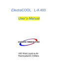
ElectraCOOL L-A 550
550-Watt Rack Mountable
Thermoelectric Chiller
User Manual
For Information Call
1 800-250-2920
One Tara Boulevard
Nashua, NH 03062 USA
international Inquiries (603) 888-2467
electracool.com
rev 7/03
ElectraCOOL LA550 Chiller
PART 1
1.0 Introduction
1
2.0 Specifications
1
3.0 Installation
2
3.1 Mechanical Installation .................................................................................................................2
3.2 Plumbing Installation.....................................................................................................................2
3.3 Electrical Installation .....................................................................................................................3
3.4 Air Considerations .........................................................................................................................4
4.0 Start Up
4
4.1 System Check ................................................................................................................................4
4.2 Coolant Fill......................................................................................................................................5
4.3 Start-up ...........................................................................................................................................5
5.0 Operation
8
5.1 Simple Operation..........................................................................................................................8
5.2 Advanced Operation.....................................................................................................................9
5.3 Alarms ..........................................................................................................................................13
5.4 Auto-tuning...................................................................................................................................13
5.5 Manual Tuning ............................................................................................................................13
6.0 System Alarms/Troubleshooting
14
7.0 Repair and Maintenance
15
7.1 Coolant Draining Procedure ......................................................................................................16
7.2 Fuse Replacement......................................................................................................................16
7.3 Filter Replacement Procedure...................................................................................................16
7.4 Pump Replacement Procedure.................................................................................................17
7.5 Fan Replacement Procedure.....................................................................................................17
7.6 RTD Replacement Procedure ...................................................................................................17
7.7 Flow Switch Replacement Procedure .......................................................................................18
7.8 Temperature Controller Replacement Procedure ..................................................................18
For Information Call
One Tara Boulevard
Nashua, NH 03062 USA
1 800-250-2920
electracool.com
international Inquiries (603) 888-2467
rev 7/03
ElectraCOOL LA550 Chiller
7.9 Thermoelectric Power Supply Replacement Procedure........................................................19
8.0 Spare Parts List
20
Appendix 1 Schematics
21
For the complete guide to using this connection system visit:
23
23
http://www.johnguest.com/plumb_pg1.shtm
23
Technical Support
Our Warranty Policy
24
25
MSDS for Coolant: Part 2
26
Symbols Used on the ElectraCOOL LA 550 Chiller
Read the MSDS for the coolant used and follow all safety precautions
listed in the MSDS prior to removing coolant tubes or opening the fill
cap as this could result in contact with the coolant inside.
Caution! Risk of electric shock. Disconnect main DC power prior to
servicing. This includes changing a fuse or opening the cover for any
reason. Even though the input DC voltage is under 42 VDC, the high
current levels used are a potentially serious hazard.
CAUTION
• Never store or operate the ElectraCOOL LA 550 Chiller at ambient
temperatures over 60 °C or below –20 °C.
• Never attempt to operate the chiller without coolant as damage to the
pump may occur.
• Never ship the chiller with liquid inside as freezing temperatures may be
encountered that would damage the unit or spillage may occur damaging
the chiller and/or items it’s packaging makes contact with. PLEASE drain
and air flush prior to packaging for shipment.
• Never operate the coolant within 5°C of its freezing point.
For Information Call
One Tara Boulevard
Nashua, NH 03062 USA
1 800-250-2920
electracool.com
international Inquiries (603) 888-2467
rev 7/03
ElectraCOOL LA550 Chiller
1.0 Introduction
The ElectraCOOL LA550 Chiller is a thermoelectric temperature control system
designed to meet RTCA DO-160D requirements for use in aircraft. The chiller
circulates 1.2 gpm of constant temperature coolant for controlling laser package
temperatures and other temperature sensitive systems. It does not use Freon
or any other replacement gas. From conception, this chiller has been designed
for long life and ease of use. The internal thermoelectric modules have lifetimes
greater than 200,000 hours.
2.0 Specifications
Process Fluid Type:
Ambient Air Operating Range:
Cooling Capacity @25°C with
25°C Ambient Air :
Control Accuracy:
Storage Temperature Range
Humidity
Set-point Range:
Temperature probe:
Process Pump Capacity :
Process Fluid Connections:
Input Power :
Input Voltage Range:
Abnormal Input Voltage
System Proof Pressure :
Process Fluid Reservoir:
Dimensions:
Weight :
Water, Ethylene Glycol 50/50
5°C to 40°C
600W
±0.5°C
-20°C to 60°C
95% minimum non condensing
-10°C to +50°C
100Ω Platinum RTD, 3 Wire
1.2 gpm @ 35 psi
3/8” DESO Quick Disconnect,
Minimal Spillage on 90° elbow for
space constraint
Parker FS-371-6FP inlet (Female)
Parker FS-372-6FP outlet (Male)
Include mating connectors (3/8”NPT
Female ends)
27.5 VDC Nominal @ 1000W
22 to 30.3VDC
20.5 to 32.5 VDC for 5 min
100 psi
1 Liters
19” rack mount , 14” high, 16.5”
deep
65 lbs
1
For Information Call
One Tara Boulevard
Nashua, NH 03062 USA
1 800-250-2920
electracool. com
international Inquiries (603) 888-2467
rev 7/03
ElectraCOOL LA550 Chiller
3.0 Installation
3.1 Mechanical Installation
The ElectraCOOL LA 550 Chiller is designed to fit into an EIA alternate 19”
electronics rack. The chiller is size 8U, or 13.969” tall and 16.5” deep. Support
rails are required for mounting. Install the chiller into the electronics rack as
follows:
Ensure that support rails have been installed in the rack unit. Remove the
chiller unit and accessory parts from the packaging. Install the chiller into the
rack with eight 10-32 screws and appropriate washers. The chiller rack mount is
designed for the EIA Alternate standard and will fit alternate and universal
spacing.
3.2 Plumbing Installation
See Figure 1. The accessories for the chiller include:
•
•
•
•
DESO quick disconnects with right angle adapters
Mating DESO fittings with 3/8” FNPT ports
Drain valve with plug
Coolant fill port and plug
Install the male DESO quick disconnect onto the Coolant Outlet using the 3/8”
Swagelok right angle adapter included. Turn nut until finger tight, position fitting
in orientation needed then tighten nut which a wrench as per Swagelok
retightening instructions included in section 9 (use a backing wrench to hold the
fitting from rotating).
Install the female DESO quick disconnect onto the Coolant Inlet in a similar
manner.
Install the Drain valve with plug installed onto the Coolant Drain fitting and
tighten as per Swagelok retightening instructions.
Install fill port elbow into Coolant Fill 3/8” FNPT port. Use Teflon tape or thread
sealant on the threads, turn until tight and elbow is facing up.
Connect coolant lines with mating connectors to the coolant inlet and outlet.
2
For Information Call
One Tara Boulevard
Nashua, NH 03062 USA
1 800-250-2920
electracool. com
international Inquiries (603) 888-2467
rev 7/03
ElectraCOOL LA550 Chiller
3.3 Electrical Installation
See Figure 1. All electrical connections are located at the rear of the unit for
ease of access.
DC Power: Connect 28 VDC, 50-amp service via the 4-pin MS3470W14-4P
connector as follows:
Pin
Pin
Pin
Pin
A
24 VDC (+)
B 24 VDC (+)
C
24 VDC (-)
D 24 VDC (-)
Remote RTD/Signals: The chiller comes with a laser interlock signal and
connections for a remote RTD temperature sensor via the 10pin MS3470W12-10S as follows:
Pin
Pin
Pin
Pin
Pin
Pin
Pin
Pin
Pin
Pin
A Laser Interlock (+)
B Laser Interlock common
C Laser Interlock Shield
D Spare
E
Spare
F Chassis Shield
G Remote RTD Shield
H Remote RTD (-)
I Remote RTD (+)
J Remote RTD Ground
The laser interlock is a normally closed dry contact that opens in the event of a
fault in the chiller.
The Remote RTD can replace the internal RTD used by the temperature controller
for controlling coolant temperature. Use of the internal RTD is recommended
due to its proximity to the thermoelectric heating/cooling engine and the
correspondingly shorter temperature response lag time. Use of the remote RTD
requires opening the enclosure and switching RTD connectors inside the
electronics box and requires tuning of the PID constants. (See section 5.5 for
instructions on tuning.)
3
For Information Call
One Tara Boulevard
Nashua, NH 03062 USA
1 800-250-2920
electracool. com
international Inquiries (603) 888-2467
rev 7/03
ElectraCOOL LA550 Chiller
Install the remote RTD as follows:
(Use an ESD wrist strap during this procedure to ensure the electronics will not be
damaged)
1.
2.
3.
4.
5.
Ensure chiller power is turned off
Disconnect chiller main power connector
Remove the six screws holding the controller panel on the front face
Gently pull the panel out
Locate the internal RTD connector (White in line connector) in the wire
harness behind the controller panel
6. Locate the remote RTD connector(white with three contacts sticking out) in
the upper left hand corner of the opening on top of the mesh cover
7. Disconnect the internal RTD
8. Connect the remote RTD connector
9. Reinstall the controller panel and fasten with the six screws and Loctite 242.
10. Plug in main power and turn the chiller on.
11. Press the start button to set the chiller to an idle mode
12. Perform a closed loop tuning and enter the new PID parameters.
3.4 Air Considerations
The main air inlet is located on the front panel and the outlet on the rear panel.
Normal airflow is approximately 320 cfm. Restricting airflow into or out of the
chiller will impair performance. At least 6 inches of clearance is required on each
side to ensure adequate airflow.
Cooling air for the electronics enters from the right side panel. At least ½” inch
of clearance is required on this side to ensure adequate cooling of the Chiller’s
electronics.
4.0 Start Up
4.1 System Check
Perform the following systems check prior to operating the chiller for the first
time, after maintenance has been performed on the Chiller or its exterior
plumbing, or after a prolonged period of non-use.
1) Verify coolant lines are properly connected to the rear pipe fittings and the
laser assembly.
2) Verify all electrical connections are made: DC Power and Interlock/Remote
RTD Signals
3) Check that no obstructions are located within 6” of the main air inlet and
outlet
4
For Information Call
One Tara Boulevard
Nashua, NH 03062 USA
1 800-250-2920
electracool. com
international Inquiries (603) 888-2467
rev 7/03
ElectraCOOL LA550 Chiller
4.2 Coolant Fill
See Figure 1. The ElectraCOOL LA 550 Chiller is designed to operate with a
50/50 mixture of water and ethylene glycol (WEG). Always verify the proper
mixture is being used prior to filling the chiller. Fill the chiller as follows:
1.
2.
3.
4.
5.
6.
7.
8.
9.
10.
11.
12.
13.
Ensure the drain valve is closed and the drain plug is installed
Remove fill port plug
Place the spout of the fill bottle into the open fill port
Gently squeeze and release the fill bottle repeatedly in one to two sec
intervals. This method will reduce the possibility of overflowing the fill
port. (note: the tank has a small volume and can fill rather quickly. When
liquid no longer drains from the fill port the tank is full and liquid must
be pumped into the rest of the system.)
Fill until the liquid starts to pool in the fill port,
Replace fill port plug.
Turn chiller on with main circuit breaker (Pump and thermoelectrics will
automatically start.)
Let pump run for 3 sec then press the START button to stop the pump off
(note: Flow fail may occur if the pump runs for 5 sec and no flow is
detected, this requires a power cycle to clear)
If “TANK LEVEL LOW” alarm appears (alternating with main display every
sec) then turn off chiller and repeat steps 2 through 9 until the “TANK
LEVEL LOW” indication no longer appears. This should take 2 ½ to 3 full
bottles.
Allow the chiller to run for a few minutes in order to de-bubble the
system.
Add fluid to the fill port while the pump is running until it starts to pool
in the fill port.
Wrap the fill plug with 2 wraps of Teflon tape and reinstall.
Push start button to stop pump and thermoelectrics, and go to idle mode
if desired.
4.3 Start-up
See figures 2 and 4. Once the system check and coolant fill have been
completed, start -up the ElectraCOOL LA 550 Chiller as follows:
1) Turn on DC power to the chiller.
2) Turn on the circuit breaker located on the front panel.
3) If a tank level low warning is displayed, check for leaks and follow the
instructions on adding coolant in section 4.2.
4) If necessary, adjust the control temperature as desired by pressing the UP
and DOWN keys. Press the START key after making a set point change.
5
For Information Call
One Tara Boulevard
Nashua, NH 03062 USA
1 800-250-2920
electracool. com
international Inquiries (603) 888-2467
rev 7/03
ElectraCOOL LA550 Chiller
Figure 1:
6
For Information Call
One Tara Boulevard
Nashua, NH 03062 USA
1 800-250-2920
electracool. com
international Inquiries (603) 888-2467
rev 7/03
ElectraCOOL LA550 Chiller
Figure 2:
Figure 3:
7
For Information Call
One Tara Boulevard
Nashua, NH 03062 USA
1 800-250-2920
electracool. com
international Inquiries (603) 888-2467
rev 7/03
ElectraCOOL LA550 Chiller
5.0 Operation
The ElectraCOOL LA 550 Chiller is operated via the control panel located on the
front panel. The control panel has a 16-character LCD display and four input
keys: UP, DOWN, ENTER, and START. These keys work as follows:
Key
UP
DOWN
ENTER
ENTER
START
START
Action
Pressing the UP key raises the parameter value displayed.
Pressing the DOWN key lowers the parameter value displayed
Pressing the ENTER key momentarily enters the parameter changed.
Pressing and holding the ENTER key for 3 seconds changes the LCD
display menu.
Pressing the START key turns on temperature control.
Pressing the START key while the chiller is operating turns off
temperature control.
5.1 Simple Operation
The ElectraCOOL LA 550 Chiller comes with preset operating parameters that
will work well for most applications. If temperature control at a new
temperature is desired, follow the steps below:
1) Turn on ElectraCOOL LA 550 Chiller and wait for display to read TEMP.
2) Press the UP or DOWN keys to change SETTEMP 1 to the desired set point.
3) Press the START key.
The ElectraCOOL LA 550 Chiller will now control to the new set point
temperature. Figure 5 shows the cooling capacity measured at ADVANCED
THERMOELECTRIC at various set point temperatures for a 23°C ambient air
temperature.
8
For Information Call
One Tara Boulevard
Nashua, NH 03062 USA
1 800-250-2920
electracool. com
international Inquiries (603) 888-2467
rev 7/03
ElectraCOOL LA550 Chiller
5.2 Advanced Operation
The ElectraCOOL LA 550 Chiller controller has three menus: the Status Menu,
the Temperature Input Menu and the Parameter Input Menu. The Status Menu
shows the chiller operating status and current temperature of fluid leaving the
chiller. The Status Menu also allows input of new coolant temperature set
points when the cycling feature is off. The Temperature Input Menu allows input
of set-point temperatures, soak times, number of cycles if cycling between two
temperatures, and an alarm temperature. The Parameter Input Menu allows
input of the temperature units, the time units for soak times, the PID
parameters and the auto-tune function.
The PID parameters have been preset at the factory for most applications. If,
however, temperature control in not sufficiently accurate or if overshoot is
excessive, the PID parameters may be modified. Unless the user is well versed
in PID theory, we recommend calling ADVANCED THERMOELECTRIC technical
support group for assistance.
NOTE: If continuous control at one set-point temperature is desired, set # OF
CYCLES to zero.
9
For Information Call
One Tara Boulevard
Nashua, NH 03062 USA
1 800-250-2920
electracool. com
international Inquiries (603) 888-2467
rev 7/03
ElectraCOOL LA550 Chiller
Menu Structure
Status Menu --------> Temperature Input Menu --------> Parameter Input Menu ------->Status Menu
↓
↓
Press up or down
SETTEMP 1
TEMPUNIT
key to change
↓
↓
SETTEMP 1
SETTIME1
TIMEUNIT
Press start to begin
↓
↓
controlling at new
SETTEMP 2
AUTOTUNE
SETTEMP 1
↓
↓
SETTIME 2
P1 HEAT
↓
↓
# OF CYCLES
I1 HEAT
↓
↓
ALARM TEMP
D1 HEAT
↓
P2 COOL
↓
I2 COOL
↓
D2 COOL
↓
MAX PWM
Press ENTER key once to scroll between menu items (↓).
Press and hold ENTER key for 3 seconds to scroll between menus (--------->).
Note: If the user enters the temperature input or the parameter input menus
and does not press a key for 30 seconds the display will revert back to the
Status menu.
Status Menu: The status menu displays the chiller operating status and coolant
temperature. The chiller operating mode is shown in the display’s first
character: (See Figure 4)
10
For Information Call
One Tara Boulevard
Nashua, NH 03062 USA
1 800-250-2920
electracool. com
international Inquiries (603) 888-2467
rev 7/03
ElectraCOOL LA550 Chiller
* = Standby mode, no temperature control
+ = Heating mode with temperature control within deviation band
- = Cooling mode with temperature control within deviation band
< Heating mode with coolant temperature below deviation band limit.
> Cooling mode with coolant temperature above deviation band limit.
A= Auto-tune in progress
Notes: 1) The coolant outlet temperature is shown after TEMP in °C or °F.
2) The deviation band limits are preset at +/- 5°C from set point.
3) Pressing the UP or DOWN keys with # of cycles set to zero will change
the set point temperature upon pressing the START key.
Temperature Input Menu: The temperature input menu allows input of operating
temperatures, soak times, number of cycles desired, and an optional alarm
temperature. Note: If # of cycles is set to zero, only TEMP 1 and ALARM TEMP
will be used.
SETTEMP1 = Set-point of first control temperature. If # OF CYCLES is set to
zero, this is the control temperature.
SETTIME1 = Soak time at temperature 1. Not used if # OF CYCLES is set to
zero.
SETTEMP2= Set-point of second control temperature. Not used if # OF CYCLES
is set to zero.
SETTIME2 = Soak time at temperature 2. Not used if # OF CYCLES is set to
zero.
# OF CYCLES = Number of cycles between temperature 1 and temperature 2, 0999 cycles. If set to zero, then the ElectraCOOL LA 550 Chiller will
continuously control at temperature 1.
11
For Information Call
One Tara Boulevard
Nashua, NH 03062 USA
1 800-250-2920
electracool. com
international Inquiries (603) 888-2467
rev 7/03
ElectraCOOL LA550 Chiller
Parameter Input Menu: The parameter input menu allows input of temperature
units, time units, PID parameters, and turns on or off auto-tune.
TEMPUNIT = °C or °F
TIMEUNIT = s: seconds, m: minutes, h: hours
AUTOTUNE = on/off. On turns on auto-tune where the controller determines PID
parameters. Once PID parameters have been determined
AUTOTUNE reads off.
P1 HEAT = Proportional band for heating, 0-99.9 °C or °F.
Factory Default
Value: 4.4
I1 HEAT = Integral term for heating, 0-999 seconds
Factory Default
Value: 22
D2 HEAT = Derivative term for heating, 0-999 seconds
Factory Default
Value: 2
P2 COOL = Proportional band for cooling, 0-99.9 °C or °F
Factory Default
Value: 2.4
I2 COOL = Integral term for cooling, 0-999 seconds
Factory Default
Value: 22
D2 COOL = Derivative term for cooling, 0-999 seconds
Factory Default
Value: 2
MAX PWM = Maximum voltage delivered to the thermoelectric modules. Setpoint range:16-24 VDC Higher values increase the maximum cooling
capacity of the chiller, but also increase the current draw. See figure
6 for cooling capacity vs. thermoelectric module voltage. The Factory
Default Setting: 21.0 VDC
Figure 6: Input Current with 300 Watt Load
Under Various Operating Conditions
12
For Information Call
One Tara Boulevard
Nashua, NH 03062 USA
1 800-250-2920
electracool. com
international Inquiries (603) 888-2467
rev 7/03
ElectraCOOL LA550 Chiller
5.3 Alarms
The ElectraCOOL LA 550 Chiller has one normally closed dry-contact for system
failure. A list of system failures causing the system alarm contact to open can
be found in Section 6. In the event of a system failure, the dry contact will open
and the alarm type will be shown on the front display.
5.4 Auto-tuning
The ElectraCOOL LA 550 Chiller comes with an automatic tuning (auto-tune)
feature. Changing the PID parameters is normally not recommended unless the
RTD probe is moved to a new location. However, the controller can calculate
new PID parameters via the auto-tune function. The following keystrokes
initiate the auto-tune function:
1) Press and hold the Enter key until the Status Menu changes to the
Temperature Input menu.
2) Press and hold the Enter key again until the Temperature Input menu changes
to the Parameter Input menu.
3) Press the Enter key three times. The display should read AUTOTUNE off.
4) Press the Up key to change off to on.
5) Press and hold the Enter key until the parameter input menu returns to the
Status Display.
6) Press the Start key once. The left most display character will show the letter
A until the auto-tune is complete. The ElectraCOOL LA 550 Chiller will then
begin controlling at the set point temperature.
5.5 Manual Tuning
Changing the PID parameters is normally not recommended unless a remote RTD
probe is used. If the remote RTD is used, ADVANCED THERMOELECTRIC
recommends the closed-loop “Ziegler Nichols” method for manually tuning the
controller. The method consists of three steps:
1) Turn off both the integral and derivative terms for heating and cooling by
setting I1, I2, D1,and D2 to zero.
2) Set proportional band to 50 °C. Begin controlling the process at the desired
set-point temperature. Look for a small sustained oscillation in the coolant
temperature. Observe the status menu operating mode character and note if
system is heating(+) or cooling (-). If no oscillation occurs, lower the
proportional band in 50% increments until a small oscillation occurs. Write
down this proportional band setting (P)
3) Measure the “Natural Frequency” (t) of the system in seconds. This is the
time required for the temperature oscillation to cycle from one maximum
temperature to the next maximum temperature.
13
For Information Call
One Tara Boulevard
Nashua, NH 03062 USA
1 800-250-2920
electracool. com
international Inquiries (603) 888-2467
rev 7/03
ElectraCOOL LA550 Chiller
Now set the controller input parameters as follows:
P1 HEAT = 2*P if system was heating in step 2.
P1 HEAT = 4*P if system was cooling in step 2.
I1 HEAT = 1.2*t
D1 HEAT = t/8
P2 COOL = P if system was heating in step 2.
P2 COOL = 2*P if system was cooling in step 2.
I2 COOL = 1.2*t
D2 COOL = t/8
6.0 System Alarms/Troubleshooting
The ElectraCOOL LA 550 Chiller has four system alarms that when triggered will
show on the display. When an alarm is displayed the system will not attempt
to heat or cool the coolant and the RED status light will illuminate. The P&ID is
included at the end of this section for your reference.
Tank Level Low:
Liquid reservoir level is too low. This is a warning only
and will not trigger the system failure alarm. It will illuminate the
RED status light. Unless filling for the first time, check all
outside plumbing lines for leaks. Once all leaks are sealed, follow
the procedure in section 4.2 and add more coolant until the alarm
disappears.
Warning! Always disconnect the DC power cord before
opening the ElectraCOOL LA 550 Chiller cover as electrical
shock hazards exist inside.
RTD Open
/Shorted:
Fan Fail:
The temperature sensor has failed or its connector has come
loose.
Turn off the ElectraCOOL LA 550 Chiller and disconnect the DC
power cord. Open the controller panel and check that the 5-pin
connector is firmly attached to the controller board and there are
no loose wires in the white miniature RTD connector located
inside. If both are correct, replace the internal RTD as per the
procedure in section 7.5.
Fan is supplying insufficient air to cool the thermoelectrics. Either
one or both of the fans have failed or the airflow into or out of
the system is blocked. Check that the front and rear air inlet and
outlet gratings are not blocked. The ElectraCOOL LA 550 Chiller
requires at least 6 inches of clearance around these gratings. If
airflow is not blocked, contact ADVANCED THERMOELECTRIC for
an RMA number to return the unit for fan replacement.
14
For Information Call
One Tara Boulevard
Nashua, NH 03062 USA
1 800-250-2920
electracool. com
international Inquiries (603) 888-2467
rev 7/03
ElectraCOOL LA550 Chiller
Flow Fail:
The coolant flow switch has tripped, indicating coolant flow has
dropped below 0.5 gpm. Turn off the ElectraCOOL LA 550 Chiller
and disconnect the DC power cord. Verify that no kinks or
blockages exist in plumbing between the chiller and object having
the temperature controlled. If no coolant flow blockages exist,
replace the coolant filter as per the procedure in section 7.2. If
this does not solve the problem, replace the pump as per the
procedure in section 7.4.
No Display:
If the liquid crystal display does not illuminate upon turning on
the ElectraCOOL LA 550 Laser Chiller, either the 14-pin connector
to the controller board has come loose or the LCD display has
failed. Turn off the ElectraCOOL LA 550 Chiller and disconnect
the DC power cord. Open the controller panel and check that the
14-pin connector is firmly attached to the controller board. If the
connector is firmly attached, replace the temperature controller
as per the procedure in section 7.8
Temperature If no other alarms are present, poor temperature control indicates
Control Poor: the heat load is too great for the chiller, the TE cooling/heating
engine is not receiving power or has failed, or the PID constants
have been corrupted. First check the PID constant values shown
section 5.2 match the factory defaults. If not, change the values
to the default values. Otherwise, contact ADVANCED
THERMOELECTRIC for technical support.
Important:
The tank level low alarm will automatically reset when the tank is
filled. The RTD, Fan and Pump failure alarms will not reset until
the system power is turned off.
7.0 Repair and Maintenance
The ElectraCOOL LA 550 Chiller is designed with thermoelectric devices for
heating and cooling to minimize moving parts, maintenance, and repairs. Listed
below are procedures for maintaining and repairing the chiller. (Refer to figures
5-X for exploded views of the chiller and its sub-components.) Should you have
any questions about these procedures, call ADVANCED THERMOELECTRIC for
assistance.
Preventative Maintenance Schedule:
Fans/Air Heat Sinks: Vacuum off dust annually
Coolant Filter: Check semi-annually, replace annually
Pump: Rebuild after 16,000 hours of operation
15
For Information Call
One Tara Boulevard
Nashua, NH 03062 USA
1 800-250-2920
electracool. com
international Inquiries (603) 888-2467
rev 7/03
ElectraCOOL LA550 Chiller
7.1 Coolant Draining Procedure
1. Remove plug from drain cock (see figure 1 and John Guest insert for details)
2. Connect ¼” OD hose to push on connector on drain cock and place other end
in a suitable container
3. Remove fill port plug
4. Open drain-cock
5. Let drain for 10 minutes
6. Remove filter access panel
7. Remove screw holding the filter support strap
8. Loosen and remove the filter housing (it will be full of fluid) pour fluid into
the container
7.2 Fuse Replacement
1.
2.
3.
4.
5.
6.
7.
8.
Ensure chiller power is turned off and chiller main power is unplugged
Remove chiller from the rack
Remove the 9 screws holding the top cover and remove the cover
Remove the perforated electronics enclosure cover
Remove fuse with a fuse puller
Replace fuse
Reinstall the perforated cover.
Close top cover and fasten with the 9 screws removed in step 3 (use Loctite
242)
9. Reinstall chiller and check operation
7.3 Filter Replacement Procedure
1.
2.
3.
4.
5.
6.
7.
8.
9.
Drain system as per draining procedure
Remove filter access panel (see figure 1)
Remove screw holding the pump support strap
Loosen and remove the filter housing (it will be full of fluid) pour fluid into a
suitable container.
Inspect the filter for particulate and clean if necessary.
Reinstall filter and housing
Reattach filter support strap
Close filter access panel
Follow fill procedure to refill the system
16
For Information Call
One Tara Boulevard
Nashua, NH 03062 USA
1 800-250-2920
electracool. com
international Inquiries (603) 888-2467
rev 7/03
ElectraCOOL LA550 Chiller
7.4 Pump Replacement Procedure
(note: this procedure requires the chiller be removed from the rack)
1. Drain system as per draining procedure
2. Open pump access panel (see figure 3)
3. Remove the pump electrical connector from the bulkhead on the upper right of
the pump access hole
4. Loosen but do not remove the four screws holding the pump mounting bracket
to the vibration isolation mounts
5. Loosen and remove the 3/8” Swagelok connection on the outlet side of the
pump (towards front)
6. Loosen 3/8” Swagelok connection on the inlet side of the pump (note: some
residual fluid may still be in the line)
7. Remove the four mounting screws
8. Remove the Swagelok connection
9. Remove pump through the pump access hole
10. Install new pump assembly though the pump access hole
11. Remake both Swagelok fittings hand tight only
12. Install the four mounting screws with Loctite 242
13. Tighten the Swagelok fittings with a wrench (note: use a backing wrench
on the threaded end of the fitting going into the pump, and follow Swagelok
recommended retightening guidelines)
14. Reinstall Pump electrical connector
15. Close access panel
16. Follow fill procedure to refill system
7.5 Fan Replacement Procedure
The two 6” cooling fans are not field replaceable. Contact ADVANCED
THERMOELECTRIC for an RMA number to return the unit for fan replacement.
7.6 RTD Replacement Procedure
1.
2.
3.
4.
5.
Drain system using drain procedure
Open Filter access cover and remove filter and strap (see figure 1)
Disconnect internal signal connector (to the left side of the filter location)
Open the back shell of the connector
Remove pins with the pin removal tool
E
F
G
Red
White
Red
RTD RTD +
RTD Ground
6. Install new RTD wires into E, F, and G.
7. Reassemble connector and back shell and reconnect
17
For Information Call
One Tara Boulevard
Nashua, NH 03062 USA
1 800-250-2920
electracool. com
international Inquiries (603) 888-2467
rev 7/03
ElectraCOOL LA550 Chiller
8. Locate the RTD sensor to the right of the drain cock just inside the chassis
9. Use proper wrenches to loosen and remove the old RTD at the stainless steel
¼” Swagelok nut from the plumbing.
10. Insert new pre-swaged RTD assembly and tighten per Swagelok
retightening instructions.
11. Reinstall filter and strap
12. Fill system using fill procedure and check for leaks
13. Verify RTD is functioning correctly
7.7 Flow Switch Replacement Procedure
1.
2.
3.
4.
5.
6.
7.
8.
9.
Drain system using drain procedure
Open Filter access cover and remove filter and strap (see figure 1)
Disconnect internal signal connector (to the left side of the filter location)
Open the back shell of the connector
Remove pin C with the pin removal tool
Remove signal ground wire from the signal ground terminal strip
Install new wire in pin C with pin insertion tool
Install new wire on signal ground terminal strip
Reassemble connector with shield wire connected to the back shell and
reconnect
10. Use proper wrenches to loosen and remove the old flow switch at the 3/8”
Swagelok fittings, taking note of the flow direction. (continued)
11. Install the new flow switch and tighten the Swagelok fittings following the
Swagelok retightening instructions (see attachment in section 9).
12. Reinstall the filter and strap
13. Fill system using fill procedure and check for leaks
7.8 Temperature Controller Replacement Procedure
(Use an ESD wrist strap during this procedure to ensure the electronics will not
be damaged)
1. Ensure chiller power is turned off and chiller main power is unplugged
2. Remove the Decal covering the Control buttons and LCD Display (see figure 2)
3. Remove the six screws holding the controller panel on the front face
4. Gently pull the panel out
5. Carefully note the location of each connector and remove all electrical
connectors from the controller board
6. Loosen and remove the five screws that secure the board to the panel
7. Remove the old controller
8. Install new controller and fasten with the 5 mounting screws (use Loctite
242)
9. Reinstall all electrical connectors in their proper location.
10. Reinstall the controller panel and fasten with the six screws and Loctite
242.
11. Apply new decal over buttons and LCD Display
12. Plug in main power and turn the chiller on.
18
For Information Call
One Tara Boulevard
Nashua, NH 03062 USA
1 800-250-2920
electracool. com
international Inquiries (603) 888-2467
rev 7/03
ElectraCOOL LA550 Chiller
13.
14.
Press the start button to set the chiller to an idle mode
Verify PID settings are correct
7.9 Thermoelectric Power Supply Replacement Procedure
(not recommended as a field procedure)
1.
2.
3.
4.
5.
Ensure chiller power is turned off and chiller main power is unplugged
Remove chiller from the rack
Remove the 9 screws holding the top cover and remove the cover
Remove interior perforated cover
Carefully note the location of each connector and remove all electrical
connectors from the power supply board (see figure 7)
6. Loosen and remove all screws holding the right side bracket (the one with
wire grommets and the fuse) From the outside of the chassis and the bottom
of the electronics box.
7. Open the pump access panel
8. Loosen but do not remove the four 8-32 socket head cap screws (do not
remove the 5 pan head Philips holding the board to the heat sink) holding the
power supply assembly and using allen wrench and socket wrench to hold the
nut below the electronics box (access though the pump access panel)
Note: you will have to move the right side bracket to gain access to two of
the mounting screws.
9. Install the new power supply assembly using the four socket head cap screws
and locknuts removed in step 8
10. Reconnect all electrical connectors
11. Secure the right side bracket
12. Close and fasten the pump access panel
13. Reinstall the interior perforated cover
14. Close top cover and fasten with the 9 screws removed in step 3 (use
Loctite 242)
15. Reinstall chiller and check operation
19
For Information Call
One Tara Boulevard
Nashua, NH 03062 USA
1 800-250-2920
electracool. com
international Inquiries (603) 888-2467
rev 7/03
ElectraCOOL LA550 Chiller
Figure 7
8.0 Spare Parts List
Description
Fuse
Pump
Fan
RTD
Flow Switch
Temperature Controller
TE Power Supply
Level Switch
DC-DC Converter
Input Module
ADVANCED
THERMOELECTRIC Part
Number
20-22522-1
36-22418-1
28-22425-5
24-22521-1
24-22430-1
26-22200-3
18-22419-1
24-22421-1
20-22517-1
20-22518-1
20
For Information Call
One Tara Boulevard
Nashua, NH 03062 USA
1 800-250-2920
electracool. com
international Inquiries (603) 888-2467
rev 7/03
ElectraCOOL LA550 Chiller
Appendix 1 Schematics
21
For Information Call
One Tara Boulevard
Nashua, NH 03062 USA
1 800-250-2920
electracool. com
international Inquiries (603) 888-2467
rev 7/03
ElectraCOOL LA550 Chiller
Appendix 2 Schematics
This page intentionally left blank for online manual. Pease contact us to receive
this diagram or to request a copy of our nondisclosure agreement.
22
For Information Call
One Tara Boulevard
Nashua, NH 03062 USA
1 800-250-2920
electracool. com
international Inquiries (603) 888-2467
rev 7/03
ElectraCOOL LA550 Chiller
For the complete guide to using this connection system visit:
http://www.johnguest.com/plumb_pg1.shtm
23
For Information Call
One Tara Boulevard
Nashua, NH 03062 USA
1 800-250-2920
electracool. com
international Inquiries (603) 888-2467
rev 7/03
ElectraCOOL LA550 Chiller
Technical Support
Delighting our customers is our highest priority. Please contact us immediately for technical
assistance whenever you have questions or concerns. We can be reached in North America TollFree at 1 (800) 250-2920, by e-mail at: [email protected] or by using the contact numbers
at the bottom of each page.
Our Warranty Policy
Your satisfaction is important to us. ADVANCED THERMOELECTRIC
provides a one year, full parts and labor warranty on ElectraCOOL
chillers.
Malfunctioning products should be returned to ADVANCED THERMOELECTRIC by
the method selected when obtaining an RMA as described below. ADVANCED
THERMOELECTRIC will provide a Failure Analysis Report to the customer and will
determine if the problem is covered under the warranty.
Warranty Coverage:
Products with defects in components or manufacturing which are reported to
ADVANCED THERMOELECTRIC before the end of the warranty period will be
repaired or replaced at no cost (see below for reporting requirements). The
warranty period begins on the date the product was initially shipped from
ADVANCED THERMOELECTRIC.
The length our warranties is product-specific and depends on the type and planned usage of
the product, but will be specified in the quotation upon which a purchase order is made.
Prototypes are not warranted, but will be repaired/adjusted after original shipment until
they meet the agreed-upon specifications.
Excluded from Warranty:
Excluded from warranty is any damage caused to the product occurring during,
but not limited to, such events as shipment, installation, storage, or usage
occurring during a situation specifically cautioned against or noted in the product
manual.
Specific situations, which invalidate the warranty, include (but are not limited to):
•
•
•
Removing the serial number label.
Any disassembly (partial or complete) of a heat exchanger, which includes removing
the tape on the sides, loosening or removing the bolts, or separating the heat sinks.
Subjecting a heat exchanger to temperatures below the freezing point of the heat
transfer fluid contained inside the unit.
24
For Information Call
One Tara Boulevard
Nashua, NH 03062 USA
1 800-250-2920
electracool. com
international Inquiries (603) 888-2467
rev 7/03
ElectraCOOL LA550 Chiller
•
•
•
•
•
Subjecting a heat exchanger to unfiltered water.
Subjecting any product to temperature, voltage, current, or pressure (internal or
external) greater than that specified in the product manual.
Employing pulse-width-modulated control at less than 1000 Hz.
Operation of a power supply with a non-original enclosure or any replacement
components. As well as voiding the warranty, these actio ns will also void the CE Mark
(Switchback 6600 CE model power supply).
Any actions prohibited in the "Caution" section of the product manual.
Returned Goods Procedure and Reporting Requirements
Before a failed product is returned to the factory, a Returned Materials
Authorization (RMA) number must be obtained from Customer Service at 1 (800)
250-2920 in the US and Canada or at the fax/phone numbers below for
international customers. The date the RMA is requested will be the reporting
date noted and relevant to the warranty. Products, which have received an RMA,
must be received at Advanced Thermoelectric within 30 days or the reporting
date will be moved ahead 30 days and a new 30-day waiting period will begin.
For MSDS Please see Part Two: www.electracool.com/LA550MSDS.pdf
25
For Information Call
One Tara Boulevard
Nashua, NH 03062 USA
1 800-250-2920
electracool. com
international Inquiries (603) 888-2467
rev 7/03