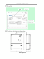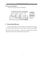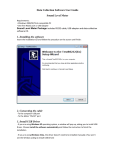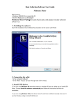
1
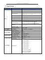
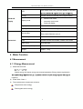
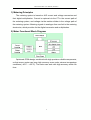
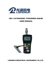
USER MANUAL
DTS541 Three-Phase Energy Meter
(CT type)
Holley Metering Ltd.
www.holleymeter.com
www.formway.com.au
Three-Phase Meter User Manual (Australia)
Contents
1
Introduction ............................................................................................. 3
2
Reference standards ............................................................................. 3
3
Specification ........................................................................................... 4
4
Meter Function ....................................................................................... 5
4.1 Measurement ........................................................................................... 5
4.2.2 Display ................................................................................................... 8
4.2.3 Communication .................................................................................. 10
5
Installation ..............................................................................................11
5.1 Nameplate ...................................................................................................... 12
5.2 Front view, side view and dimensions ....................................................... 12
5.3 Mounting holes and dimensions ................................................................. 13
5.4 Terminal box dimensions ............................................................................. 13
5.5 Connection diagram ...................................................................................... 14
6
Transportation/Storage ....................................................................... 14
2
Three-Phase Meter User Manual (Australia)
1 Introduction
This manual is for the DTS541 CT-connected three-phase energy meter. It
should be used to guide the meter installation, usage, maintenance and for
technical reference.
2 Reference standards
Standard
AS62053.21 - 2005
AS 1284.1-2004
AS 1284.10.2-2006
AS 1284.11-1995
AS 1284.12-1995
AS 62052.11-2005
IEC62052-11
IEC62053-21
IEC62056-21
IEC62056-61
Description
Static Meters for Active Energy Class 1 & 2
Electricity metering - General purpose induction
watthour meters
Electricity metering
Electricity metering Single-phase multifunction
watthour meters
Electricity metering
Electricity metering equipment
Electricity metering equipment (AC) - General
requirements, tests and test conditions - Part 11:
Metering equipment
Electricity metering equipment (AC) - Particular
requirements - Part 21: Static meters for active
energy(classes 1 and 2)
Electricity metering - Data exchange for meter
reading, tariff and load control - Part 21: Direct
local data exchange
Electricity metering - Data exchange for meter
reading, tariff and load control - Part 61: Object
identification system (OBIS)
3
Three-Phase Meter User Manual (Australia)
3 Specification
Item
Sub-item
Parameter
Meter Type
Three Phase Four Wire CT Type
Active Accuracy
Class 1 (IEC 62053-21)
3x 230/400 V
Rated voltage Un
Voltage Range: 0.75Un~1.2Un
Basic
Operating frequency
50Hz
Measuring current (A)
1 (5)A or 5 (15)A
Starting current
0.002In
Pulse constant
10,000imp/kWh
Current circuit power consumption 0.2VA
Power consumption
Voltage circuit power consumption 0.4W/0.8VA
Operating
-25°C ~ +65°C
temperature range
Type Testing
Special Testing
Storage temperature
-40°C ~ +85°C
IEC Standard
IEC 62053-21
Surge immunity test
6kV
impulse voltage strength
12 kV
Over voltage strength
440VAC / 48 hours
Local Comm. Port1
1 Optical port
Local Comm. Protocol1
IEC62056-21 C mode
Active Energy
See 4.1.1
IEC 62052-11
Communication
Voltage of phase A
Voltage of phase B
Voltage of phase C
Current of phase A
Current of phase B
Measurement
Instantaneous
Current of phase C
Total active power
Active power of phase A
Active power of phase B
Active power of phase C
4
Three-Phase Meter User Manual (Australia)
One double-color LED (The LED flashes in red when
LED
Energy
8 digital maximum (decimal point programmable)
Manual scroll mode
LED&LCD
Display mode
Display
Automatic scroll mode
Power-off display
Display interval
See 4.2.2.3
Display contents
Display contents are configurable, see 4.2.2.4
BS Standard
Terminal Box
Entry Cable Diameter (mm): 6
Mechanical
Enclosure protection
IP53
Seal
2 Meter terminal cover seals, 2 Meter cover seals
Meter Case
Polycarbonate
Dimensions(LxWxH)
273mmx170mmx62.5mm
Weight
Approx. 1.2kg
4 Meter Function
4.1 Measurement
4.1.1 Energy Measurement
1)
Measurement mode
(Import energy and export energy are metered separately. Energy data is registered in
negative)
2)
Class index: Class 1
3)
The measurement contents are as below:
Total positive active energy
Total negative active energy
5
Three-Phase Meter User Manual (Australia)
1) Metering Principles
The metering system is based on A/D current and voltage conversion and
their digital multiplication. Current is captured via the CT in the current path of
the metering system, and voltage via the resistor divider in the voltage path of
the metering system. Metering signals in analogue form are fed to the metering
electronics, which provides for the digital conversion and multiplication.
2) Meter Functional Block Diagram
Optimized PCBA design combined with high precision reliable components,
so that ensure meter can keep high accuracy even under extreme temperature
conditions (-40°C ~ +85°C). The meter can work with high accuracy within life
time.
6
Three-Phase Meter User Manual (Australia)
3) Metering Element Design
architecture supporting the 71M6xxx series of isolated current sensing products
offering drastic reduction in component count, immunity to magnetic tampering
and unparalleled reliability. The 71M6545 integrates Teridian's patented Sin-gle
Converter Technology® with a 22-bit delta-sigma ADC, a customizable 32-bit
computation engine (CE) for core metrology functions as well as a user
programmable 8051-compatible application processor (MPU) core with 32K flash
and 3K RAM.
An external host processor may access metrology functions directly through the
SPI interface, or alternatively via the embedded MPU core in applications
requiring metrology data capture, storage and pre-processing within the metrology
subsystem. In addition, the 71M6545 integrates RTC, DIO and a UART.
4.1.2
7
Three-Phase Meter User Manual (Australia)
Instantaneous quantities
The instantaneous quantities are below:
1)
Voltage (Phase A/B/C)
2)
Current (Phase A/B/C)
3)
Total Active Power
4)
Active Power (Phase A/B/C)
4.2.2 Display
4.2.2.1 LCD display
1) The LCD full-screen display is as below:
2)
LCD Symbol
LCD Symbol
Description
Display: for data such as energy, time, date, etc.
Sequence no. of the data displayed in the main
displaying part
Unit of the data displayed in the main displaying part
Daylight saving status (not used in this meter)
Battery low alarm
Communication symbol
On: Meter is communicating
Off: No communication
Alternate (Manual) Scroll Mode
Voltage and current status of each phase
L1/ L2/ L3 on means meter working on the normal
8
Three-Phase Meter User Manual (Australia)
voltage range
L1/ L2/ L3 Flashes means Li phase voltage is
under 0.8*Un or above 1.15*Un
L1/ L2/ L3 off means Li phase voltage is less than
120V, which be regarded as phase loss
Positive energy
Negative energy
Status indicator (not used in this meter)
4.2.2.2 Display mode
1)
Manual scroll display, Automatic scroll display and power-off display;
Display mode can be changed by pressing the button for 3 s. In the mode of
button-pressing display, if there is no pressing for 2 min, the meter will exit the
mode and switch to automatic display.
4.2.2.3 Display interval
1)
Display interval is configurable, 1-99s of each item.
2)
Power-off display mode: the LCD will start automatical display and shut off in 2 min. The
meter can be awakened by pressing the button for 3 s.
4.2.2.4 Display contents
Button & automatic display are independent, display contents are configurable. The
default display item is real time total energy when error occurs in configuration.
Display items
Description
Meter No.
0 88888888
Cumulative
positive
active
negative
active
1 88888888kWh
energy
Cumulative
2 88888888 kWh
energy
Real time voltage of phase A
A 888.8 V
Real time current of phase A
A 888.888 A
Real time power of phase A
A 888.888kW
9
Three-Phase Meter User Manual (Australia)
Real time voltage of phase B
B
888.8 V
Real time current of phase B
B
888.888 A
Real time power of phase B
B
888.888kW
Real time voltage of phase C
C
888.8 V
Real time current of phase C
C
888.888 A
Real time power of phase C
C
888.888kW
Total Power
p
888.888kW
4.2.3 Communication
4.2.3.1 Optical communication
Optical port conforms to IEC62056-21 standard.
The communication protocol is IEC62056-21 C mode.
4.2.3.2 Data that can be read from the meter
Data
Data Format
Unit
Software version
NNNNNNNNNNNNNNNN
Active positive energy
XXXXXXXX
(Number of decimals can be set)
kWh
Read only
Active negative energy
XXXXXXXX
(Number of decimals can be set)
kWh
Read only
Frequency
XX.XXXX
Hz
Read only
Voltage of phase A
XXXX.XX
V
Read only
Voltage of phase B
XXXX.XX
V
Read only
Voltage of phase C
XXXX.XX
V
Read only
Current of phase A
XXX.XX
A
Read only
Current of phase B
XXX.XX
A
Read only
Current of phase C
XXX.XX
A
Read only
Instantaneous active power
XX.XXXX
kW
Read only
Active power of phase A
XX.XXXX
kW
Read only
Active power of phase B
XX.XXXX
kW
Read only
Active power of phase C
XX.XXXX
kW
Read only
10
Note
Read only
Three-Phase Meter User Manual (Australia)
4.2.3.3 Data that can be configured to the meter
Data
Data Format
Note
Meter No.
NNNNNNNN
Read/Write
Password
NNNNNNNN
Read only
No. of integers and decimals
XX
Read/Write
No. of items to be displayed
XX
Read/Write
Interval of display
XX
Read/Write
Items to be displayed
NNNN*12
Read/Write
No. of items to be displayed in manual scroll mode
XX
Read/Write
Items to be displayed in manual scroll mode
NNNN*12
Read/Write
5 Installation
The meter has been inspected and sealed before leaving factory. Before
installation, please check whether the sealing is complete. If so, user may install
the meter. If there is no sealing or the meter has been stored for a long time,
please submit the meter to utility for re-inspection. The meter can be installed at
site after qualified by utility.
The meter shall be installed indoor under well-ventilated and dry place. The
installation environment should be non-caustic and the meter should be protected
from dust, salt and water.
There are two holes in the meter installation base, and use two screws to fix the
meter. The two screws dimension is M6.
11
Three-Phase Meter User Manual (Australia)
5.1 Nameplate
5.2 Front view, side view and dimensions
Meter Dimension
12
Three-Phase Meter User Manual (Australia)
5.3 Mounting holes and dimensions
Installation Dimension
5.4 Terminal box dimensions
13
Three-Phase Meter User Manual (Australia)
5.5 Connection diagram
The connection type conforms to BS standard.
6 Transportation/Storage
The meter shall be kept in the same packing for transportation and storage.
The meter should be stored indoors, in a non-caustic environment and should be
protected from dust, salt and water. There shall be no sharp change in ambient
temperature and the relative humidity shall be less than 85%.
14