1
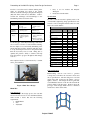
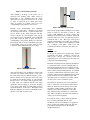
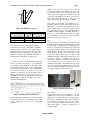
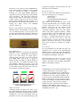
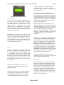
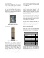
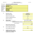
Multi-Disciplinary Senior Design Conference
Kate Gleason College of Engineering
Rochester Institute of Technology
Rochester, New York 14623
Project Number: P10005
DESIGN OF A SEATED BALANCE TRAINING DEVICE
Rochelle Perry
Industrial Engineer
Team Lead
Andy Caola
Computer Engineer
Michael Davies
Mechanical Engineer
Jeff Hansley
Electrical Engineer
Luke Holsen
Mechanical Engineer
NIOSH – National Institute for Occupational Health
and Safety
ABSTRACT
The goal of this project is to develop a balancetraining rehabilitation device for clients of the
Physical Therapy Clinic at Nazareth College. Current
methods of balance training include a standing
Balance Master device and a highly subjective
method of asking the patient to reach to a target held
by the therapist. This new device has been designed
to close the gap between these methods by
providing an objective measure of reaching ability for
primarily wheelchair bound individuals. It will give
the patient illuminated targets at challenging
distances and patterns of reach, and it will be easy to
use for both the therapist and the client
To accomplish the goals of this project two structures
were built for the clients to reach to equipped with
capacitive buttons that will require no force from the
patient to activate, and a game is in place to
illuminate the buttons and give feedback to the
physical therapist. The outer shell of the second
tower is completed, and plans are in place for future
wiring and game design integrating the two towers.
NOMENCLATURE
RGB LED – Red Green Blue Light Emitting Diode.
A semiconductor diode emitting light when
conducting current in red green and blue.
3DSSPP – 3D Static Strength Predication Program
which provides requirements for tasks such as lifts,
presses, pushes, and pulls
JTAG– Joint Test Action Group – Olimex MSP430
JTAG-ISO Programmer- IEEE Standard 1149.1
BACKGROUND
This project aims to develop a balance-training
device to be used by the physical therapy teaching
clinic at Nazareth College. The system will train
clients with disabilities that require them to use a
wheelchair. The device specifically can be used for
clients with spinal cord injuries, multiple sclerosis
(MS), lower extremity amputation, or for anyone
confined to a wheel chair.
At the clinic the physical therapy students are taught
to use various forms of balance training devices to
assess patient ability to move in certain planes and
reach in movements similar to daily tasks. Research
shows that assessing a patient’s ability to balance can
be directly related to their chances of falling. The
clinic uses training to put clients in positions that
could potentially make them fall so they can learn
how to correct the movement on their own.
Copyright © 2010 Rochester Institute of Technology
Proceedings of the Multi-Disciplinary Senior Design Conference
In order to assess the need for balance training at the
clinic, an assessment was made of the current
methods of balance training by the physical therapists
(PT) and clients with various disabilities. Table 1
contains the advantages and disadvantages to the
benchmark products used at the clinic.
• Simple to use
• No set-up
• No storage space
• Objective measure of
patient progress
SMART
Balance
Master [1]
Nintendo Wii • Stimulating Game
Fit [2]
• Too much for clients
with low cognitive
ability
•
Specifications
• No objective measure of
patient progress
• Boring
• Standing only
• Difficult to use
• Frustrates patient
• Nintendo does not
support “Physical
Therapy”
• Difficult to determine
what actually training
To fill the gaps at the Physical therapy clinic there
was a need for a device for seated balance training,
that was simple to use, and visually stimulating to the
patient. The unit would be designed such that once it
is set up the therapist can focus on the patient rather
than the object they need to reach. Being able to
quantify the patient’s ability to balance will help
track the patient’s progress throughout their therapy
sessions.
The completed device as demonstrated by a student
can be seen in Figure 1
Easy to use for Patient and Physical
Therapists
Easily Stored and Portable
•
Table 1: Benchmark Balance Training Devices
Device
Advantages
Disadvantages
PT Hold
Device
Page 2
In order to meet the customer’s primary needs, a list
of measurable engineering design specifications were
created, as well as marginal and ideal values for each.
These are noted in Table 2.
Table 2: Engineering Specifications
Engineering Metrics
Importance
Game response time (to/from
device)
3
Distance from patient to
target
9
Min size patient fit
1
Marginal
Value
Ideal
Value
1000ms
3500ms
24”
45”
36”
40”
Max size patient fit
Height of device
Time to sanitize
3
3
1
50”
40”
45sec
60”
60”
60sec
Withstand “tip test”
Max tilt angle before fall
Time to understand program
Set up time
Time to disassemble
Special confines
3
9
3
9
3
3
5cycles
15deg
5min
2min
1min
3ft2
10cycles
20deg
2.5min
1min
3min
2ft2
Force needed to move
3
15lbs
10lbs
Optical visibility
9
30lumens 35lumens
volume
1
40dB
Button sensitivity
9
.2lbs
.1625lbs
Parts that can be replaced
9
75%
100%
30mins
15mins
.5”
.25”
Time to set up program
3
Showing accuracy of patient
location
9
60dB
Concept Selection
Figure 1 Final Tower Design
PROCESS
Brainstorming sessions were held to generate
concepts that could meet the customer’s needs and
the set specifications. The first design was a tri-fold
design target that would give the patient a grid of
lights to reach to. The design involved a game that
would illuminate buttons on the tri-fold and track the
patient’s ability to hit the targets. Figure 2 shows the
prototype of this design, which was also constructed
and shown to clients at the clinic.
Customer Needs
In order to begin the design process, the customer
needs were first assessed. It was determined that the
clinic needed a device that met the following
requirements:
• Rehabilitative
• Safe
• Adjustable
Project P10005
Figure 2 Tri-Fold Target Design
After building a mock-up of the device out of
cardboard and speaking with clients about its
functionality, it was determined that the design
missed four very important customer needs. It was
too large, it would take up too much space in the
clinic, it wouldn’t be portable, and it was very
overwhelming for the patient to sit in front of.
Through more brainstorming and combining
components of some ideas, a modular tower design
was developed and selected. A selection matrix was
used to decide on this design using the customer
needs as criteria. As seen in Figure 3 the concept
was designed to have a minimum of four individual
posts, that would cut back on space and not be
overwhelming to the patient. Each post could have
three light-up buttons, and be individually wired into
a central USB. The posts would be easily moveable
to allow for simple adjustment and easy storage.
Figure 4 Modified Tower Design
The selected design entailed a multiple tower design
acting as targets for the clients to reach to. The
towers would illuminate in various patterns that
challenge and train the patient’s balance. Ideally the
customer wanted two towers to require the patient to
reach from side to side. The scope of this project
included implementing and testing the technology
behind one tower, which could eventually be turned
into a multiple tower game. Each tower will
eventually be remotely connected to the main tower.
Analysis
Tower Structure
To develop an optimal tower design, many detailed
assessments were made. Similar to choosing the
main project concepts, the customer needs and
engineering specs were considered in choosing each
component of the detailed design.
Figure 3 Initial Tower Design
After demonstrating some preliminary designs with
customers and subject matter experts, it was noted
that some clients may have limited strength to “push”
buttons, and the few feet between each tower would
not track the incremental change at each physical
therapy session. As a result it was suggested to have
a tower with one continuous button tower using
capacitance buttons. Figure 4 shows the modified
tower design with multicolor LED lights between
capacitance buttons on the tower. The lights would
light up in different colors based on the ability for the
patient to reach buttons on the tower.
The main considerations when selecting the material
to construct the tower out of were strength and cost.
The button material needed to be conductive and the
rest of the structure had to be non-conductive so each
button could be activated independently. To simulate
one nearly continuous button, the front of the tower
would be comprised of large aluminum buttons, with
plastic windows between to indicate targets. The
other three sides are constructed out of PVC, which
was the lowest cost non-conductive option.
The deflection calculations were done for the PVC
walls, to ensure the tower would not deflect under a
50lb load, which exceeds the amount of force that
any patient would be putting on the device. The
deflection was found to be .00625” for the entire
three-walled structure and .0697” for a stand-alone
wall. These calculations showed that the deflection
of the tower would be negligible.
To ensure the tower would not easily tip under the
force of clients pushing the buttons, force
calculations were done assuming force is applied at
the top of the tower, middle, and bottom. The free
body diagram in Figure 5 shows the variables
calculated in Table 3.
Proceedings of the Multi-Disciplinary Senior Design Conference
F
While it was proven that the tower could be
ergonomically lifted without handles, for ease of use
for the PT, handles were still designed into the
device. The tower designed to be lifted from the cart
to the floor with handles on each side of the device.
This would reduce the amount of force put on a
single wall if it was only lifted using one handle.
d
h
Figure 5 Modified Tower Design
Table 3: Tower Force Calculations
Location (h)
Distance
Required Force (F)
(d)
Top of Tower (60”)
24.9”
6.6 lbs
Middle of Tower (30”)
12.45”
11.77 lbs
Base of Tower (10”)
4.15”
50.43 lbs
As noted in Table 3, the tower will theoretically
come back to its vertical position until it is pushed
past 24.5, which correlates to a 25” displacement in
the horizontal direction at the top of the tower. The
maximum distance a typical patient can push is 12",
which was calculated using 3DSSPP, and which is
significantly less than the 24" required to tip.
To ensure the safety of the PT while moving the
device, an analysis was done to see if lifting the
tower (32lb) would be damaging to the PT if they had
to perform the task repeatedly. It was assumed that a
cart would be made holds the towers so the maximum
lift would be from the cart to the floor. It was also
assumed as a worst-case scenario that there were no
handles, and that the PT would lift the device a
maximum of 4 times per shift. Figure 6 shows the
NIOSH lifting equation [3] that was used to
determine the lifting index.
Page 4
The position of the handle was calculated for a 5th
percentile female using the Link Length Proportion
Mannequin, to hold the device between hip and
elbow, which is the ergonomically correct position
[4]. The link length tool states that Hip height =
0.530H and Elbow height = 0.630H, where H is
62.05” for a 5th percentile female. The safe region
was determined to be between 32” and 39” lifting
from the storage device to the floor.
Base
The base is made out of 100% recycled rubber. It is
2” thick and 20” long and weighs 20lbs this provides
enough weight to stabilize the tower. The rubber was
chosen as an added safety precaution if a patent falls
before the physical therapist can catch them, the
rubber dampers the fall, rather than having a hard
unsafe object to protrude out of the tower. It also
covers any sharp corners along the edge of the
Aluminum and PVC. The recycled typically used for
road cones, will be very durable and hold up to
repeated use. Each base was cut into two pieces and
set around the base of one of the towers. As
demonstrated in Figure 7, the individual pieces of the
base sits on a flange protruding from the tower giving
the tower increased stability, and each side onto rods
allowing for simple assembly of the device.
Figure 7 Modular Base Designs
Figure 6 NIOSH analysis of lifting task
The lift index was calculated to be below 1, which
means that given the assumptions and correct
posture, lifting the tower is not a dangerous
operation.
Object Touch
Capacitance buttons were determined to be the
optimal button solution based primarily on the fact
that they do not require the user to actually 'push' a
button with a significant amount of force and instead
are activated by proximity. This way, the exercise
can focus directly on balance and range of motion
rather than ability to generate enough force to
activate a button.
Project P10005
The buttons were created by using a B6TS-04LT, a
16-bit micro-controller designed to detect patient
touch by detecting the change in capacitance.
Touching one of the output channels changes the
capacitance between the output and ground with the
body’s capacitance. The touch sensor detects the
change and the output of that channel and changes
voltages, which is detected by the microcontroller.
Figure 8 shows the PCB design that contains one of
the Capacitance Touch Sensor Development Tools
Sensing IC’s which controls four aluminum
“buttons” on the tower.
Because of the wiring involved between the LED’s,
aluminum buttons, and the PCB’s, thorough testing
was of extreme importance. A previous project was
conducted at The Ohio State University, which used
the same chips with the functionality that is desired.
[5]
Figure 8 Solderable Bread Board Design
Target Illumination
RGB LEDs were used as both target and status/state
indicators. A series of RGB LEDs surrounding the
target on two sides denotes the current target, a
successful touch of the target, or an incorrect target
touch. RGB LED’s were chosen as opposed to
traditional single color LED’s to limit the number of
wires in the tower. As displayed in Figure 9, blue
will illuminate indicating the target, green will
indicate that the correct target has been touched, and
red will indicate either that the incorrect target has
been activated or that time has expired.
Figure 9 LED Illuminations
Auditory Feedback
A PC Beep speaker was added to the device to give
the patient and physical therapist auditory feedback.
If the physical therapist is holding the patient and not
watching the colors they will identify when the
patient has correctly or incorrectly hit the target. The
program was designed so that it will beep once only
if the target is successfully hit.
Measurement System
In order to measure the distance from the patient to
the tower four methods were considered.
1. Infrared Sensor
2. Sonar Sensor
3. Standard Mechanical Tape Measure
4. Electric Tape measure
Each method was tested and the needs of the
customers and functionality were considered. Ideally
a precise output from a sensor or electronic tape
measure would best fit the customer needs.
However, the infrared and sonar sensor did not
consistently identify the same point on the patient,
which would make replication difficult. Further
research should be done with background noise and
having the patient holds an object that could be
measured. A standard tape measure was chosen to
be added to the side of the device to allow the
physical therapist to measure the distance from the
patient to the device and record it on the patient
report sheet provided for tracking the patient’s
progress.
Power Design
For easy maintenance for the clinic, the device was
designed to run on a pack of four interchangeable
lithium batteries to operate the device. By utilizing a
battery-powered solution rather than AC wall power,
we maximize the portability of the device.
Four AA batteries were used to provide a 6V rail
which is then stepped down to 3.3V using a voltage
regulator. The 3.3V powers the LED’s Capacitance
Buttons, and the Microcontroller.
Display
An LED display screen was placed in the main tower
to display current status, control actions, setup
communication, and game choices. Additionally, it
displays relevant information following the exercise
for the PT to record on a standard worksheet. The
chosen screen was a Serial Enabled 20x4 LCD with
Black on Green display. It was chosen based on the
low (5V) power supply it requires and the fact that it
could be coded in C. The screen also includes
firmware that allows adjustment of the backlight
brightness. The brightness of the screen was
designed based on minimal battery consumption and
the lighting in the clinic. [6]
Proceedings of the Multi-Disciplinary Senior Design Conference
Page 6
variables at runtime was straightforward. By
providing the ability to pinpoint error locations
(hardware, software, other), we could quickly address
any issues that arose.
Figure 10 Screen on back of tower
Board Selection
For the needs of the design, the MSP430-F16 (11)
was chosen due to the extremely low power design,
and the large number of digital inputs and outputs
and ~50kB flash memory. This board also offers
ZigBee
wireless
connectivity,
for
future
implementation of communication between multiple
towers. Furthermore, the ability to program in C, as
well as the numerous online examples significantly
shortened the learning curve.
The MSP430 was mounted on an easily accessible
and tiltable wooden platform in the middle of the
tower. It was placed in the middle of the tower to
minimize the amount of wire required to connect it to
all seven capacitance buttons and all 8 LED sets. The
maximum length of wire required for any connection
is now half the height of the tower.
Software
Software development was a very important aspect of
the project. Programming was initially composed in
C, and transferred to the flash of the MSP430 board
via serial/JTAG during testing. Utilizing ISR
techniques to queue button inputs and target statuses,
the board supports an impossibly small time delay
when sending and receiving signals from the tower.
The program development process was broken down
into four phases.
Phase I included developing a “skeleton” class
design, port identification, address detection, and
Input/Output testing.
Utilizing various portions of code during debugging,
development, and testing suggested a strong push
towards multiple classes. Because of the freedom
within the IAR Embedded Workbench, setting up
Port identification for the MSP430F1611 was
provided in the datasheet, specific to the DZ1611
model. All ports were verified after an early mix-up
in the TI documentation, which was later submitted
and approved in their most recent errata release. By
identifying the addressing properties of the MSP430,
setting up ISR interrupts and accurately locating
debug errors was much easier.
Input and Output testing took the majority of or
debug time, mainly due to a non-shielded wire issue.
After using technologies provided to us by members
of various other MSD teams to verify the issue, wire
was rerun using a shielded option and I/O test
harness. Upon successful completion, I/O testing was
marked as "continued development" in order for us to
continually debug at each port or breadboard
modification.
Phase II consisted of selecting a compiler and in-code
documentation. The IAR Embedded Workbench,
provided by TI, proved very useful. Although code
space was at a minimum, due to the imposed 4kB
limits, the provided tools and compiler proved
themselves useful time after time. Additionally, the
comprehensive documentation provided by TI was
used throughout the project; in-code documentation
was completed to allow even for a first-time user of
the MSP430 to quickly understand port I/O and ISR
scheduling. Future developers will appreciate the
time and effort spent on this milestone.
In phase III a working prototype presented and
verification of the code was complete. The game was
designed in the final phase, Phase IV.
Game Design
For the initial revision, two games were included:
Random Touch and Timed Touch. Random touch
selects one of the previously enabled targets, lights
that target in blue, and gives the patient a variable
amount of time to reach and press the target. If
successful, a chime plays, and the LED rows will
illuminate green. Unsuccessful yields red LEDs. The
second game, Timed Touch, shows each target, in
order, from top to bottom, and records the amount of
time taken to reach each target.
Project P10005
Tower Transportation
To meet the last customer need, easily stored and
portable, a transportation/storage cart was designed.
This cart was constructed using the excess PVC, and
was designed to hold the two towers and two bases.
It has foam along the top protecting the tower from
the cart, and making the towers sit flush against the
cart. Two separate adjustable straps were added to
ensure the towers do not move, as well as three-inch
wheels to allow the cart to be pushed easily. The cart
measures 2’ by 1’, which allows for the cart to be
stored easily within the clinic.
red was used for 5V components, and the color of the
wires going from the LED’s corresponds with the
color the LED emits.
Testing
A test plan was developed to ensure the engineering
specifications were met and the device would
perform to meet customer expectations.
The
mechanical testing included ensuring the correct
height of device fit the patient. The device needed
withstand a tip test, verification of the calculated
push forces, which intern would provide the force
needed to move the device.
The electrical testing included optical visibility of the
LED’s and testing the sensitivity of the capacitance
buttons. The software testing included validating the
game response time was sufficient for the customers
needs, and that the program is outputting the correct
average number of levels completed.
Figure 11 Transportation Cart
Tower Assembly
Once the tower was completed system testing was
completed that verified the time to understand
program, time to disassemble the device,
configuration time of the game, as well as usability of
the user’s manual and screen output data sheet.
RESULTS AND DISCUSSION
Table 5 shows the results of the final product and the
actual values of each engineering specification.
These values were results of the testing completed on
each component as well as some of the subsystems.
Table 4: Final Engineering Specifications
Marginal
Ideal
Value
Value
Max tilt angle before falls
10
20
Height of device
40”
60”
Response time (to/from lights) 1000ms 3500ms
Actual
19
61.5”
425ms
Set up time
Button Sensitivity
Average # of levels complete
2mins
0.2
3
1mins
0.1625
5
2mins
Negligible
8/15
Minimize spatial confines
Optical visibility (contrast)
Volume
Time to Sanitize
Time to disassemble
Budget
3ft3
70
60db
2mins
3mins
$2000
2 ft3
90
80db
1mins
1mins
$1500
2’x1’
98%
80db
1mins
2mins
$2006
Parts that can be replaced
75%
100%
0%
Engineering Metrics
Figure 12 Final Assembled Tower
Wiring harnesses were designed to organize the
inside of the tower, using zip ties and electrical wire.
To reduce interference of the wire conducting the
capacitance chip to the aluminum plates the wires
were wired in separate harnesses. The two solderable
breadboards were placed on different sides to keep
wires clean and organized and the MSP430 was
designed so that the wires out would be out of the
way hinged door, for easy access to the JTAG port
and the battery pack. To simplify the wiring within
the tower a color coded system was designed. Dark
red was used for components requiring 3.3V, light
All of the engineering metrics were met with the
exception of the percentage of replacement parts.
The height of the device is 1.5” taller than ideal, but
this height includes the 2” base and the customer was
still satisfied with the end result.
CONCLUSIONS AND FURTHER RESEARCH
Proceedings of the Multi-Disciplinary Senior Design Conference
In conclusion, the two physical tower structures were
completed. The main tower is fully functional with
wiring harnesses complete and organized. The two
games, Random Timed Touch and Timed Touch
have been programmed to illuminate the buttons and
give feedback on success and failures as well as
auditory feedback upon completion. The screen is
programmed to give the physical therapist readings at
the end of the game. Due to extensive testing
required on the towers, only the outer shell of the
second tower is completed, and plans are in place for
future wiring and game design integrating the two
towers.
One concern of the customer that was not met was
providing low cost repairs. Due to the technology
chosen it was not feasible for replacement parts to be
provided. While extra strands of LED’s were
soldered and left behind it wouldn’t be easily
replaced by the clinic. Also even though the wiring
is color-coded it would be difficult for any fixes to be
made by the clinic. Future research could make the
components modular and easily replaced and fixed.
While the scope of this project did include two-tower
completion and a device to measure the distance from
the device to the patient, both require further research
to validate the technology. A tape measure will be
provided to measure the distance from the device to
the patient until the sonar sensor measurement system
can be implemented. Documentation has been left
behind within the program to further develop the
wireless communication between the two towers, and
develop games that integrate both towers. Further
research can be done to allow data to be transmitted
to a computer and track the patient’s progress from
session to session storing the patient’s data for
research purposes.
REFERENCES
[1] N. I. Inc. (2009). SMART Balance Master.
<http://resourcesonbalance.com/neurocom/prod
ucts/SMARTBalanceMaster.aspx>
[2] Nintendo.(2009) Wii Fit Plus. <http://wiifit.com/>
Page 8
[3] Gordon-Becker, S., Lee, J., Liu, Y., Wickens, C.
(2003). Introduction to Human Factors
Engineering. Publisher: Prentice Hall.
[4]
US Marine Corps USMC. (1996)ANSUR
database.
[5] J. Dignan, B. Pang, A. Theiss, and P. Xiong,
"Capacitive Touch Sensor Project: A Handbook
for Teachers." Ohio State University.
<http://www.ece.osu.edu/~anderson/Touch_Sen
sor_Project.pdf>
[6] SparkFun Electronics. (2009) SparkFun
Electronics.
<https://www.sparkfun.com/commerce/product
_info.php?products_id=462>
ACKNOWLEDGMENTS
The Material is based upon work supported by the
National Science Foundation under Award No. BES0527358. Any opinions, findings, and conclusions or
recommendations expressed in this material are those
of the author and not necessarily reflect the view of
the National Science Foundation.
This project would not have been possible without
the support from many faculty members at RIT as
well as those at the clinic. From conceptualizing the
project in Deign Project Management to final testing
support was given from the following people:
Faculty Guide
Dr. Elizabeth DeBartolo, RIT Mechanical
Engineering
Customers and End Users
Dr. J.J. Mowder-Tinney, Nazareth’s PT Clinic
Terra Wright, Graduate Student at Nazareth
David Sprout, Electrical Engineer
Concept and Design Input
Dr. William Brewer, RIT Medical Sciences
Dr. Matthew Marshall, RIT Industrial Engineering
Professor Rickel, RIT Industrial Design
Dr. Daniel Phillips, RIT Electrical Engineering
Dr. Pratapa Reddy, RIT Computer Engineering
Development
Rob Kraynik, RIT Mechanical Engineering Shop
Project P10005