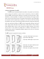
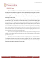
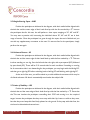
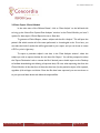
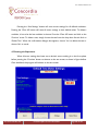
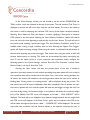
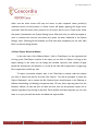
1
PC-POD-FA-002-v01
PERFORM Operating Document
NeuroCom® SMART EquiTest®
Computerized Dynamic Posturography (CDP)
PC-POD-FA-002-v01
Revision History
Version
01
Reason for Revision
Date
New POD
Jan/15/2015
Summary
The content of this PERFORM Operating Document (POD) provides guidelines for:
- Operation of the NeuroCom SMART EquiTest® device
- Safety measures to consider with patients
- Use of the Clinical and Research modules
- Data export
PC-POD-FA-002-v01
Printed copies are not controlled.
Page 1 of 22
PC-POD-FA-002-v01
Table of Contents
SUMMARY----------------------------------------------------------------------------------- 1
1. DEFINITION OF TERMS ------------------------------------------------------------- 3
2. INTRODUCTION --------------------------------------------------------------------- 4
2.1 GENERAL MAINTENANCE -------------------------------------------------------------------------------------- 5
2.2 HARNESS PLACEMENT ------------------------------------------------------------------------------------------ 5
3. CLINICAL MODULE: COMPUTERIZED DYNAMIC POSTUROGRAPHY
(CDP) ----------------------------------------------------------------------------------------- 6
3.1OVERVIEW AND BASIC CLINICAL MODULE SETUP ----------------------------------------------------------- 6
3.2 SENSORY ORGANIZATION TEST (SOT) ---------------------------------------------------------------------- 9
3.3 MOTOR CONTROL TEST (MCT)---------------------------------------------------------------------------- 11
3.4 ADAPTATION TEST (ADT) ---------------------------------------------------------------------------------- 12
3.5 WEIGHT BEARING SQUAT – WBS -------------------------------------------------------------------------- 13
3.6 UNILATERAL STANCE – US ---------------------------------------------------------------------------------- 13
3.7 LIMITS OF STABILITY – LOS ---------------------------------------------------------------------------------- 13
3.8 DATA EXPORT: CLINICAL MODULE ------------------------------------------------------------------------ 14
4. RESEARCH MODULE ----------------------------------------------------------------- 15
4.1 OPTIONS ------------------------------------------------------------------------------------------------------4.2 MOTOR SETTINGS -------------------------------------------------------------------------------------------4.3 RUNNING THE EXPERIMENT --------------------------------------------------------------------------------4.4 DATA EXPORT: RESEARCH MODULE -----------------------------------------------------------------------
APPENDIX I
PC-POD-FA-002-v01
Printed copies are not controlled.
Page 2 of 22
16
17
20
22
PC-POD-FA-002-v01
1. Definition of Terms
ADT
Adaptation Test
CDP
Computerized Dynamic Posturography
COP
Center of Pressure
LOS
Limits of Stability
MCT
Motor Control Test
POD
PERFORM Operating Document
RWS
Rhythmic Weight Shift
SOT
Sensory Organization Test
SOP
Standard Operating Procedure
Users
Any trained person that is using instruments/equipment at the
PERFORM Centre
US
Unilateral Stance
WBS
Weight Bearing Squat
PC-POD-FA-002-v01
Printed copies are not controlled.
Page 3 of 22
PC-POD-FA-002-v01
2. Introduction
The SMART EquiTest® provides objective assessment of balance control and postural
stability under dynamic test conditions to reflect the challenges of daily life. The SMART
EquiTest includes the full battery of tests that comprise Computerized Dynamic Posturography
(CDP). The System provides assessment and retraining capabilities with visual biofeedback on
either a stable or unstable support surface and in a stable or dynamic visual environment.
PC-POD-FA-002-v01
Printed copies are not controlled.
Page 4 of 22
PC-POD-FA-002-v01
2.1 General Maintenance
Operational safety and efficacy of your NeuroCom® Balance Manager® system depends not only on
clinical expertise, but also on the care and maintenance of the device. Regular cleaning, inspection, and
maintenance will assure continued performance and safety of the system.
Inspect the operation of the force plate rotate and translate functions, as well as the function of the
visual surround for smooth, quiet operation.
Verify that all computer peripherals are plugged into the NeuroCom® supplied plug strip or accessory
plugs on the back of the dynamic system base. The plug strip must also be connected to one of the
accessory plugs on the back of the dynamic system base. Qualified service personnel should check the
system for loose fasteners, brackets, plugs, and panels. Repairs should be made if problems are detected.
Refer to the service manual for additional service related information.
2.2 Harness placement
Participant safety depends on the performance of the safety harness. Inspect the harness for frayed
material, straps, and damaged buckles. If replacement is required, contact NeuroCom® Technical
Support.
Participants who are running through any kind of testing, whether there are large movements
anticipated or no movement at all, must wear a safety harness while on the NeuroCom EquiTest device.
The sizes are S, M and L, and the guidelines for each size are for persons between 4’10” – 5’4”, 5’4” –
6’0” and 6’0”+, respectively. All harnesses are tested to 200kg (441 lbs).
- Have the patient put on the harness as if it were asmall backpack.
- Fasten the plastic buckle in front at the patient’s waist.
- Pull the leg straps forward between the patient’s legs and fasten the plastic buckles.
- Adjust the fit of all the straps until the
harness feels snug, but comfortable.
- Follow steps 1 through 4 to ensure the
buckles of the harness are properly fastened
and ‘double-back’.
- If the Harness is not properly fastened, the
risk of the participant injuring themselves
during a fall greatly increases. Ensure you
are comfortable putting on and taking off
harnesses on a multitude of body types
before beginning your testing.
PC-POD-FA-002-v01
Printed copies are not controlled.
Page 5 of 22
PC-POD-FA-002-v01
3. Clinical Module: Computerized Dynamic Posturography (CDP)
3.1Overview and Basic Clinical Module Setup
The strength of the EquiTest is that it allows clinicians an objective and systematic way
of manipulating somatosensory and visual information. The precise test data accurately
identifies and differentiates underlying sensory and motor impairments, and enhances the ability
to diagnose and treat problems of imbalance and postural instability, especially for those
patients who previously proved difficult to diagnose.
The SMART EquiTest includes the following standardized assessment protocols:
Sensory Organization Test (SOT)
Motor Control Test (MCT)
Adaptation Test (ADT)
Limits of Stability (LOS)
Rhythmic Weight Shift (RWS)
Weight Bearing Squat (WBS)
Unilateral Stance (US)
SOT, MCT and ADT comprise the core battery of tests recognized as Computerized
Dynamic Posturography (CDP), considered the highest standard available for diagnosing the
functional impairments underlying balance disorders.
CDP is a unique assessment tool used to objectively quantify and differentiate among
the wide variety of possible sensory, motor, and central adaptive impairments to balance
control. As such, CDP is complementary to clinical tests designed to localize and categorize
pathological mechanisms of balance disorders. CDP can identify and differentiate the functional
impairments associated with the pathological processes. By itself, CDP cannot diagnose
pathology or site-of-lesion; it simply provides a score of which system demonstrates a deficit.
PC-POD-FA-002-v01
Printed copies are not controlled.
Page 6 of 22
PC-POD-FA-002-v01
Because of the complex interactions among sensory, motor, and central adapting
processes, CDP requires separate protocols to adequately differentiate among impairments.
To quantify the deficiency of adaptive mechanisms to select appropriate sensory inputs and
movement response patterns, CDP exposes the patient to a variety of controlled visual and
support surface conditions.
The contribution of CDP information to positive treatment outcomes has been
demonstrated in numerous controlled studies. A thorough overview of CDP methodology and
clinical applications can be found in "Practical Management of the Dizzy Patient," edited by Joel
A. Goebel (Lippincott Williams & Wilkins Publishers 2000).
To turn on the EquiTest, flip the power switch on the bottom right hand side of the
device. You will know there is power to the machine when the lights in the EquiTest will turn
on. Then, turn the operating computer on. When the screen turns on, it will display a ‘System
Initialization’ screen. Ensure there is nothing on the force plates, and that nothing is obstructing the
path of the visual surround of the EquiTest. Press ‘Continue’ on the initialization screen to zero
the force plates and visual surround.
To begin testing, click on ‘Clinical Module’ in the main screen. From there, you will be in
the ‘File Cabinet’, where you have the option of searching a previous subject or creating a new
patient. If this is a new subject, click ‘New Patient File’ to open the subject information window.
If it is a previously entered subject, simply highlight the desired subject and click ‘Continue’. The
‘Quick Find’ function may also be used to quickly search for the subject. Ensure the subject
information is correctly filled; height and age are important for calculating variables and
normative comparisons. Click on ‘Assessment’ to bring up the different tests available on the
EquiTest. Click on Sensory Organization Test (SOT).
Place the harness of appropriate size on the subject as is explained in section 2.2, and
instruct them it is a precautionary measure in case of a loss of balance which is unlikely. Also
instruct them that the amount of movement on the device is minimal but that it may be
disorienting. The sizes are S, M and L for people of various sizes. All of them are rated for the
PC-POD-FA-002-v01
Printed copies are not controlled.
Page 7 of 22
PC-POD-FA-002-v01
same weight of 200kg (441lbs). The carabineers must be fastened to the harness, but must still
allow for natural movement and sway. A good way of ensuring the individual still has normal
mobility is by loosening the top straps until the carbineers lay flat on the subject’s shoulders.
Ask them to move side to side and front to back, asking them if they feel the straps pulling. If
they do, loosen them slightly and repeat the same test. Place the person’s feet as shown in the
figure below. First, line-up the subject’s ankles with the thick horizontal line that passes through
the axis of rotation of the force plates. This can easily be achieve by using your hand; line-up
your thumb with the subjects medial malleolus and your fingers with the horizontal line. Then,
place the outside of the person’s heels on the vertical line marked by a ‘T’. Once the subject’s
ankles are lined up and their heels are in place, they may splay their feet in a more comfortable
position, ensuring their heels remain in place. See below.
Foot Placement. Note the alignment of the
ankle and the force-plate axis of rotation, as
well as the heel and the line labeled ‘T’.
PC-POD-FA-002-v01
Notice that the ankle and heel are still
properly aligned, but the feet are in slight
external rotation for patient ergonomics.
Printed copies are not controlled.
Page 8 of 22
PC-POD-FA-002-v01
3.2 Sensory Organization Test (SOT)
The SOT protocol objectively identifies abnormalities in the patient's use of the three
sensory systems that contribute to postural control: somatosensory, visual and vestibular.
During the SOT, useful information delivered to the patient's eyes, feet and joints is either
eliminated or rendered unreliable to the patient by "sway referencing" of the support surface
and/or visual surround. What this means is the patient’s anterior/posterior sway directly affects
the movement of the force plates they are standing on or the visual surround. By controlling
the usefulness of the sensory (visual and proprioceptive) information through sway referencing
and/or eyes open/closed conditions, the SOT protocol systematically eliminates useful visual
and/or support surface information and creates sensory conflict situations. These conditions
isolate vestibular balance control, as well as pressure the adaptive responses of the central
nervous system. In short, patients may display either an inability to make effective use of
individual sensory systems or inappropriate adaptive responses, due to the use of inaccurate
environmental information.
The SOT protocol is comprised of six sensory conditions:
1. Eyes-open, stable support and surround
2. Eyes-closed, stable support
3. Eyes-open, stable support, sway surround
4. Eyes-open, sway support, stable surround
5. Eyes-closed, sway support
6. Eyes-open, sway support, sway surround
PC-POD-FA-002-v01
Printed copies are not controlled.
Page 9 of 22
PC-POD-FA-002-v01
Once in the SOT, ensure that Condition 1 Trial 1 is selected, and instruct the individual
to keep their eyes opened and to stand still. Tell the individual that the trials last 20 seconds,
and that if at any time they would like to stop, to simply raise their hand. Ensure the screen
inside the EquiTest is turned off; otherwise the subject will receive feedback on the position of
their center of mass (CoM).
Ask the participant if they are ready to start. Once they are ready, alert them that the
trial will start on ‘Go’. Click ‘Start’, the screen will prompt you to instruct the subject. Begin
the countdown: ‘3, 2, 1 and go’ and then press any key or right-click the mouse to begin. When
the trial has finished, a chime will become audible. Instruct the subject the trial is over and that
trial 2 will begin shortly. Repeat the same as before. If at any point during a trial, the participant
takes a step to regain their balance, grabs the walls, asks to stop or falls, mark the trial as a fall.
At the end of the session, you will be asked to write a comment regarding the session. This is
where the details of a missed trial must be elaborated.
Go on to the next condition and follow the same steps as before, describing each new
condition to the subject. EquiTest will provide you with a brief description of the condition
type before every trial.
Once all the trials and conditions have been completed, click on ‘Assessment Menu’.
The software will prompt you and ask if you want to continue. Click ‘Yes’. It will then prompt
you to add a comment, do so if necessary then click ‘OK’. The subject data will automatically be
saved under the subject’s name with the current date.
PC-POD-FA-002-v01
Printed copies are not controlled.
Page 10 of 22
PC-POD-FA-002-v01
3.3 Motor Control Test (MCT)
The MCT assesses the patient's ability to quickly and automatically recover from
unexpected external provocations. Sequences of small, medium or large (scaled to the patient's
height) platform translations in forward and backward directions elicit automatic postural
responses. Measurements include onset timing, strength and lateral symmetry of responses.
Follow the instruction to position the participant’s feet
correctly. Once in the MCT, the first ‘practice trial’ of
the MCT will be selected by default. Instruct the
individual to keep their eyes opened and to stand still.
Tell the participant that the platforms will shift
backward at a slow speed, and to try and remain as
well balanced as possible.
Forward and backward translations
For every condition (small, medium and large perturbations) there will be a total of 3
trials. If the participant falls during the test, this will count toward there score, but if they fall
twice the test will be terminated. After the backward conditions are completed, the test will
continue in the same fashion (3 trials per condition) in the forward direction.
As before, when the test is complete, you will be prompted to provide any additional
comments you think are clinically relevant for the participant. Subject data is automatically
saved under the subject’s name with the current date.
PC-POD-FA-002-v01
Printed copies are not controlled.
Page 11 of 22
PC-POD-FA-002-v01
3.4 Adaptation Test (ADT)
The ADT assesses the patient's ability to modify motor reactions and minimize sway
when the support moves unpredictably in the toes-up or toes-down direction. For each
platform rotation, a sway energy score quantifies the magnitude of the force response required
to overcome induced postural instability. This adaptive test simulates daily life conditions such
as irregular support surfaces.
Follow the instruction to position the participant’s feet
correctly. Once in the ADT, the first ‘practice trial’ of
the ADT will be selected by default. Instruct the
individual to keep their eyes opened and to stand still.
Tell the participant that the platforms will rotate
around their ankles in such a way to make their toes
point upward.
Forward and backward translations
There will be 5 trials of an 8 degree rotation about the ankle joint for both the ‘Toes
Up’ condition and the ‘Toes Down’ condition. The test does not get progressively more
difficult (i.e. it is the same perturbation every trial). After the first 5 trials, instruct the
participant that the platform will now move in the opposite direction, rotating downward.
As before, when the test is complete, you will be prompted to provide any additional
comments you think are clinically relevant for the participant. Subject data is automatically
saved under the subject’s name with the current date.
PC-POD-FA-002-v01
Printed copies are not controlled.
Page 12 of 22
PC-POD-FA-002-v01
3.5 Weight Bearing Squat – WBS
Position the participant as indicated in the diagram, with their medial ankles aligned with
the dark bar and the outer edge of their heels lined up with the line marked by a ‘T’. Instruct
the participant that for this test, the will perform a slow squat, stopping at 30°, 60° and 90°.
You may want a practice trial, instructing the individual where 30°, 60° and 90° are in their
range of motion. Once the participant has gone through the squat, the test is finished and you
can add any supplementary comments to the test. If it was too fast for the participant, simply
perform the test again.
3.6 Unilateral Stance – US
Position the participant as indicated in the diagram, with their medial ankles aligned with
the dark bar and the outer edge of their heels lined up with the line marked by a ‘T’. This test
involves standing on one leg, first the left and then the right, with eyes-opened (EO) followed
by eyes-closed (EC). There will be 3 10 second trials for each condition. If standing on one leg
for 6 consecutive trials is too demanding for the participant, you may begin with the left leg EO,
and then go to right leg EO before switching back to left leg EC and finishing with right leg EC.
At the end of the test, you will be asked to provide additional comments which may be
of clinical relevance. All data is automatically saved under the subject’s file.
3.7 Limits of Stability – LOS
Position the participant as indicated in the diagram, with their medial ankles aligned with
the dark bar and the outer edge of their heels lined up with the line marked by a ‘T’. Esure that
the This test involves the participant controlling their COP and moving it to the required
target. Instruct the participant that they must sway with their hip, knees or ankle as they want,
but that they must keep their feet firmly planted on the ground. If they step with their feet, the
trial must be discarded and started over.
PC-POD-FA-002-v01
Printed copies are not controlled.
Page 13 of 22
PC-POD-FA-002-v01
3.8 Data Export: Clinical Module
In the main menu of the ‘Balance Master’, click on ‘Data Analysis’ on the left-hand side
to bring up the ‘NeuroCom System Data Analyzer’ window. In the Clinical Module, you have 2
options for data export: Clinical Report format or Raw data.
To generate a Clinical Report, select a subject and the click ‘Analysis’. This will open the
patient’s file which contains all of the tests performed, in chronological order. From here, you
can select the kind of results that will be generated in your report, and you can chose to create
a PDF or print it right away.
To export a particular subject’s raw data, in the ‘Data Analyzer window’, select the
subject you wish to export the data for and then click ‘Export’. You will be prompted to select
the ‘Export Destination’ and to rename the file if desired (users should export to the Desktop
to facilitate downloading and deleting of exported data). Of note, when exporting data from the
Clinical Module, all data that from all dates that have been for that particular subject will be exported,
regardless of the trial type or trial date. Once the files have been exported, you can save them on
to your personal data device and delete the exported files.
PC-POD-FA-002-v01
Printed copies are not controlled.
Page 14 of 22
PC-POD-FA-002-v01
4. Research Module
Clicking ‘Research Module’ will bring up the ‘File Cabinet’ window, where you will be
able to either enter a new subject into the system, or chose a previous subject file to continue
testing with.
When you click on ‘New Subject File’, a window allowing you to enter the subject’s
information will come up. Fill out all the necessary information pertinent to your study. Once
finished, click next to enter the Main Menu, where you will be able to setup your experiment,
or export previously collected data.
Clicking ‘Setup’ initializes the zeroing of the force plates; therefore ensure nothing is on
them. After the force plates are zeroed, the ‘Motor Settings’ menu will appear. To setup your
experiments, click on ‘New Test’. Here again, enter a descriptive and specific experiment name,
since this device is used by other users as well.
The experimental tests are divided into ‘Conditions’ comprised of multiple ‘Trials’. Begin
by entering a descriptive name to ‘Condition’. The options are shown in the figure below.
PC-POD-FA-002-v01
Printed copies are not controlled.
Page 15 of 22
PC-POD-FA-002-v01
4.1 Options
Trial Duration: This allows you to vary the length of time of all the trials in this condition.
Trial durations can be set to any value between 1 and 600 seconds. The default is 1second.
Number of Trials: Number of trials with the same settings that will be a part of this
‘Condition’.
Output Signal Pulse: Selecting this option provides a trigger pulse to trigger an external
device. The transition of the sync pulse can be set as initial low, active high or initial high, active
low. A delay in seconds relative to the onset of data acquisition can also be specified. For
example, if the delay is zero, the state of the sync output will change at the moment the trial
starts.
Show Cursor: This will toggle the subject’s COP on/off, which may be useful for the tester. If
the feedback LCD is on in the device, this will provide the subject with feedback on where
their COP is. NOTE: This setting does not apply to pre-testing as the cursor is always shown
prior to trial initiation.
Show Trace: This will toggle the trace of the subject’s COP. Much like the Cursor, this may
be useful for both the tester and subject. NOTE: This setting does not apply to pre-testing.
Test Trigger End Test: Selecting this option will terminate the trial by a state change of the
initiating trigger For example, if Weight test trigger is selected, the trial will end when the
weight on the force plate falls below the specified threshold. If this option is not selected, the
end of a trial is determined by the value entered for the trial duration.
Accessory Channels: Number of accessory channels (0-8) enabled for data collection from
external devices.
Collect Sync Line Status Data: Selecting this option will result in sync line status data
collection.
PC-POD-FA-002-v01
Printed copies are not controlled.
Page 16 of 22
PC-POD-FA-002-v01
Test Triggers: The following options allow the operator to choose the type of trigger that
initiates a trial:
• Mouse click: a trial is initiated during the pretest when the operator clicks the mouse
button.
• Weight: a trial is initiated during the pretest when the weight detected on the force plate
equals or exceeds the specified weight trigger threshold. The operator can specify the
weight threshold once the weight trigger is selected. Once a trial is initiated by the weight
trigger, it will be terminated if the Test Trigger Ends Test option is set and the detected
weight falls below the specified weight threshold.
• Sync pulse: a trial is initiated when a signal state change is detected on the Master In line of
the I/O Switch box. If the Test Trigger Ends Test option is set, a signal state change on
the Master In line will terminate the trial.
In all cases, the occurrence of the selected trigger event will advance the trial from the pretest
phase to the test phase at which time all motor parameters will be executed and data
acquisition will begin.
Randomize Conditions: Selecting this option will randomize the sequence of predefined
conditions. Note: All trial settings will remain unchanged.
4.2 Motor Settings
The Motor Settings menu has a tree like structure, with the ROTATE, TRANSLATE and
VISUAL motors being the roots. This structure allows the operator to select and set the
parameters for each motor to run independently.
Selecting any one of the three motors will display the supported test modes: SWAY,
RAMP, WAVEFORM and FIXED. The default mode for each motor is FIXED so that the motor
will remain stationary during the test. Hence, there are no settings associated with the FIXED
mode. The SWAY, RAMP, and WAVEFORM modes are described in detail below.
PC-POD-FA-002-v01
Printed copies are not controlled.
Page 17 of 22
PC-POD-FA-002-v01
Sway: This option sets the selected motor to the sway-referenced mode such that its
movement will follow the subject’s COP. When a positive Sway Gain is specified, the
movement will be in the same direction as the subject’s COP. When a negative Sway Gain is
specified, the movement will be in the opposite direction as the subject’s COG. For example, if
the ROTATE motor Sway Gain is 1.0, the force plate will tilt toes-down one degree when
subject’s COP moves forward one degree. If the TRANSLATE Sway Gain is 1.0, when subject’s
COP moves one inch, the platform will move one inch in the same direction as the COP.
Ramp: Selecting the Ramp mode will display all supported settings: Start Position, End Position,
Ramp Time and Ramp Delay. The range over which each of these parameters may be set varies
as a function of the motor selected as shown in the following table:
Motor
Rotate
Translate
Visual
Range and Direction
-10° Toes up
+10° Toes down
-6.35 cm Backward
+6.35 cm Forward
-10° Toward Subject
+10° Away from Subject
Maximum Velocity
50 °/s
20 cm/s
15 °/sec
Position Error
+/- 0.01°
+/- 0.01cm
+/- 0.01°
The Ramp Time determines the amount of time for the selected motor to achieve the
maximum excursion as set by the absolute difference between the Start and End Positions. This
value is selectable from 0 sec to 65 seconds. The minimum Ramp Time for a given excursion is
limited by maximum performance capabilities of a given motor.
The Ramp Delay determines the time delay between the onset of data collection and the
active movements of the selected motor(s). This variable is selectable from 0 to the maximum
value of the Duration - Ramp Time in seconds, i.e. the sum of Ramp Time and Ramp Delay
cannot exceed the total Trial Duration.
PC-POD-FA-002-v01
Printed copies are not controlled.
Page 18 of 22
PC-POD-FA-002-v01
Selecting the Sync Pulse Trigger option will initiate a preset motor profile by detecting a
signal state change on the corresponding motor input line.
Waveform: If a given waveform has been associated with the displayed trial for a given
condition, it will be displayed on the screen along with the associated wave function.
Otherwise, that portion of the screen will be blank. Selecting the Waveform Setup button will
advance to the waveform setup screen, which will allow the operator to specify a wave function
to model the motor movement.
Each waveform setup screen applies to the selected motor only. To graph a function,
enter the corresponding math function in the text box labeled “F(t) =” and select the Graph
Function button. The function will be drawn in green. This graph then represents a movement
model for the selected motor. The accepted ranges of movement functions are most
recognized mathematical functions. Different functions can also be specified for different time
segments within a trial. Only functions of time (t) will be correctly calculated. Any other
variables will result in a calculation of zero for all instances of that variable. However, the
predefined constant “PI” can be used with any function, for example: Cos(2* PI *0.5*t). If a
syntax error is detected, a descriptive error message will be displayed for guidance. The graph
conforms to the amplitude specification for each motor as shown in the previous table. If the
specified function exceeds the operational limit of the selected motor, the motor movement
amplitude will saturate, and the position will remain at this maximum value throughout the time
the function value remains above the functional limit of the motor.
To set the entire function to the operational limits of specified motor, select the FullScale Function button. The full-scale function will be drawn in blue and the graph legend will
show the scaling factor. This auto scaling is based on the value of the function that is furthest
away from the operational limits of the motor. This point is used to find the base scaling-factor
that is applied to the complete function. This feature allows for all functions to be scaled down
or up in order to take advantage of the maximum performance of the system.
PC-POD-FA-002-v01
Printed copies are not controlled.
Page 19 of 22
PC-POD-FA-002-v01
Pressing the ‘Save Settings’ button will save current settings for all defined conditions.
Pressing the ‘Clear All’ button will reset all motor settings to their default values. To delete a
condition, it has to be the last condition in the test. Press the ‘Clear All’ button and click on the
‘Previous’ arrow. To delete a test, simply choose the test from the drop down list and click on
‘Delete Test’. When the confirmation dialogue box appears, choose ‘Yes’ to delete the test or
choose ‘No’ to cancel.
4.3 Running the Experiment
When all motor settings have been set as desired, ensure nothing is on the force plates
before pressing the ‘Continue’ button to advance to the test screen, as shown in figure bellow.
Once initialized, the program will advance to the test screen.
PC-POD-FA-002-v01
Printed copies are not controlled.
Page 20 of 22
PC-POD-FA-002-v01
In the ‘Motor Settings’ window, you will be able to see the current CONDITION and
TRIAL number, which are indicated at the top of the screen. The trial duration (Trial Timer) is
displayed in seconds and will count down until the trial time elapses. The area in the middle of
the screen is used for displaying the real-time COP cursor (if that option has been selected).
Selecting ‘Show Reference Point’ will display a crosshair signifying a fixed point of centered
COP relative to the force plate. Selecting the ‘Auto-Advance Conditions’ option will advance
from one trial to the next bypassing a required click on the ‘Start’ button. The trial will wait in
the pretest mode, awaiting a preset test trigger. The ‘Auto-Advance Conditions’ option is not
available when running a single condition with one trial. Selecting the ‘Bypass Test Triggers’
option will display a warning message. When using this option, a concluded trial will advance to
the next trial, bypassing any preset test trigger. Take caution when using this mode, as trials will
advance without pause or warning. This mode can be terminated by simply interrupting any
trial. To use this option (which is a near continuous data acquisition mode), configure the
following options in the ‘System Settings’: uncheck ‘Show Post Test Comment’, uncheck ‘Show
Review Graphs’, and check’ Auto-Save Trials’.
Pressing the ‘Start’ button will start the pretest phase of the trial. If waveform
operations have been selected, a brief moment preceding the pretest phase will occur at which
time waveform data will be transferred to the system. Also, if the motor starting positions are
off center, the motors will initialize to the starting position before the test can be started. A
blinking label “Moving motors to starting position” will be displayed during this process. The
test cannot start until all motor initializations have been completed. Once in pretest, the realtime cursor updates will occur and the system will await the test trigger to begin the trial. If at
any time during testing, the detected weight on the platform falls below the minimum weight
limit (10 lbs default), the COP cursor will disappear and a label “…LOW WEIGHT” will be
displayed. This label will in turn disappear when detected weight exceeds the low weight limit
and COP cursor will reappear. If the Show Cursor option was not selected, the COP cursor
will be hidden throughout the trial and a label “…CURSOR OFF” will be displayed. The test will
stop under two conditions: the trial duration elapses or the operator interrupts the test. In
PC-POD-FA-002-v01
Printed copies are not controlled.
Page 21 of 22
PC-POD-FA-002-v01
either case the active motors will stop and return to their respective center position(s)
otherwise known as level position. A review screen will appear graphing the target motor
movement with the actual motor positions for all motors that are not in Fixed mode, unless
this option is deselected in the ‘System Settings’ menu. After each trial, you will be prompted to
write a comment and save the trial (unless this option has been deselected in the System
Settings’ menu. Following all the Conditions and Trials have been completed, you can click ‘Main
Menu’ to exit the testing window.
4.4 Data Export: Research Module
In the main menu of the ‘Balance Master’, click on ‘Data Export’ on the right-hand side
to bring up the ‘Data Export’ window. In this menu, you can click on ‘Options’ to bring up the
export settings. In this menu you can change the variables reported, units, number of digits
passed the decimal point and whether or not the all the trials will be exported in a single large
file or exported as one file per trial.
To export a particular subject’s data, in the ‘Data Export’ window, select the subject
you wish to export the data for and then click ‘Export’. You will be prompted to select the
‘Export Destination’ and to rename the file if desired (users should export to the Desktop to
facilitate downloading and deleting of exported data). Of note, when exporting data from the
Research Module, all data that from all dates that have been for that particular subject will be
exported, regardless of the trial type or trial date. Once the files have been exported, you can save
them on to your personal data device and delete the exported files.
PC-POD-FA-002-v01
Printed copies are not controlled.
Page 22 of 22
PC-POD-FA-002-v01
APPENDIX I
POD Training Record Form
PC-POD-FA-002-v01
Printed copies are not controlled.
APPENDIX I
PC-POD-FA-002-v01
POD Title
NeuroCom® SMART EquiTest®
Computerized Dynamic Posturography (CDP)
SOP Code
Ownership
Document type
Area
SOP Number
Version
PC
POD
FA
002
01
Training Record
Full Name
Institution
Contact
(email or phone number)
Signature
Sign here (Trainee)
Date
Sign Here (Functional Assessment Coordinator)
Date