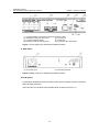
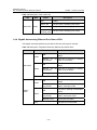
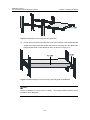
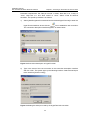
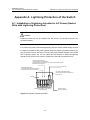
1
H3C S5100-SI/EI Series Ethernet Switches
Installation Manual
Hangzhou H3C Technologies Co., Ltd.
http://www.h3c.com
Manual Version: 20080123-C-1.05
Copyright © 2007-2008, Hangzhou H3C Technologies Co., Ltd. and its licensors
All Rights Reserved
No part of this manual may be reproduced or transmitted in any form or by any means
without prior written consent of Hangzhou H3C Technologies Co., Ltd.
Trademarks
H3C,
, Aolynk,
, H3Care,
, TOP G,
, IRF, NetPilot,
Neocean, NeoVTL, SecPro, SecPoint, SecEngine, SecPath, Comware, Secware,
Storware, NQA, VVG, V2G, VnG, PSPT, XGbus, N-Bus, TiGem, InnoVision and
HUASAN are trademarks of Hangzhou H3C Technologies Co., Ltd.
All other trademarks that may be mentioned in this manual are the property of their
respective owners.
Notice
The information in this document is subject to change without notice. Every effort has
been made in the preparation of this document to ensure accuracy of the contents, but
all statements, information, and recommendations in this document do not constitute
the warranty of any kind, express or implied.
To obtain the latest information, please access:
http://www. h3c.com
Technical Support
[email protected]
http://www. h3c.com
About This Manual
Related Documentation
In addition to this manual, each H3C S5100-SI/EI Series Ethernet Switches
documentation set includes the following:
Manual
Description
H3C S5100-SI/EI Series Ethernet
Switches Operation Manual
It is used for assisting the users in data
configurations and typical applications.
H3C S5100-SI/EI Series Ethernet
Switches Command Manual
It is used for assisting the users in using
various commands.
Organization
H3C S5100-SI/EI Series Ethernet Switches
follows:
Chapter
Installation Manual is organized as
Contents
1 Product Overview
Introduces the characteristics and technical
specifications of S5100-SI/EI Series Ethernet
Switches.
2 Preparing for Installation
Introduces the installation preparation and precaution
of S5100-SI/EI Series Ethernet Switches.
3 Installing the Switch
Introduces the procedures to install an S5100-SI/EI
Series Ethernet Switch, including the setup of the
mainframe, cards and cables.
4 Powering on the Switch
for the First Time
Introduces the booting process of an S5100-SI/EI
Series Ethernet Switch, including the power-on
booting of the switch and the system initialization.
5 Boot ROM and Host
Software Loading
Introduces how to load BootROM and host software
for an S5100-SI/EI Series Ethernet Switch.
6 Maintenance and
Troubleshooting
Introduces the problems that might occur during the
installation and the booting of an S5100-SI/EI Series
Ethernet Switch and the related solution.
7 Appendix A
Introduces lightning protection of S5100-SI/EI Series
Ethernet Switches.
Conventions
The manual uses the following conventions:
I. GUI conventions
Convention
Description
<>
Button names are inside angle brackets. For example, click
<OK>.
[]
Window names, menu items, data table and field names
are inside square brackets. For example, pop up the [New
User] window.
/
Multi-level menus are separated by forward slashes. For
example, [File/Create/Folder].
II. Symbols
Convention
Description
Warning
Means reader be extremely careful. Improper operation
may cause bodily injury.
Caution
Means reader be careful. Improper operation may cause
data loss or damage to equipment.
Note
Means a complementary description.
Environmental Protection
This product has been designed to comply with the requirements on environmental
protection. For the proper storage, use and disposal of this product, national laws and
regulations must be observed.
Installation Manual
H3C S5100-SI/EI Series Ethernet Switches
Table of Contents
Table of Contents
Chapter 1 Product Overview ........................................................................................................ 1-1
1.1 Preface............................................................................................................................... 1-1
1.2 S5100-SI Series Ethernet Switches................................................................................... 1-2
1.2.1 S5100-8P-SI Ethernet Switch ................................................................................. 1-2
1.2.2 S5100-16P-SI Ethernet Switch ............................................................................... 1-4
1.2.3 S5100-24P-SI Ethernet Switch ............................................................................... 1-6
1.2.4 S5100-48P-SI Ethernet Switch ............................................................................... 1-7
1.3 S5100-EI Series Ethernet Switches................................................................................... 1-8
1.3.1 S5100-8P-EI Ethernet Switch ................................................................................. 1-8
1.3.2 S5100-16P-EI Ethernet Switch ............................................................................... 1-9
1.3.3 S5100-24P-EI Ethernet Switch ............................................................................. 1-10
1.3.4 S5100-48P-EI Ethernet Switch ............................................................................. 1-12
1.3.5 S5100-26C-EI Ethernet Switch ............................................................................. 1-13
1.3.6 S5100-50C-EI Ethernet Switch ............................................................................. 1-15
1.3.7 S5100-8P-PWR-EI Ethernet Switch...................................................................... 1-16
1.3.8 S5100-16P-PWR-EI Ethernet Switch.................................................................... 1-18
1.3.9 S5100-26C-PWR-EI Ethernet Switch.................................................................... 1-20
1.3.10 S5100-50C-PWR-EI Ethernet Switch.................................................................. 1-21
1.4 LEDs ................................................................................................................................ 1-23
1.4.1 Power LED (PWR) ................................................................................................ 1-23
1.4.2 DC Power Supply LED (RPS) ............................................................................... 1-24
1.4.3 Mode LED ............................................................................................................. 1-24
1.4.4 Gigabit Autosensing Ethernet Port Status LEDs................................................... 1-25
1.4.5 Gigabit SFP Port Status LED ................................................................................ 1-26
1.4.6 Module LED........................................................................................................... 1-27
1.4.7 7-Segment Digitron Display .................................................................................. 1-28
1.5 System Features of the S5100 Series ............................................................................. 1-30
1.5.1 System Features of the S5100-SI Series.............................................................. 1-30
1.5.2 System Features of the S5100-EI Series.............................................................. 1-31
1.6 Ordering SFP/XFP/XENPAK Interface Modules ............................................................. 1-34
1.7 Ordering 10 G Stack Interface Modules .......................................................................... 1-35
1.8 Ordering Stack Cables..................................................................................................... 1-36
1.9 Ordering DC Power cords................................................................................................ 1-36
Chapter 2 Preparing for Installation ............................................................................................ 2-1
2.1 Safety Precautions............................................................................................................. 2-1
2.2 Installation Site................................................................................................................... 2-1
2.2.1 Temperature/Humidity............................................................................................. 2-1
i
Installation Manual
H3C S5100-SI/EI Series Ethernet Switches
Table of Contents
2.2.2 Cleanness ............................................................................................................... 2-2
2.2.3 Electromagnetic Susceptibility ................................................................................ 2-2
2.2.4 Safety in Use of Laser............................................................................................. 2-3
2.3 Installation Tools ................................................................................................................ 2-3
Chapter 3 Installing the Switch .................................................................................................... 3-1
3.1 Rack-Mounting the Switch ................................................................................................. 3-1
3.1.1 Introduction to Mounting Ear ................................................................................... 3-2
3.1.2 Introduction to Guide Rail........................................................................................ 3-4
3.1.3 Using Front Mounting Ears to Install a Switch ........................................................ 3-4
3.1.4 Use Front Mounting Ears and a Tray...................................................................... 3-5
3.1.5 Use Front and Rear Mounting Ears ........................................................................ 3-6
3.1.6 Use Front Mounting Ears and Guide Rails ............................................................. 3-9
3.2 Desk Mounting ................................................................................................................. 3-12
3.3 Wall Mounting .................................................................................................................. 3-12
3.4 Magnet Mounting ............................................................................................................. 3-13
3.5 Connecting Power Cord and Grounding Wire ................................................................. 3-16
3.5.1 Connecting AC Power Cord .................................................................................. 3-16
3.5.2 Connecting DC Power Cord.................................................................................. 3-17
3.5.3 Connecting Grounding Wire.................................................................................. 3-19
3.6 Connecting Console Cable .............................................................................................. 3-21
3.6.1 Console Cable....................................................................................................... 3-21
3.6.2 Connecting Console Cable ................................................................................... 3-22
3.7 Installing and Removing Optional Interface Modules ...................................................... 3-23
3.7.1 XFP Interface Module ........................................................................................... 3-23
3.7.2 Stack Module......................................................................................................... 3-25
3.7.3 XENPAK Optical Module....................................................................................... 3-26
3.8 Installing and Removing Dedicated Stack Cables........................................................... 3-28
3.8.1 Introduction............................................................................................................ 3-28
3.8.2 Installation ............................................................................................................. 3-28
3.8.3 Removal ................................................................................................................ 3-28
3.9 Verifying the Installation................................................................................................... 3-29
Chapter 4 Powering on the Switch for the First Time................................................................ 4-1
4.1 Set up the Configuration Environment............................................................................... 4-1
4.2 Connecting the Console Cable .......................................................................................... 4-1
4.3 Setting Terminal Parameters ............................................................................................. 4-1
4.4 Booting the Switch ............................................................................................................. 4-4
4.4.1 Checking before Powering on the Switch ............................................................... 4-4
4.4.2 Powering on the Switch........................................................................................... 4-4
4.4.3 Changing the Startup Mode .................................................................................... 4-6
Chapter 5 Boot ROM and Host Software Loading ..................................................................... 5-1
5.1 Introduction to Loading Modes .......................................................................................... 5-1
ii
Installation Manual
H3C S5100-SI/EI Series Ethernet Switches
Table of Contents
5.2 Local Software Loading ..................................................................................................... 5-1
5.2.1 Boot Menu ............................................................................................................... 5-2
5.2.2 Loading Software Using XModem Through Console Port ...................................... 5-3
5.2.3 Loading Software Using TFTP through Ethernet Port ............................................ 5-8
5.2.4 Loading Software Using FTP Through Ethernet Port ............................................. 5-9
5.3 Remote Software Loading ............................................................................................... 5-11
5.3.1 Remote Loading Using FTP.................................................................................. 5-11
5.3.2 Remote Loading Using TFTP................................................................................ 5-13
Chapter 6 Maintenance and Troubleshooting ............................................................................ 6-1
6.1 Software Loading Failure................................................................................................... 6-1
6.2 Missing Password .............................................................................................................. 6-1
6.2.1 Missing user password............................................................................................ 6-1
6.2.2 Missing Boot ROM Password ................................................................................. 6-2
6.3 Power Supply Failure......................................................................................................... 6-2
6.4 Configuration System Failure ............................................................................................ 6-2
iii
Installation Manual
H3C S5100-SI/EI Series Ethernet Switches
Chapter 1 Product Overview
Chapter 1 Product Overview
1.1 Preface
H3C S5100 Series Ethernet Switches (hereinafter referred to as the H3C S5100 series)
are Gigabit Ethernet switching products developed by H3C Technology Co., Ltd. The
H3C S5100 series provide a variety of service features. The H3C S5100 series are
designed as convergence and access devices for intranets and metropolitan area
networks (MANs), and can also be used for connecting data center server clusters.
The H3C S5100 series come in two series: S5100-SI and S5100-EI, which are
available in the following models:
Table 1-1 H3C S5100-SI/EI series
Series
S5100-SI
S5100-EI
10/100/100
0Base-T
autosensin
g Ethernet
port
Model
S5100-8P-SI
8
S5100-16P-SI
16
S5100-24P-SI
24
S5100-48P-SI
48
S5100-8P-EI
8
S5100-16P-EI
16
S5100-24P-EI
24
S5100-48P-EI
48
S5100-26C-EI
24
S5100-50C-EI
48
S5100-8P-PWR-EI
8
S5100-16P-PWR-EI
16
S5100-26C-PWR-EI
24
S5100-50C-PWR-EI
48
1000Base-X
SFP port
Console
port
2
4
2
4
1
2
4
An SFP port and its corresponding 10/100/1000Base-T autosensing Ethernet port form
a Combo port. That is, only one of the two ports forming the Combo port can be used at
1-1
Installation Manual
H3C S5100-SI/EI Series Ethernet Switches
Chapter 1 Product Overview
a time. Table 1-2 shows the mapping relations between the ports forming the Combo
port.
Table 1-2 Mapping relations between the ports forming the Combo port
Model
1000Base-X SFP port
10/100/1000Base-T
autosensing Ethernet port
17
14
18
16
19
13
20
15
25
22
S5100-24P-EI
26
24
S5100-26C-EI
27
21
28
23
49
46
S5100-48P-EI
50
48
S5100-50C-EI
51
45
52
47
S5100-16P-SI
S5100-16P-EI
S5100-16P-PWR-EI
S5100-24P-SI
S5100-26C-PWR-EI
S5100-48P-SI
S5100-50C-PWR-EI
1.2 S5100-SI Series Ethernet Switches
1.2.1 S5100-8P-SI Ethernet Switch
I. Front Panel
An S5100-8P-SI Ethernet switch provides 8 x 10/100/1000Base-T autosensing
Ethernet ports, two 1000Base-X SFP ports, and one console port on the front panel.
Figure 1-1 shows the front panel of an S5100-8P-SI Ethernet switch.
1-2
Installation Manual
H3C S5100-SI/EI Series Ethernet Switches
Chapter 1 Product Overview
(1): 10/100/1000Base-T autosensing Ethernet port status LEDs
(2): 1000Base-X SFP port status LED
(3): Console port
(4): 7-segment digitron display
(5): Power LED
(6): Ethernet port mode switching LED
(7): Port status LED mode switch
Figure 1-1 Front panel of an S5100-8P-SI Ethernet switch
II. Rear Panel
(1): AC power input
(2): Grounding terminal
Figure 1-2 Rear panel of an S5100-8P-SI Ethernet switch
III. Side panel
An S5100-8P-SI Ethernet switch provides a lock hole for locking the switch to a secure
object for theft prevention.
The lock hole is on the back of the left side panel, as shown in Figure 1-3.
1-3
Installation Manual
H3C S5100-SI/EI Series Ethernet Switches
Chapter 1 Product Overview
(1)
(1): Lock hole for theft prevention
Figure 1-3 Lock hole for theft prevention on the back of the left side panel
Note:
The lock hole cannot be used when the screw hole above it is in use.
IV. Power supply system
AC input:
Rated voltage range: 100 VAC to 240 VAC; 50 Hz or 60 Hz
Max voltage range: 90 VAC to 264 VAC; 47 Hz to 63 Hz
V. Cooling system
An S5100-8P-SI Ethernet switch provides one fan for heat dissipation.
1.2.2 S5100-16P-SI Ethernet Switch
I. Front panel
An S5100-16P-SI Ethernet switch provides 16 x 10/100/1000Base-T autosensing
Ethernet ports, four 1000Base-X SFP ports, and one console port on the front panel. An
SFP port and its corresponding 10/100/1000Base-T autosensing Ethernet port form a
Combo port. That is, only one of the two ports forming the Combo port can be used at a
time. Table 1-2 shows the mapping relations between the ports forming the Combo port.
Figure 1-4 shows the front panel of an S5100-16P-SI Ethernet switch.
1-4
Installation Manual
H3C S5100-SI/EI Series Ethernet Switches
Chapter 1 Product Overview
(1): 10/100/1000Base-T autosensing Ethernet port status LEDs
(2): 1000Base-X SFP port status LED
(3): Console port
(4): 7-segment digitron display
(5): Power LED
(6): Ethernet port mode switching LED
(7): Port status LED mode switch
Figure 1-4 Front panel of an S5100-16P-SI Ethernet switch
II. Rear panel
(1): AC power input
(2): Grounding terminal
Figure 1-5 Rear panel of an S5100-16P-SI Ethernet switch
III. Side panel
An S5100-16P-SI Ethernet switch provides a lock hole for locking the switch to a
secure object for theft prevention.
The lock hole is on the back of the left side panel, as shown in Figure 1-3.
Note:
The lock hole cannot be used when the screw hole above it is in use.
IV. Power supply system
AC input:
Rated voltage range: 100 VAC to 240 VAC; 50 Hz or 60 Hz
Max voltage range: 90 VAC to 264 VAC; 47 Hz to 63 Hz
1-5
Installation Manual
H3C S5100-SI/EI Series Ethernet Switches
Chapter 1 Product Overview
V. Cooling system
An S5100-16P-SI Ethernet switch provides one fan for heat dissipation.
1.2.3 S5100-24P-SI Ethernet Switch
I. Front panel
An S5100-24P-SI Ethernet switch provides 24 x 10/100/1000Base-T autosensing
Ethernet ports, four 1000Base-X SFP ports, and one console port on the front panel. An
SFP port and its corresponding 10/100/1000Base-T autosensing Ethernet port form a
Combo port. That is, only one of the two ports forming the Combo port can be used at a
time. Table 1-2 shows the mapping relations between the ports forming the Combo port.
Figure 1-6 shows the front panel of an S5100-24P-SI Ethernet switch.
(1): 10/100/1000Base-T autosensing Ethernet port status LEDs
(2): 1000Base-X SFP port status LED
(3): Console port
(4): 7-segment digitron display
(5): Power LED
(6): Ethernet port mode switching LED
(7): Port status LED mode switch
Figure 1-6 Front panel of an S5100-24P-SI Ethernet switch
II. Rear panel
(1): AC power input
(2): Grounding terminal
Figure 1-7 Rear panel of an S5100-24P-SI Ethernet switch
III. Power supply system
AC input:
Rated voltage range: 100 VAC to 240 VAC; 50 Hz or 60 Hz
Max voltage range: 90 VAC to 264 VAC; 47 Hz to 63 Hz
1-6
Installation Manual
H3C S5100-SI/EI Series Ethernet Switches
Chapter 1 Product Overview
IV. Cooling system
An S5100-24P-SI Ethernet switch provides one fan for heat dissipation.
1.2.4 S5100-48P-SI Ethernet Switch
I. Front panel
An S5100-48P-SI Ethernet switch provides 48 x 10/100/1000Base-TX autosensing
Ethernet ports, four 1000Base-X SFP ports, and one console port. An SFP port and its
corresponding 10/100/1000Base-T autosensing Ethernet port form a Combo port. That
is, only one of the two ports forming the Combo port can be used at a time. Table 1-2
shows the mapping relations between the ports forming the Combo port. Figure 1-8
shows the front panel of an S5100-48P-SI Ethernet switch.
(1)
(1)
(2)
(3)
(4) (5)
(6)
(7)
(1): 10/100/1000Base-T autosensing Ethernet port status LEDs
(2): Console port
(3): 7-segment digitron display
(4): Port status LED mode switch
(5): Ethernet port mode switching LED
(6): Power LED
(7): 1000Base-X SFP port status LED
Figure 1-8 Front panel of an S5100-48P-SI Ethernet switch
II. Rear panel
(1): AC power input
(2): Grounding terminal
Figure 1-9 Rear panel of an S5100-48P-SI Ethernet switch
III. Power supply system
AC input:
Rated voltage range: 100 VAC to 240 VAC, 50 Hz or 60 Hz
Max voltage range: 90 VAC to 264 VAC, 47 Hz to 63 Hz
1-7
Installation Manual
H3C S5100-SI/EI Series Ethernet Switches
Chapter 1 Product Overview
IV. Cooling system
An S5100-48P-SI Ethernet switch provides two fans for heat dissipation.
1.3 S5100-EI Series Ethernet Switches
1.3.1 S5100-8P-EI Ethernet Switch
I. Front panel
An S5100-8P-EI Ethernet switch provides 8 x 10/100/1000Base-T autosensing
Ethernet ports, two 1000Base-X SFP ports, and one console port on the front panel.
Figure 1-10 shows the front panel of an S5100-8P-EI Ethernet switch.
(1): 10/100/1000Base-T autosensing Ethernet port status LEDs
(2): 1000Base-X SFP port status LED
(3): Console port
(4): 7-segment digitron display
(5): Power LED
(6): Ethernet port mode switching LED
(7): Port status LED mode switch
Figure 1-10 Appearance of an S5100-8P-EI Ethernet switch
II. Rear panel
(1): AC power input
(2): Grounding terminal
Figure 1-11 Rear panel of an S5100-8P-EI Ethernet switch
III. Side panel
An S5100-8P-EI Ethernet switch provides a lock hole for locking the switch to a secure
object for theft prevention.
1-8
Installation Manual
H3C S5100-SI/EI Series Ethernet Switches
Chapter 1 Product Overview
The lock hole is on the back of the left side panel, as shown in Figure 1-3.
Note:
The lock hole cannot be used when the screw hole above it is in use.
IV. Power supply system
AC input:
Rated voltage range: 100 VAC to 240 VAC, 50 Hz or 60 Hz
Max voltage range: 90 VAC to 264 VAC, 47 Hz to 63 Hz
V. Cooling system
An S5100-8P-EI Ethernet switch provides one fan for heat dissipation.
1.3.2 S5100-16P-EI Ethernet Switch
I. Front panel
An S5100-16P-EI Ethernet switch provides 16 x 10/100/1000Base-T autosensing
Ethernet ports, four 1000Base-X SFP ports, and one console port on the front panel. An
SFP port and its corresponding 10/100/1000Base-T autosensing Ethernet port form a
Combo port. That is, only one of the two ports forming the Combo port can be used at a
time. Table 1-2 shows the mapping relations between the ports forming the Combo port.
Figure 1-12 shows the front panel of an S5100-16P-EI Ethernet switch.
(1): 10/100/1000Base-T autosensing Ethernet port status LEDs
(2): 1000Base-X SFP port status LED
(3): Console port
(4): 7-segment digitron display
(5): Power LED
(6): Ethernet port mode switching LED
(7): Port status LED mode switch
Figure 1-12 Front panel of an S5100-16P-EI Ethernet switch
1-9
Installation Manual
H3C S5100-SI/EI Series Ethernet Switches
Chapter 1 Product Overview
II. Rear panel
(1): AC power input
(2): Grounding terminal
Figure 1-13 Rear panel of an S5100-16P-EI Ethernet switch
III. Side panel
An S5100-16P-EI Ethernet switch provides a lock hole for locking the switch to a
secure object for theft prevention.
The lock hole is on the back of the left side panel, as shown in Figure 1-3.
Note:
The lock hole cannot be used when the screw hole above it is in use.
IV. Power supply system
AC input:
Rated voltage range: 100 VAC to 240 VAC; 50 Hz or 60 Hz
Max voltage range: 90 VAC to 264 VAC; 47 Hz to 63 Hz
V. Cooling system
An S5100-16P-EI Ethernet switch provides one fan for heat dissipation.
1.3.3 S5100-24P-EI Ethernet Switch
I. Front panel
An S5100-24P-EI Ethernet switch provides 24 x 10/100/1000Base-T autosensing
Ethernet ports, four 1000Base-X SFP ports, and one console port on the front panel. An
SFP port and its corresponding 10/100/1000Base-T autosensing Ethernet port form a
Combo port. That is, only one of the two ports forming the Combo port can be used at a
time. Table 1-2 shows the mapping relations between the ports forming the Combo port.
Figure 1-12 shows the front panel of an S5100-24P-EI Ethernet switch.
1-10
Installation Manual
H3C S5100-SI/EI Series Ethernet Switches
Chapter 1 Product Overview
(1): 10/100/1000Base-T autosensing Ethernet port status LEDs
(2): 1000Base-X SFP port status LED
(3): Console port
(4): 7-segment digitron display
(5): DC power LED
(6): Power LED
(7): Ethernet port mode switching LED
(8): Port status LED mode switch
Figure 1-14 Front panel of an S5100-24P-EI Ethernet switch
II. Rear panel
(1): AC power input
(2): DC power input
(3): Grounding terminal
Figure 1-15 Rear panel of an S5100-24P-EI Ethernet switch
III. Power supply system
An S5100-24P-EI switch provides AC power input and RPS DC input. The AC and DC
power inputs can be used at the same time, acting as backup for each other.
Alternatively, you can use either the AC power input alone or the DC power input alone.
Make sure you use an RPS module recommended by H3C as the DC power input.
z
AC input:
Rated voltage range: 100 VAC to 240 VAC; 50 Hz or 60 Hz
Max voltage range: 90 VAC to 264 VAC; 47 Hz to 63 Hz
z
DC input
Rated voltage range: -48 VDC to -60 VDC
Max voltage range: -36 VDC to -72 VDC
1-11
Installation Manual
H3C S5100-SI/EI Series Ethernet Switches
Chapter 1 Product Overview
Note:
For the description of RPS and the auxiliary cables, see RPS500-A3 User Manual and
RPS1000-A3 User Manual.
IV. Cooling system
An S5100-24P-EI Ethernet switch provides one fan for heat dissipation.
1.3.4 S5100-48P-EI Ethernet Switch
I. Front panel
An S5100-48P-EI Ethernet switch provides 48 x 10/100/1000Base-T autosensing
Ethernet ports, four 1000Base-X SFP ports, and one console port on the front panel. An
SFP port and its corresponding 10/100/1000Base-T autosensing Ethernet port form a
Combo port. That is, only one of the two ports forming the Combo port can be used at a
time. Table 1-2 shows the mapping relations between the ports forming the Combo port.
Figure 1-16 shows the front panel of an S5100-48P-EI Ethernet switch.
(1): 10/100/1000Base-T autosensing Ethernet port status LEDs
(2): Console port
(3): 7-segment digitron display
(4): Port status LED mode switch
(5): Ethernet port mode switching LED
(6): Power LED
(7): DC power LED
(8): 1000Base-X SFP port status LED
Figure 1-16 Front panel of an S5100-48P-EI Ethernet switch
1-12
Installation Manual
H3C S5100-SI/EI Series Ethernet Switches
Chapter 1 Product Overview
II. Rear panel
(1): AC power input
(2): DC power input
(3): Grounding terminal
Figure 1-17 Rear panel of an S5100-48P-EI Ethernet switch
III. Power supply system
An S5100-48P-EI switch provides AC power input and RPS DC input. The AC and DC
power inputs can be used at the same time, acting as backup for each other.
Alternatively, you can use either the AC power input alone or the DC power input alone.
Make sure you use an RPS module recommended by H3C as the DC power input.
z
AC input:
Rated voltage range: 100 VAC to 240 VAC; 50 Hz or 60 Hz
Max voltage range: 90 VAC to 264 VAC; 47 Hz to 63 Hz
z
DC input
Rated voltage range: -48 VDC to -60 VDC
Max voltage range: -36 VDC to -72 VDC
IV. Cooling system
An S5100-48P-EI Ethernet switch provides two fans for heat dissipation.
1.3.5 S5100-26C-EI Ethernet Switch
I. Front panel
An S5100-26C-EI Ethernet switch provides 24 x 10/100/1000Base-T autosensing
Ethernet ports, four 1000Base-X SFP ports, and one console port on the front panel. An
SFP port and its corresponding 10/100/1000Base-T autosensing Ethernet port form a
Combo port. That is, only one of the two ports forming the Combo port can be used at a
time. Table 1-2 shows the mapping relations between the ports forming the Combo port.
Figure 1-18 shows the front panel of an S5100-26C-EI Ethernet switch.
1-13
Installation Manual
H3C S5100-SI/EI Series Ethernet Switches
Chapter 1 Product Overview
(1): 10/100/1000Base-T autosensing Ethernet port status LEDs
(2): 1000Base-X SFP port status LED
(3): Console port
(4): 7-segment digitron display
(5): Power LED
(6): DC power LED
(7): 10 G interface slot 1 LED
(8): 10G interface slot 2 LED
(9): Ethernet port mode switching LED
(10): Port status LED mode switch
Figure 1-18 Front panel of an S5100-26C-EI Ethernet switch
II. Rear panel
An S5100-26C-EI Ethernet switch provides AC input, DC input, and two 10 Gbps
interface slots on the rear panel, as shown in Figure 1-19.
(1): AC power input
(3): 10 G interface slot 1
(5): Grounding terminal
(2): DC power input
(4): 10 G interface slot 2
Figure 1-19 Rear panel of an S5100-26C-EI Ethernet switch
Note:
Both 10 G interface slot 1 and 10 G interface slot 2 can be used for XFP interface cards,
stack cards, and XENPAK optical modules.
III. Power supply system
An S5100-26C-EI switch provides AC power input and RPS DC input. The AC/DC
power inputs can be used at the same time, acting as backup for each other.
1-14
Installation Manual
H3C S5100-SI/EI Series Ethernet Switches
Chapter 1 Product Overview
Alternatively, you can use either the AC power input alone or the DC power input alone.
Make sure you use an RPS module recommended by H3C as the DC power input.
z
AC input:
Rated voltage range: 100 VAC to 240 VAC; 50 Hz or 60 Hz
Max voltage range: 90 VAC to 264 VAC; 47 Hz to 63 Hz
z
DC input
Rated voltage range: -48 VDC to -60 VDC
Max voltage range: -36 VDC to -72 VDC
IV. Cooling system
An S5100-26C-EI Ethernet switch provides two fans for heat dissipation.
1.3.6 S5100-50C-EI Ethernet Switch
I. Front panel
An S5100-50C-EI Ethernet switch provides 48 x 10/100/1000Base-T autosensing
Ethernet ports, four 1000Base-X SFP ports, and one console port on the front panel. An
SFP port and its corresponding 10/100/1000Base-T autosensing Ethernet port form a
Combo port. That is, only one of the two ports forming the Combo port can be used at a
time. Table 1-2 shows the mapping relations between the ports forming the Combo port.
Figure 1-20 shows the front panel of an S5100-50C-EI Ethernet switch.
(1) (1)
(2)
(3)
(4) (5)
(6)
(7)
(8)
(9)
(10)
(1): 10/100/1000Base-T autosensing Ethernet port status LEDs
(2): Console port
(3): 7-segment digitron display
(4): Port status LED mode switch
(5): Ethernet port mode switching LED
(6): Power LED
(7): DC power LED
(8): 10 G interface slot 1 LED
(9): 10G interface slot 2 LED
(10) 1000Base-X SFP port status LED
Figure 1-20 Front panel of an S5100-50C-EI Ethernet switch
1-15
Installation Manual
H3C S5100-SI/EI Series Ethernet Switches
Chapter 1 Product Overview
II. Rear panel
(1): AC power input
(3): 10 G interface slot 1
(5): Grounding terminal
(2): DC power input
(4): 10 G interface slot 2
Figure 1-21 Rear panel of an S5100-50C-EI Ethernet switch
III. Power supply system
An S5100-50C-EI switch provides AC power input and RPS DC input. The AC/DC
power inputs can be used at the same time, acting as backup for each other.
Alternatively, you can use either the AC power input alone or the DC power input alone.
Make sure you use an RPS module recommended by H3C as the DC power input.
z
AC input:
Rated voltage range: 100 VAC to 240 VAC; 50 Hz or 60 Hz
Max voltage range: 90 VAC to 264 VAC; 47 Hz to 63 Hz
z
DC input
Rated voltage range: -48 VDC to -60 VDC
Max voltage range: -36 VDC to -72 VDC
IV. Cooling system
An S5100-50C-EI Ethernet switch provides three fans for heat dissipation.
1.3.7 S5100-8P-PWR-EI Ethernet Switch
I. Front panel
An S5100-8P-PWR-EI Ethernet switch provides 8 x 10/100/1000Base-T autosensing
Ethernet ports, two 1000Base-X SFP ports, and one console port on the front panel.
Figure 1-22 shows the front panel of an S5100-8P-PWR-EI Ethernet switch.
1-16
Installation Manual
H3C S5100-SI/EI Series Ethernet Switches
Chapter 1 Product Overview
(1): 10/100/1000Base-T autosensing Ethernet port status LEDs
(2): 1000Base-X SFP port status LED
(3): Console port
(4): 7-segment digitron display
(5): Power LED
(6): Ethernet port mode switching LED
(7): Port status LED mode switch
Figure 1-22 Front panel of an S5100-8P-PWR-EI Ethernet switch
II. Rear panel
(1): AC power input
(2): Grounding terminal
Figure 1-23 Rear panel of an S5100-8P-PWR-EI Ethernet switch
III. Side panel
An S5100-8P-PWR-EI Ethernet switch provides a lock hole for locking the switch to a
secure object for theft prevention.
The lock hole is on the back of the left side panel, as shown in Figure 1-3.
Note:
The lock hole cannot be used when the screw hole above it is in use.
IV. Power supply system
AC input:
Rated voltage range: 100 VAC to 240 VAC; 50 Hz or 60 Hz
Max voltage range: 90 VAC to 264 VAC; 47 Hz to 63 Hz
1-17
Installation Manual
H3C S5100-SI/EI Series Ethernet Switches
Chapter 1 Product Overview
V. PoE
S5100-8P-PWR-EI Ethernet switches support Power Over Ethernet (PoE). They can
be connected to remote powered devices (PDs), such as IP phones, WLAN APs,
Security and Bluetooth APs, over twisted pair cables to remotely supply -48 VDC power
to the connected PDs.
When serving as a power sourcing equipment (PSE), an S5100-8P-PWR-EI
z
Ethernet switch supports IEEE802.3af standards and can also supply power to
some of the PDs incompatible with 802.3af standards.
An S5100-8P-PWR-EI Ethernet switch can provide power supplies through its
z
eight fixed Ethernet electrical ports over a distance of up to 100 m (328 feet).
Each Ethernet port on an S5100-8P-PWR-EI Ethernet switch provides a maximum
z
output power of 15.4 W for the connected devices. The maximum output power for
the whole system is 65 W.
VI. Cooling system
An S5100-8P-PWR-EI Ethernet switch provides two fans for heat dissipation.
1.3.8 S5100-16P-PWR-EI Ethernet Switch
I. Front panel
An
S5100-16P-PWR-EI
Ethernet
switch
provides
16
x
10/100/1000Base-T
autosensing Ethernet ports, four 1000Base-X SFP ports, and one console port on the
front panel. An SFP port and its corresponding 10/100/1000Base-T autosensing
Ethernet port form a Combo port. That is, only one of the two ports forming the Combo
port can be used at a time. Table 1-2 shows the mapping relations between the ports
forming the Combo port. Figure 1-24 shows the front panel of an S5100-16P-PWR-EI
Ethernet switch.
(1): 10/100/1000Base-T autosensing Ethernet port status LEDs
(2): 1000Base-X SFP port status LED
(3): Console port
(4): 7-segment digitron display
(5): Power LED
(6): Ethernet port mode switching LED
(7): Port status LED mode switch
Figure 1-24 Front panel of an S5100-16P-PWR-EI Ethernet switch
1-18
Installation Manual
H3C S5100-SI/EI Series Ethernet Switches
Chapter 1 Product Overview
II. Rear panel
(1): AC power input
(2): Grounding terminal
Figure 1-25 Rear panel of an S5100-16P-PWR-EI Ethernet switch
III. Side panel
An S5100-16P-PWR-EI Ethernet switch provides a lock hole for locking the switch to a
secure object for theft prevention.
The lock hole is on the back of the left side panel, as shown in Figure 1-3.
Note:
The lock hole cannot be used when the screw hole above it is in use.
IV. Power supply system
AC input:
Rated voltage range: 100 VAC to 240 VAC; 50 Hz or 60 Hz
Max voltage range: 90 VAC to 264 VAC; 47 Hz to 63 Hz
V. PoE
S5100-16P-PWR-EI Ethernet switches support PoE. They can be connected to remote
PDs, such as IP phones, WLAN APs, Security and Bluetooth APs, over twisted pair
cables to remotely supply -48 VDC power to the connected PDs.
z
When serving as a PSE, an S5100-16P-PWR-EI Ethernet switch supports
IEEE802.3af standards and can also supply power to some of the PDs
incompatible with 802.3af standards.
z
An S5100-16P-PWR-EI Ethernet switch can provide power supplies through its 16
fixed Ethernet electrical ports over a distance of up to 100 m (328 feet).
z
Each Ethernet port on an S5100-16P-PWR-EI Ethernet switch provides a
maximum output power of 15.4 W for the connected devices. The maximum
output power for the whole system is 125 W.
1-19
Installation Manual
H3C S5100-SI/EI Series Ethernet Switches
Chapter 1 Product Overview
VI. Cooling system
An S5100-16P-PWR-EI Ethernet switch provides three fans for heat dissipation.
1.3.9 S5100-26C-PWR-EI Ethernet Switch
I. Front panel
An S5100-26C-PWR-EI Ethernet switch provides 24 x 10/100/1000Base-T
autosensing Ethernet ports, four 1000Base-X SFP ports, and one console port on the
front panel. An SFP port and its corresponding 10/100/1000Base-T autosensing
Ethernet port form a Combo port. That is, only one of the two ports forming the Combo
port can be used at a time. Table 1-2 shows the mapping relations between the ports
forming the Combo port. Figure 1-26 shows the front panel of an S5100-26C-PWR-EI
Ethernet switch.
(1): 10/100/1000 Base-T autosensing Ethernet port status LEDs
(2): 1000Base-X SFP port status LED
(3): Console port
(4): 7-segment digitron display
(5): Power LED
(6): DC power LED
(7): 10 G interface slot 1 LED
(8): 10 G interface slot 2 LED
(9): Ethernet port mode switching LED
(10) Port status LED mode switch
Figure 1-26 Front panel of an S5100-26C-PWR-EI Ethernet switch
II. Rear panel
(1): AC power input
(3): 10 G interface slot 2
(5): DC power input
(2): 10 G interface slot 1
(4): Grounding terminal
Figure 1-27 Rear panel of an S5100-26C-PWR-EI Ethernet switch
1-20
Installation Manual
H3C S5100-SI/EI Series Ethernet Switches
Chapter 1 Product Overview
III. Power supply system
An S5100-26C-PWR-EI switch provides AC power input and RPS DC input. The
AC/DC power inputs can be used at the same time, acting as backup for each other.
Alternatively, you can use either the AC power input alone or the DC power input alone.
Make sure you use an RPS module recommended by H3C as the DC power input.
z
AC input:
Rated voltage range: 100 VAC to 240 VAC; 50 Hz or 60 Hz
Max voltage range: 90 VAC to 264 VAC; 47 Hz to 63 Hz
z
DC input:
Voltage range: -52 VDC to -55 VDC
IV. PoE
S5100-26C-PWR-EI Ethernet switches support PoE. They can be connected to remote
PDs, such as IP phones, WLAN APs, Security and Bluetooth APs, over twisted pair
cables to remotely supply -48 VDC power to the connected PDs.
z
When serving as a PSE, an S5100-26C-PWR-EI Ethernet switch supports
IEEE802.3af standards and can also supply power to some of the PDs
incompatible with 802.3af standards.
z
An S5100-26C-PWR-EI Ethernet switch can provide power supplies through its 24
fixed Ethernet electrical ports over a distance of up to 100 m (328 feet).
z
Each Ethernet port on an S5100-26C-PWR-EI Ethernet switch provides a
maximum output power of 15.4 W for the connected devices. The maximum
output power for the whole system is 370 W.
V. Cooling system
An S5100-26C-PWR-EI Ethernet switch provides two fans for cooling the whole device
and three fans for cooling the power supply system.
1.3.10 S5100-50C-PWR-EI Ethernet Switch
I. Front panel
An S5100-50C-PWR-EI Ethernet switch provides 48 x 10/100/1000Base-T
autosensing Ethernet ports, four 1000Base-X SFP ports, and one console port on the
front panel. An SFP port and its corresponding 10/100/1000Base-T autosensing
Ethernet port form a Combo port. That is, only one of the two ports forming the Combo
port can be used at a time. Table 1-2 shows the mapping relations between the ports
forming the Combo port. Figure 1-28 shows the front panel of an S5100-50C-PWR-EI
Ethernet switch.
1-21
Installation Manual
H3C S5100-SI/EI Series Ethernet Switches
Chapter 1 Product Overview
(1): 10/100/1000 Base-T autosensing Ethernet port status LEDs
(2): Console port
(3): 7-segment digitron display
(4): Port status LED mode switch
(5): Ethernet port mode switching LED
(6): 10 G interface slot 2 LED
(7): 10 G interface slot 1 LED
(8): DC power LED
(9): Power LED
(10): 1000Base-X SFP port status LED
Figure 1-28 Front panel of an S5100-50C-PWR-EI Ethernet switch
II. Rear panel
(1)
(2)
(5)
(3)
(4)
(1): AC power input
(3): 10 G interface slot 2
(5): DC power input
(2): 10 G interface slot 1
(4): Grounding terminal
Figure 1-29 Rear panel of an S5100-50C-PWR-EI Ethernet switch
III. Power supply system
An S5100-50C-PWR-EI switch provides AC power input and RPS DC input. The
AC/DC power inputs can be used at the same time, acting as backup for each other.
Alternatively, you can use either the AC power input alone or the DC power input alone.
If DC power input is used, make sure you use an RPS module recommended by H3C
as the DC power input and use an external PoE module recommended by H3C as the
DC power supply. Do not directly use -48 V equipment-room DC power supply because
doing so may damage the device.
z
AC input:
Rated voltage range: 100 VAC to 240 VAC; 50 Hz or 60 Hz
Max voltage range: 90 VAC to 264 VAC; 47 Hz to 63 Hz
z
DC input:
1-22
Installation Manual
H3C S5100-SI/EI Series Ethernet Switches
Chapter 1 Product Overview
Voltage range: -52 VDC to -55 VDC
IV. PoE
S5100-50C-PWR-EI Ethernet switches support PoE. They can be connected to remote
PDs, such as IP phones, WLAN APs, Security and Bluetooth APs, over twisted pair
cables to remotely supply -48 VDC power to the connected PDs.
z
When serving as a PSE, an S5100-50C-PWR-EI Ethernet switch supports
IEEE802.3af standards and can also supply power to some of the PDs
incompatible with 802.3af standards.
z
An S5100-50C-PWR-EI Ethernet switch can provide power supplies through its 48
fixed Ethernet electrical ports over a distance of up to 100 m (328 feet).
z
Each Ethernet port on an S5100-50C-PWR-EI Ethernet switch provides a
maximum output power of 15.4 W for the connected devices. When AC power
input is used, the maximum output power for the whole system is 370 W; when DC
power input is used, the maximum output power for the whole system is 740 W.
V. Cooling system
An S5100-50C-PWR-EI Ethernet switch provides three fans for cooling the whole
device and three fans for cooling the power supply system.
1.4 LEDs
The S5100 series provide a power LED (PWR), a DC power LED (RPS), Gigabit
autosensing Ethernet port status LEDs, a Gigabit SFP port status LED, an Ethernet
port mode LED (MODE), module indicator, and a 7-segment digitron display.
1.4.1 Power LED (PWR)
The PWR LED is a green-red indicator.
1-23
Installation Manual
H3C S5100-SI/EI Series Ethernet Switches
Chapter 1 Product Overview
Table 1-3 Description of the power LED
LED
Power LED
Mark
PWR
Status
Description
Yellow, ON
The switch is starting.
Green, ON
The switch has been normally started.
Green, blinking
(1 Hz)
The system is performing POST
(power-on self test) or downloading
software.
Red, ON
The system POST has failed or another
fatal error has been detected.
Yellow, blinking
(1 Hz)
One or more ports have failed in POST
or other non-fatal errors have been
detected.
OFF
The switch has been powered off.
1.4.2 DC Power Supply LED (RPS)
The RPS LED is a yellow-green indicator.
Table 1-4 Description of the DC power supply LED
LED
DC power
supply LED
Mark
RPS
Status
Description
Green, ON
Both AC and DC inputs are normal.
Yellow, ON
The AC input is abnormal; the DC input is
normal.
OFF
There is no DC input.
Note:
Only
the
S5100-24P-EI,
S5100-48P-EI,
S5100-26C-EI,
S5100-50C-EI,
S5100-26C-PWR-EI, and S5100-50C-PWR-EI switches provide DC power supply
LEDs.
1.4.3 Mode LED
The mode LED is a yellow-green indicator.
1-24
Installation Manual
H3C S5100-SI/EI Series Ethernet Switches
Chapter 1 Product Overview
Table 1-5 Description of the mode LED
LED
Mode LED
Mark
Mode
Status
Description
OFF
Invalid
Green, ON
The port LED is indicating rate mode.
Yellow, ON
The port LED is indicating duplex mode.
Green,
blinking (1 Hz)
The port LED is indicating PoE mode.
1.4.4 Gigabit Autosensing Ethernet Port Status LEDs
The Gigabit autosensing Ethernet port status LEDs are yellow-green indicator.
Table 1-6 Description of Gigabit autosensing Ethernet port status LEDs
Port mode
LED status
Green
Rate mode
Yellow
ON
The port is connected at 1,000
Mbps.
Blinking (30 ms
per packet)
The port is receiving or sending
data at 1,000 Mbps.
ON
The port is connected at 10/100
Mbps.
Blinking (30 ms
per packet)
The port is receiving or sending
data at 10/100 Mbps.
Blinking (3 Hz)
Port POST has failed.
OFF
Green
Duplex
mode
Yellow
Description
The port is not connected.
ON
The port is working in full duplex
mode.
Blinking (30 ms
per packet)
The port is receiving or sending
data in full duplex mode.
ON
The port is working in half duplex
mode.
Blinking (30 ms
per packet)
The port is receiving or sending
data in half duplex mode.
Blinking (3 Hz)
Port POST has failed.
OFF
The port is not connected.
1-25
Installation Manual
H3C S5100-SI/EI Series Ethernet Switches
Port mode
Chapter 1 Product Overview
LED status
Green
Description
ON
Power supply is normal.
Blinking (3 Hz)
The power required exceeds the
maximum output power of the port
or the available power of the
switch is insufficient.
ON
PoE malfunctioned,
power supply failed.
Blinking (3 Hz)
Port POST (power-on self test)
failed.
PoE mode
Yellow
OFF
and
There is no power supply.
1.4.5 Gigabit SFP Port Status LED
The Gigabit SFP LED is a yellow-green indicator.
1-26
the
Installation Manual
H3C S5100-SI/EI Series Ethernet Switches
Chapter 1 Product Overview
Table 1-7 Description of the Gigabit SFP port status LED
LED
Status
Green
Rate
mode
Yellow
Description
ON
The port is connected at 1,000
Mbps.
Blinking (30
ms
per
packet)
The port is receiving or sending
data at 1,000 Mbps.
ON
The port is connected at 10/100
Mbps.
Blinking
ms
packet)
(30
per
Blinking
Hz)
(3
OFF
1000Base
-X
SFP
port status
LED
Yellow
PoE
Port POST has failed.
The port is not connected.
ON
The port is working in full duplex
mode.
Blinking
The port is receiving or sending
data in full duplex mode.
ON
The port is working in half duplex
mode.
Green
Duplex
mode
The port is receiving or sending
data at 10/100 Mbps.
Blinking
ms
packet)
(30
per
Blinking
Hz)
(3
The port is receiving or sending
data in half duplex mode.
Port POST has failed.
OFF
The port is not connected.
Yellow, blinking (3 Hz)
Port POST has failed.
OFF
There is no power supply.
1.4.6 Module LED
The module LED is a green-yellow indicator.
1-27
Installation Manual
H3C S5100-SI/EI Series Ethernet Switches
Chapter 1 Product Overview
Table 1-8 Description of the module LED
LED
Module LED
Mark
MOD1 (or
MOD2)
Status
Description
OFF
The module has not been
installed or connected.
Green, ON
The module has been
installed and connected.
Green, blinking
The module is receiving or
sending data.
Yellow, blinking (3 Hz)
Module POST has failed.
Yellow, ON
The device does not support
this module.
Note:
Only the S5100-26C-EI, S5100-50C-EI, S5100-26C-PWR-EI, and S5100-50C-PWR-EI
Ethernet switches provide module LEDs.
1.4.7 7-Segment Digitron Display
A green 7-segment digitron display is employed to give indication.
1-28
Installation Manual
H3C S5100-SI/EI Series Ethernet Switches
Chapter 1 Product Overview
Table 1-9 Description of the 7-segment digitron display
LED
Mark
Device
status
PWR LED
status
POST
running
Green,
blinking
POST
failed
Red, ON
Loading
software
Description
The POST ID of the in-process test is
displayed.
The POST ID of the failed test blinks.
Green,
blinking
A light bar rotates clockwise around
the display during the downloading
procedure.
An “F” is displayed.
Fan
failure
Red, ON
Unit ID
Green, ON
A “1” is displayed.
7-segm
ent
digitron
display
Unit
A “C” is displayed on command
switch.
An “S” is displayed on member switch.
Cluster
Manage
ment
Green, ON
A “c” is displayed on candidate switch.
An “I” is displayed on independent
switch.
Over-tem
perature
alarm
PoE
status (for
the
S5100-EI
series
only)
The digitron display shows a "t".
Red, ON
Green, ON
The ratio of the power used by the port
for PoE to the total available power is
displayed.
81 - 100%
61 - 80%
41 - 60%
21 - 40%
0 - 20%
1-29
Installation Manual
H3C S5100-SI/EI Series Ethernet Switches
Chapter 1 Product Overview
1.5 System Features of the S5100 Series
1.5.1 System Features of the S5100-SI Series
Table 1-10 System features of the S5100-SI series
Item
Dimension
s
(H × W ×
D)
Weight
Service
ports
Managem
ent port
Power
supply
system
S5100-24PSI
S5100-8P-SI
S5100-16P-SI
43.6 × 230 × 200
mm (1.7 × 9.1 ×
7.9 in.)
43.6 × 300 ×
220 mm (1.7 ×
11.8 × 8.7 in.)
43.6 × 440 × 260 mm (1.7 ×
17.3 × 10.2 in.)
< 1.6 kg (< 3.5
lb.)
< 2.3 kg (< 5.1
lb.)
< 4 kg (< 8.8
lb.)
8
×
10/100/1000Bas
e-T autosensing
Ethernet ports
16
×
10/100/1000Bas
e-T autosensing
Ethernet ports
2 × 1000Base-X
SFP ports
4 Gigabit SFP
Combo ports
24
×
10/100/1000
Base-T
autosensing
Ethernet
ports
4
Gigabit
SFP Combo
ports
S5100-48P-SI
4 kg (8.8 lb.)
48
×
10/100/1000
Base-T
autosensing
Ethernet ports
4 Gigabit SFP
Combo ports
One console port
The S5100-SI series support AC power input.
Rated voltage range: 100 VAC to 240 VAC, 50 Hz or 60Hz
Max voltage range: 90 VAC to 264 VAC, 47 Hz to 63 Hz
Max power
consumpti
on
18 W
26 W
46 W
97 W
Fan
1
1
1
2
Operating
temperatur
e
0°C to 45°C (32°F to 113°F)
Relative
humidity
(nonconde
nsing)
10% to 90%
1-30
Installation Manual
H3C S5100-SI/EI Series Ethernet Switches
Chapter 1 Product Overview
1.5.2 System Features of the S5100-EI Series
Table 1-11 System features of the S5100-EI series (1)
S5100-24P-E
I
S5100-48P-E
I
Item
S5100-8P-EI
S5100-16P-EI
Dimensions
43.6 × 230 ×
200 mm (1.7 ×
9.1 × 7.9 in.)
43.6 × 300 ×
220 mm (1.7 ×
11.8 × 8.7 in.)
43.6 × 440 × 260 mm (1.7 ×
17.3 × 10.2 in.)
< 1.6 kg (< 3.5
lb.)
< 2.3 kg (< 5.1
lb.)
< 4 kg (< 8.8
lb.)
4 kg (8.8 lb.)
16
×
10/100/1000Ba
se-T
autosensing
Ethernet ports
24
×
10/100/1000
Base-T
autosensing
Ethernet ports
48
×
10/100/1000
Base-T
autosensing
Ethernet ports
4 Gigabit SFP
Combo ports
4 Gigabit SFP
Combo ports
4 Gigabit SFP
Combo ports
(H × W × D)
Weight
Service ports
8
×
10/100/1000B
ase-T
autosensing
Ethernet ports
2
×
1000Base-X
SFP ports
Managemen
t port
One console port
The S5100-EI series support AC input and DC input.
AC input:
Power
supply
system
Rated voltage range: 100 VAC to 240 VAC, 50 Hz or 60Hz
Max voltage range: 90 VAC to 264 VAC, 47 Hz to 63 Hz
DC input (for the S5100-24P-EI and S5100-48P-EI):
Rated voltage range: -48 VDC to -60 VDC
Max voltage range:-36 VDC to -72 VDC
Max power
consumption
18 W
26 W
46 W
97 W
Fan
1
1
1
2
Operating
temperature
0°C to 45°C (32°F to 113°F)
Relative
humidity
(noncondens
ing)
10% to 90%
Table 1-12 System features of the S5100-EI series (2)
Item
S5100-26C-EI
Dimensions
43.6 × 440 × 300 mm (1.7 × 17.3 × 11.8 in.)
(H × W × D)
Weight
S5100-50C-EI
4 kg (8.8 lb.)
< 5 kg (< 11 lb.)
1-31
Installation Manual
H3C S5100-SI/EI Series Ethernet Switches
Chapter 1 Product Overview
Item
S5100-26C-EI
S5100-50C-EI
Service ports
24 × 10/100/1000MBase-T
autosensing Ethernet ports
48
×
10/100/1000MBase-T
autosensing Ethernet ports
4 Gigabit SFP Combo ports
4 Gigabit SFP Combo ports
Extension
slots
Two 10 G slots
Two 10 G slots
Managemen
t port
One console port
The S5100-EI series support AC input and DC input.
AC input:
Power
supply
system
Rated voltage range: 100 VAC to 240 VAC, 50 Hz or 60Hz
Max voltage range: 90 VAC to 264 VAC, 47 Hz to 63 Hz
DC input:
Rated voltage range: -48 VDC to -60 VDC
Max voltage range: -36 VDC to -72 VDC
Max power
consumption
68 W
116 W
Fan
2
3
Operating
temperature
0°C to 45°C (32°F to 113°F)
Relative
humidity
(noncondens
ing)
10% to 90%
Table 1-13 System features of the S5100-EI series (3)
S5100-8P-P
WR-EI
S5100-16PPWR-EI
S5100-26C-PW
R-EI
43.6 × 300 ×
220 mm (1.7
× 11.8 × 8.7
in.)
43.6 × 300 ×
260 mm (1.7
× 11.8 × 10.2
in.)
43.6 × 440 × 420 mm (1.7 × 17.3 ×
16.5 in.)
Weight
2.5 kg (5.5
lb.)
< 3.1 kg (<
6.8 lb.)
< 6.9 kg (15.2
lb.)
Managemen
t port
One console port
Item
Dimensions
(H × W × D)
1-32
S5100-50C-PW
R-EI
< 7.4 kg (16.3 lb.)
Installation Manual
H3C S5100-SI/EI Series Ethernet Switches
Item
Service ports
Extension
slots
Chapter 1 Product Overview
S5100-8P-P
WR-EI
S5100-16PPWR-EI
8
×
10/100/1000
Base-T
autosensing
Ethernet
ports
16
×
10/100/1000
Base-T
autosensing
Ethernet
ports
2
×
1000Base-X
SFP ports
4
Gigabit
SFP Combo
ports
—
—
S5100-26C-PW
R-EI
S5100-50C-PW
R-EI
24
×
10/100/1000Bas
e-T autosensing
Ethernet ports
48
×
10/100/1000
Base-T
autosensing
Ethernet ports
4 Gigabit SFP
Combo ports
Two 10 G slots
4 Gigabit SFP
Combo ports
Two 10 G slots
The S5100-EI series support AC input and DC input.
AC input:
Input voltage
Rated voltage range: 100 VAC to 240 VAC, 50 Hz or 60Hz
Max voltage range: 90 VAC to 264 VAC, 47 Hz to 63 Hz
DC input (for S5100-26C-PWR-EI and S5100-50C-PWR-EI):
Voltage range: -52 VDC to -55 VDC
Whe
n all
the
ports
provi
de
PoE
exter
nally
Max
pow
er
cons
umpt
ion
Max
pow
er
supp
lied
exter
nally
(PoE
)
100 W
15.4 W × 4
170 W
15.4 W × 8
Fan
2
3
Operating
temperature
0°C to 45°C (32°F to 113°F)
Relative
humidity
(noncondens
ing)
10% to 90%
1-33
AC input: 500 W
AC input: 540 W
DC input:435 W
DC input: 840 W
15.4 W × 24
AC input: 15.4 W
× 24
DC input: 15.4 W
× 48
Two fans for
cooling
the
whole device
Three fans for
cooling the whole
device
Three fans for
cooling
the
power
supply
system
Three fans for
cooling
the
power
supply
system
Installation Manual
H3C S5100-SI/EI Series Ethernet Switches
The
S5100-8P-PWR-EI,
Chapter 1 Product Overview
S5100-16P-PWR-EI,
S5100-26C-PWR-EI,
and
S5100-50C-PWR-EI Ethernet switches provide over-temperature protection. With this
mechanism, the switch disables the PoE feature on all its ports for self-protection when
its internal temperature exceeds the PoE protection temperature, and restores the PoE
feature on all its ports when its internal temperature drops below the PoE restoration
temperature. Table 1-14 lists the PoE protection temperatures and restoration
temperatures
Table 1-14 PoE protection temperatures and restoration temperatures
PoE protection
temperature (°C)
Item
PoE restoration
temperature (°C)
S5100-8P-PWR-EI
73
68
S5100-16P-PWR-EI
61
56
S5100-26C-PWR-EI
61
56
S5100-50C-PWR-EI
61
56
1.6 Ordering SFP/XFP/XENPAK Interface Modules
Table 1-15 Ordering information for the interface modules
Item
Model
SFP-FE-SX-MM1310-A
100 M SFP modules
SFP-FE-LX-SM1310-A
SFP-FE-LH40-SM1310
SFP-FE-LH80-SM1550
SFP-GE-SX-MM850-A
SFP-GE-LX-SM1310-A
SFP
modules
optical
Gigabit SFP modules
SFP-GE-LH40-SM1310
SFP-GE-LH40-SM1550
SFP-GE-LH70-SM1550
SFP electrical ports
Gigabit BIDI modules
100 M BIDI modules
1-34
SFP-GE-T
SFP-GE-LX-SM1310-BIDI
SFP-GE-LX-SM1490-BIDI
SFP-FE-LX-SM1310-BIDI
SFP-FE-LX-SM1550-BIDI
Installation Manual
H3C S5100-SI/EI Series Ethernet Switches
Chapter 1 Product Overview
Item
Model
XFP-SX-MM850
XFP modules
XFP-LX-SM1310
XFP-LH40-SM1550-F1
XENPAK-SX-MM850
XENPAK optical modules
XENPAK-LX-SM1310
XENPAK-LH40-SM1550
Note:
z
You are recommended to use H3C's optical modules for the S5100-SI/EI series
Ethernet switches.
z
Only
the
S5100-26C-EI,
S5100-50C-EI,
S5100-26C-PWR-EI,
and
S5100-50C-PWR-EI switches support XFP optical modules, but these switches do
not support the XFP modules that require -5.2 V power supply.
z
Only
the
S5100-26C-EI,
S5100-50C-EI,
S5100-26C-PWR-EI,
and
S5100-50C-PWR-EI switches support XENPAK optical modules.
z
BIDI modules must be used in pair. For example, if an SFP-GE-LX-SM1310-BIDI is
used at one end, an SFP-GE-LX-SM1490-BIDI module must be used at the other
end. 100 M BIDI modules must also be used in pair.
z
For detailed SFP module specifications, see H3C Low-End Series Ethernet
Switches Pluggable Module Manual.
1.7 Ordering 10 G Stack Interface Modules
Table 1-16 Ordering information for 10 G stack interface modules
Model No.
LS5M1XS1PA
Description
Single-port 10 G Ethernet stack interface board (STACK)
Note:
Only the S5100-26C-EI, S5100-50C-EI, S5100-26C-PWR-EI, and S5100-50C-PWR-EI
switches support 10 G stack modules.
1-35
Installation Manual
H3C S5100-SI/EI Series Ethernet Switches
Chapter 1 Product Overview
1.8 Ordering Stack Cables
Table 1-17 Ordering information for stack cables
Model No.
Length
Description
LS5M2STK1
50 cm (19.7 in.)
CX4 stack cable (50 cm)
LS5M2STK2
100 cm (39.4 in.)
CX4 stack cable (1.0 m)
LS5M2STK3
300 cm (118.1 in.)
CX4 stack cable (3.0 m)
1.9 Ordering DC Power cords
Table 1-18 Ordering information for DC power cords
Model No.
Length
Description
CAB-48V Pwr-2m-T2.5^2
2 m (6.6 ft.)
Power cord 14AWG 2 m
CAB-RPS Non PoE-2m-JD5
2 m (6.6 ft.)
JD5 DC power cord
CAB-RPS Non PoE-2m-JD5-A
2 m (6.6 ft.)
JD5-A DC power cord
1-36
Installation Manual
H3C S5100-SI/EI Series Ethernet Switches
Chapter 2 Preparing for Installation
Chapter 2 Preparing for Installation
2.1 Safety Precautions
To avoid any device impairment or bodily injury caused by improper use, observe these
rules:
z
Before cleaning the switch, unplug the power plug from the switch first. Do not
clean the switch with wet cloth or liquid.
z
Do not place the switch near water or any damp area. Prevent water or moisture
from entering the switch chassis.
z
Do not place the switch on an unstable case or desk. The switch might be
damaged severely in case of a fall.
z
Ensure proper ventilation of the equipment room and keep the ventilation vents of
the switch free of obstruction.
z
Make sure that the operating voltage is the same as that labeled on the switch.
z
Do not open the chassis while the switch is operating or when electrical hazards
are present to avoid electrical shocks.
z
When replacing interface cards, wear ESD-preventive gloves to avoid damaging
the cards.
2.2 Installation Site
The S5100 series must be used indoors. You can mount your switch in a rack or on a
tabletop/workbench, but make sure:
z
Adequate clearance is reserved at the air inlet/exhaust vents for ventilation.
z
The rack or table/workbench has a good ventilation system.
z
The rack is sturdy enough to support the device and its accessories.
z
The rack or table/workbench is well earthed.
To ensure normal operation and long service life of an S5100 switch, install it in an
environment that meets the requirements described in the following subsections.
2.2.1 Temperature/Humidity
You need to maintain a proper temperature and humidity in the equipment room.
z
Long-term high humidity may lead to bad insulation, electricity leakage,
mechanical property changes, and corrosion.
z
If the relative humidity is two low, captive screws may become loose as the result
of contraction of insulation washers and static electricity may be produced in a dry
environment to jeopardize the circuits on the device.
2-1
Installation Manual
H3C S5100-SI/EI Series Ethernet Switches
Chapter 2 Preparing for Installation
High temperature is the most undesirable condition, because it accelerates aging
z
of insulation materials and can thus significantly lower reliability and service life of
your switch.
For the detailed temperature/humidity requirements for the products, see section 1.5
System Features of the S5100 Series.
2.2.2 Cleanness
Dust is a hazard to the operating safety of your device. The dust accumulated on the
chassis can be adsorbed by static electricity and result in poor contact of metal
connectors or metal contact points. When the relative indoor humidity is low, especially,
electrostatic adsorption is more likely to happen. This can not only shorten the service
life of your device but also cause communications failures. The following table lists the
dust concentration limit.
Table 2-1 Dust concentration limit in the equipment room
Substance
Unit
Concentration limit
4
Dust
≤ 3 × 10 (No visible dust on the
tabletop for three days)
Particles/m³
Note: The dust particle size is greater than or equal to 5 μm
Besides dust, there are rigorous limits on the content of harmful substances that can
accelerate the corrosion and aging of metals, such as salts, acids, and sulfides in the
air in the equipment room, and the equipment room must be protected against
ingression of harmful gases such as SO2, H2S, NH3, and Cl2. For the specific
requirement, see the following table.
Table 2-2 Harmful gas limits in the equipment room
Maximum concentration (mg/m3)
Gas
SO2
0.2
H2S
0.006
NH3
0.05
Cl2
0.01
2.2.3 Electromagnetic Susceptibility
The operation of your switch can be affected by external interferences, such as
conducted emission by capacitance coupling, inductance coupling, electromagnetic
wave radiation, and common impedance (including the grounding system) coupling,
2-2
Installation Manual
H3C S5100-SI/EI Series Ethernet Switches
Chapter 2 Preparing for Installation
and leads (power cords, signaling cables and output wires). To eliminate the
interferences, ensure the following:
z
For the AC power supply that adopts TN system, use a single-phase three-wire
power socket with Protection Earth (PE) to effectively filter interference from the
power grid.
z
Keep the device far from radio transmitting stations, radar stations, and
high-frequency devices.
z
Use electromagnetic shielding when necessary, for example, use shielded
interface cables.
z
Route interface cables only indoors to prevent signal ports from getting damaged
by overvoltage or overcurrent caused by lightning strikes.
2.2.4 Safety in Use of Laser
The S5100 series are class-1 laser devices.
When the extended optical interface cards on your switch are operating, do not stare
into the optical ports because the laser light emitted by the optical fiber can hurt your
retina.
Caution:
Staring into the laser beam produced by the fiber can hurt your eyes.
2.3 Installation Tools
z
Flathead screwdrivers
z
Phillips screwdrivers
z
ESD-preventive wrist strap
Caution:
The installation tools are not provided with the S5100 series.
2-3
Installation Manual
H3C S5100-SI/EI Series Ethernet Switches
Chapter 3 Installing the Switch
Chapter 3 Installing the Switch
Caution:
When you ask your sales agent to maintain the switch, you must ensure that the
dismantlement-preventive seal on a mounting screw of the switch chassis is intact. If
you want to open the chassis, you should contact the agent for permission. Otherwise,
you will bear any consequence resulted from your actions without permission.
3.1 Rack-Mounting the Switch
You can mount an H3C S5100 switch into a 19-inch standard rack in one of the
following four ways:
z
Use front mounting ears
z
Use front mounting ears and rear mounting ears
z
Use front mounting ears and a tray
z
Use front mounting ears and guide rails
The installation methods of a switch depend on the depth and width of the switch. For
the specific installation methods, see Table 3-1 and Table 3-2.
Table 3-1 Installation methods for a switch with a width of 440 mm or 436 mm (17.3 in.
or 17.2 in)
Use front
mounting
ears
Method
Depth
Use front
mounting
ears and a
tray
Use front and
rear mounting
ears
Use front
mounting
ears and
guide rails
≤ 300 mm (11.8
in.)
√
—
√
√
360 mm (14.2
in.)
—
√
√
√
420 mm (16.5
in.)
—
√
√
√
3-1
Installation Manual
H3C S5100-SI/EI Series Ethernet Switches
Chapter 3 Installing the Switch
Table 3-2 Installation method for a switch with a width less than 436 mm (17.2 in.)
Use front
mounting
ears
Method
Depth
Use front and
rear mounting
ears
Use front
mountings
ear and a
tray
Use front
mounting
ears and
guide rails
≤ 300 mm (11.8
in.)
√
—
√
—
360 mm (14.2
in.)
—
—
√
—
420 mm (16.5
in.)
—
—
√
—
Note:
z
When the depth of a switch is greater than 300 mm (11.8 in.), the front mounting
ears only secure the switch rather than bear its weight.
z
Guide rails purchased from H3C apply only to standard racks 1,000 mm (39.4 in.)
deep. Use other supports to substitute for guide rails in the case of other rack
depths.
3.1.1 Introduction to Mounting Ear
Figure 3-1 shows the appearance of a front mounting ear.
(1) Screw hole used to fix the mounting ear to the cabinet (Use one M6 screw)
(2) Screw hole used to fix the switch to the mounting ear
Figure 3-1 Appearance of a front mounting ear
Figure 3-2 shows the appearance of a rear mounting ear.
3-2
Installation Manual
H3C S5100-SI/EI Series Ethernet Switches
Chapter 3 Installing the Switch
(1) Screw hole used to fix the mounting ear to the rack (Use one M6 screw)
Figure 3-2 Appearance of a rear mounting ear
When you install an H3C S5100 series switch into a 19-inch standard rack, you should
select front mounting ears with a proper length (L1 as shown in Figure 3-1) according to
the physical dimensions of the switch. For the selection of front and rear mounting ears,
see Table 3-3.
Table 3-3 Selection of mounting ear for the H3C S5100 series Ethernet Switches
Physical dimensions
(H x W x D)
Configuration
type of front
mounting ear
43.6 × 230 × 200 mm
(1.7 x 9.1 x 7.9 in.)
Optional
—
43.6 × 300 × 220 mm
(1.7 × 11.8 × 8.7 in.)
Optional
—
43.6 × 440 × 260 mm
(1.7 × 17.3 × 10.2 in.)
Standard
—
S5100-50C-EI
43.6 × 440 × 300 mm
(1.7 × 17.3 × 11.8 in.)
Standard
—
S5100-16P-PWR-E
I
43.6 × 300 × 260 mm
(1.7 × 11.8 × 10.2 in.)
Optional
43.6 × 440 × 420 ×mm
(1.7 × 17.3 × 16.5 in.)
Standard
Model
S5100-8P-SI
S5100-8P-EI
S5100-16P-SI
S5100-16P-EI
S5100-8P-PWR-EI
Configuration
type of rear
mounting ear
S5100-24P-SI
S5100-24P-EI
S5100-48P-SI
S5100-48P-EI
S5100-26C-EI
S5100-26C-PWR-E
I
S5100-50C-PWR-E
I
3-3
—
Standard
Installation Manual
H3C S5100-SI/EI Series Ethernet Switches
Chapter 3 Installing the Switch
3.1.2 Introduction to Guide Rail
Figure 3-3 shows the appearance of a guide rail.
Slotted hole 1: Used to fix the guide rail to the rear bracket. You can adjust the screw hole
position according to the position of the switch.
Cooling hole: Used for heat dissipation between switch and rack
Slotted hole 2: Used to fix the guide rail to the front bracket
Figure 3-3 Appearance of a guide rail
Note:
No guide rails are delivered with the device. See Table 3-1 and Table 3-2 to decide
whether any guide rails are needed.
3.1.3 Using Front Mounting Ears to Install a Switch
Follow these steps to mount a switch into a 19-inch standard rack with front mounting
ears:
1)
Wear an ESD-preventive wrist strap to check the grounding and stability of the
rack.
2)
Take out the screws which are packed together with the front mounting ears, and
fix one end of mounting ears to the switch, as shown in Figure 3-4.
3-4
Installation Manual
H3C S5100-SI/EI Series Ethernet Switches
Chapter 3 Installing the Switch
Figure 3-4 Fix front mounting ears
3)
Place the switch horizontally in a proper position, and fix the other end of mounting
ears to the front brackets with screws and captive nuts, as shown in Figure 3-5.
Figure 3-5 Mounting the switch with front mounting ears and a tray
3.1.4 Use Front Mounting Ears and a Tray
Follow these steps to install a switch into a 19-inch standard rack with front mounting
ears and a tray:
1)
Wear an ESD-preventive wrist strap to check the grounding and stability of the
rack.
2)
Fix the delivered tray horizontally in a proper position.
3)
Take out the screws which are packed together with the front mounting ears, and
fix one end of mounting ears to the switch, as shown in Figure 3-4.
4)
Place the switch on the tray horizontally, slide the tray into the cabinet, and fix the
other end of mounting ears to the front brackets with crews and captive nuts, as
shown in Figure 3-5.
3-5
Installation Manual
H3C S5100-SI/EI Series Ethernet Switches
Chapter 3 Installing the Switch
3.1.5 Use Front and Rear Mounting Ears
Follow these steps to install a switch into a 19-inch standard rack with front and rear
mounting ears:
1)
Wear an ESD-preventive wrist strap to check the grounding and stability of the
rack.
2)
Take out the screws which are packed together with the front mounting ears, and
fix one end of mounting ears to the switch, as shown in Figure 3-4.
3)
Take out the load-bearing screws (packed together with the rear mounting ears)
and place them in a proper position on the sides of the switch, as shown in Figure
3-6.
Screw 1: Load-bearing screw
Figure 3-6 Fix front mounting ears and load-bearing screws
Note:
There are three positions to mount a load-bearing screw on both sides of a switch. You
should select a proper position according to the actual requirements. The rear
mounting ears tightly contacted with the load-bearing screws can support the switch.
4)
Select a position to install the switch and fix the rear mounting ears to the rear
brackets with screws and captive nuts, as shown in Figure 3-7.
3-6
Installation Manual
H3C S5100-SI/EI Series Ethernet Switches
Chapter 3 Installing the Switch
Figure 3-7 Fix rear mounting ears
5)
Hold the bottom of the switch with one hand and the front part of the switch with
the other hand, and pull the switch into the cabinet gently, as shown in Figure 3-8.
Front square-holed bracket
Rear panel
Screw 1
Front mounting ear
Rear mounting ear
Screw 2
Rear square-holed bracket
Screw 1: Used to bear the weight
Screw 2: Used to fix rear mounting ears to rear brackets
Figure 3-8 Fix front and rear mounting ears
After the switch is pushed into the cabinet, ensure that the upper edge of rear mounting
ears is tightly contacted with the load-bearing screw, as shown in Figure 3-9.
3-7
Installation Manual
H3C S5100-SI/EI Series Ethernet Switches
Chapter 3 Installing the Switch
Screw 1: Load-bearing screw
Figure 3-9 Effect diagram of front and rear mounting ear installation (1)
6)
Fix the other end of the front mounting ears to the front brackets with screws and
captive nuts and ensure that front and rear mounting ears have fixed the switch in
the cabinet securely, as shown in Figure 3-10.
3-8
Installation Manual
H3C S5100-SI/EI Series Ethernet Switches
Chapter 3 Installing the Switch
Screw 1: Load-bearing screw
Figure 3-10 Effect diagram of front and rear mounting ear installation (2)
3.1.6 Use Front Mounting Ears and Guide Rails
Follow these steps to install a switch into a 19-inch standard rack with front mounting
ears and guide rails:
1)
Wear an ESD-preventive wrist strap to check the grounding and stability of the
rack.
2)
Take out the screws packed together with the front mounting ears and fix one end
of the front mounting ears to the switch, as shown in Figure 3-11.
3-9
Installation Manual
H3C S5100-SI/EI Series Ethernet Switches
Chapter 3 Installing the Switch
Figure 3-11 Fix front mounting ears
3)
Install guide rails on the brackets on both sides of the cabinet with M5 self-tapping
screws, as shown in Figure 3-12.
Figure 3-12 Install guide rails
4)
Hold the two sides of the switch and slide it gently along the guide rails into the
cabinet until it is located in a proper position, as shown in Figure 3-13. Ensure that
the bottom side of the guide rails and the switch are in close contact.
3-10
Installation Manual
H3C S5100-SI/EI Series Ethernet Switches
Chapter 3 Installing the Switch
Figure 3-13 Install front mounting ears and guide rails
5)
Fix the other end of front mounting ears to the front brackets of the cabinet with M6
screws and captive nuts and ensure that the front mounting ears and guide rails
have fixed the switch in the cabinet securely, as shown in Figure 3-14.
Figure 3-14 Effect diagram of front mounting ear and guide rail installation
Note:
Ensure a clearance of 1U (44.45 mm, namely, 1.75 inches) between devices for the
purpose of heat dissipation.
3-11
Installation Manual
H3C S5100-SI/EI Series Ethernet Switches
Chapter 3 Installing the Switch
3.2 Desk Mounting
When no 19-inch standard rack is available, you can simply place the switch on a clean
desk. When doing so, you should ensure that:
z
The desk is stable and well grounded.
z
The installation environment is drafty and a clearance about 10 cm (3.9 in) is
reserved around the switch for heat dissipation.
z
No heavy object is placed on the switch.
z
A vertical distance of at least 1.5 cm (0.6 in) is kept between devices if you need to
stack switches one upon another.
3.3 Wall Mounting
You
can
mount
the
S5100-8P-EI,
S5100-16P-EI,
S5100-8P-PWR-EI,
and
S5100-16P-PWR-EI series Ethernet switches on concrete walls or wood walls.
I. Introduction to screw and anchor kit
Figure 3-15 and Figure 3-16 show the recommended sizes (in mm) of screws and
anchor kits used for mounting:
Figure 3-15 Screw
(1)
(1) Outside edge of anchor kit
Figure 3-16 Anchor kit
II. Installation procedure
The wall-mounting procedure is as follows:
3-12
Installation Manual
H3C S5100-SI/EI Series Ethernet Switches
1)
Chapter 3 Installing the Switch
As shown in Figure 3-17, drill two holes having a diameter of 5 mm (0.2 in.) in the
wall on the same horizontal line, with a distance of 170 mm (6.7 in).
Note:
Drill two holes according to the sizes of anchor kits and screws so that anchor kits could
go into the holes, only the edges could remain outside the wall, and the screws could
be fixed on the wall tightly.
2)
Insert anchor kits into the holes and keep only the edges outside the wall.
3)
As shown in Figure 3-17, drive screws into the anchor kits, keeping the inside of
screw head at least 1.5 mm (0.06 in.) away from the edge of the anchor kit so that
the switch could hang on the screws securely.
X mm
1.5 mm(Min)
Figure 3-17 Wall mounting
4)
Align the two installation holes at the bottom of the switch with these two screws to
hang the switch.
Caution:
When mounting the switch, keep the Ethernet ports of the switch facing downwards
and the two sides with ventilation holes vertical to the ground.
3.4 Magnet Mounting
The S5100-8P-EI, S5100-16P-EI, S5100-8P-PWR-EI, and S5100-16P-PWR-EI series
Ethernet switches support magnet mounting:
3-13
Installation Manual
H3C S5100-SI/EI Series Ethernet Switches
Chapter 3 Installing the Switch
I. Introduction to magnetic accessories
A set of magnetic mounting accessories consists of one permanent magnets and one
M3*6 countersunk head screws, as shown in Figure 3-18. Four sets of magnetic
mounting accessories are needed for each S5100 switch.
(1)
(2)
(1) Permanent magnet
(2) M3*6 countersunk head screw
Figure 3-18 Magnets and countersunk head screws
II. Installation procedure
Follow these steps to complete magnet mounting:
1)
As shown in Figure 3-19, use a Phillips screwdriver to pass the countersunk head
screw through the round hole at the central of the permanent magnet, fasten it to a
blind nut in the dent of the switch bottom, and ensure that the permanent magnet
and the switch are fastened reliably.
Note:
z
Remove the cushion, if any, from the dent before installation.
z
To ensure the firmness of installation, be sure to use four permanent magnets to
secure each S5100 switch.
2)
Attach the magnet-mounted device to the specified location. Take care not to get
your fingers stuck between because the magnetism is very huge.
3-14
Installation Manual
H3C S5100-SI/EI Series Ethernet Switches
Chapter 3 Installing the Switch
(1)
(3) (2)
(1) Blind nut in the dent of the switch bottom
(3) M3*6 countersunk head screw
(2) Permanent magnet
Figure 3-19 Magnet mounting
Caution:
z
Apply magnet mounting to only the above four models. Otherwise, a falloff or
mis-operation may occur.
z
Select the installation location carefully. In the case of poor interface, magnet
mounting may not be reliable.
z
Put the device at a stable place free from vibrations or shocks. Otherwise, personal
injuries or equipment damage may occur.
z
Avoid installing the device at a high place because personal injuries or equipment
damage may occur in case of a falloff.
z
Avoid frequently moving the desk-mounted device because such movements may
damage the surface coating.
z
Keep the front panel of the device facing downwards and the two sides with
ventilation holes vertical to the ground, if you want to install the device vertically.
z
Pay attention that the weight of external cables should not bring about a falloff,
which may result in personal injuries or equipment damage.
z
Keep floppy disks and magnetic cards away from magnets to avoid erasure of any
information.
z
Keep computers and monitors that are easily influenced by magnetic fields away
from magnets. Otherwise, faults may occur to these electronic devices.
3-15
Installation Manual
H3C S5100-SI/EI Series Ethernet Switches
Chapter 3 Installing the Switch
3.5 Connecting Power Cord and Grounding Wire
3.5.1 Connecting AC Power Cord
I. AC power socket (recommended)
You are recommended to use a mono-phase three-wire power socket with a neutral
point or a multi-function power socket for computers. The neutral point of the power in
your building must be well grounded. Normally, the neutral point of the power supply
system in your building has already been grounded during the construction and wiring;
but you should make sure this is the fact.
Neutral point
Zero line
Live line
Figure 3-20 Recommended AC power socket
II. Connecting AC power cord
1)
Connect one end of the grounding wire (delivered with the switch) to the grounding
screw on the rear of the chassis and the other end to the ground nearby.
2)
Connect one end of the power cord to the power socket on the rear panel of the
chassis and the other end to an outside AC power socket.
3)
Install the power cord tie for the AC power cord. Insert the two ends of the power
cord tie into the slots at both sides of the AC power input, and then set the power
cord into the notch of the power cord tie.
(2)
(1)
(3)
(4)
(1): Rear panel
(3): AC power cord tie
(2): Slot of power cord tie
(4): AC power cord
Figure 3-21 Install AC power cord ties
3-16
Installation Manual
H3C S5100-SI/EI Series Ethernet Switches
Chapter 3 Installing the Switch
Note:
The AC power cord tie can prevent the AC power cord from accidentally falling off.
4)
Check whether the PWR LED on the front panel of the switch is ON. If yes, the
power is properly connected.
Caution:
Before powering on the switch, you should properly connect the grounding wire.
3.5.2 Connecting DC Power Cord
+ - NULL
+: -48 V working ground
—: -48 V to -60 V
NULL: Reserved
Figure 3-22 DC power socket for the switch
1)
Connect one end of the grounding wire (delivered with the switch) to the grounding
screw and the other end to the ground nearby.
2)
Assemble the DC power connector as follows:
Figure 3-23 RPS DC power connector
3-17
Installation Manual
H3C S5100-SI/EI Series Ethernet Switches
3)
Chapter 3 Installing the Switch
As shown in Figure 3-23, pass the two power cords through the air filter, insert
them into the corresponding holes, and tighten them with screw 1 and screw 2.
The positive and negative poles of the power cords must correspond to the
silkscreen above the holes.
4)
Use a flathead screwdriver to fix the air filter on the connector with screw 3 and
screw 4, as shown in Figure 3-23.
5)
Use cable ties to bind the two power cords to the protruding part at the back of the
air filter, as shown in Figure 3-23.
Connector parts
Screw 2
Screw 1
Chassis
Figure 3-24 Fix the RPS DC power connector to the chassis
6)
Insert the connector into the DC socket directly. Use the flathead screwdriver to fix
the connector with screw 1 and screw 2 (delivered with the switch), as shown in
Figure 3-24.
7)
Check whether the PWR LED on the front panel of the switch is ON. If yes, the
power is properly connected.
Caution:
z
Before powering on the switch, you should properly connect the grounding wire.
z
The DC power cord should be less than 3 meters (9.8 ft.) long.
3-18
Installation Manual
H3C S5100-SI/EI Series Ethernet Switches
Chapter 3 Installing the Switch
3.5.3 Connecting Grounding Wire
Caution:
You should properly connect the switch grounding wire since it is crucial to the lightning
protection and electromagnetic shield (EMS) of your switch.
The power input end of the switch is connected with a noise filter, whose central ground
is directly connected to the chassis, forming the so-called chassis ground (commonly
known as PGND). This chassis ground must be securely connected to the earth so that
the faradism and leakage electricity can be safely released to the earth, enhancing the
EMS capability of the switch.
Ground the switch as follows:
When a grounding strip is available at the installation site, attach one end of the
yellow-green grounding wire of the switch to the grounding screw on the grounding strip
and fasten the captive nut. (Note that the fire main and lightning rod of your building are
not suitable for grounding the switch. The grounding wire of the switch should be
connected to the construction engineering ground of the equipment room.)
(1) Power input
(3) Protection grounding wire
(2) Grounding screw
(4) Grounding strip
Figure 3-25 Ground the switch through a grounding strip
When there is no grounding strip but there is cement floor nearby where a grounding
body is allowed to be buried, hammer an angle steel/steel pipe no shorter than 0.5 m
(1.6 ft.) into the earth, with the yellow-green grounding wire of the switch welded onto
the angle steel/steel pipe and the jointing point being processed against erosion.
3-19
Installation Manual
H3C S5100-SI/EI Series Ethernet Switches
Chapter 3 Installing the Switch
(1) Power input
(3) Protection grounding wire
(5) Angle steel
(2) Grounding screw
(4) Earth
Figure 3-26 Ground the switch by burying the grounding body into the earth
For an AC-powered switch, if none of the above two conditions is available, ground it
through the PE wire of the AC power supply. In this case, make sure this PE wire is well
connected to the ground at the power distribution room or AC transformer.
(1) AC power socket
(3) Power transformer
(5) 3-wire cable for AC power input
(2) Grounding screw
(4) PE wire
(6) Ethernet switch
Figure 3-27 Ground the switch through AC PE wire
3-20
Installation Manual
H3C S5100-SI/EI Series Ethernet Switches
Chapter 3 Installing the Switch
For a DC-powered switch (–48 VDC), if none of the first two conditions is available,
ground it through the return wire (RTN) of the DC power supply. In this case, make sure
this RTN wire is well connected to the ground at the DC output of the DC power cabinet.
(1)
(11)
(2)
(10)
(9)
(3)
(4)
(5)
(6)
(8)
(7)
(1) AC/DC power cabinet
(4) RTN strip
(7) Grounding to the earth
(10) Ethernet switch
(2) –48V strip
(5) RTN
(8) Grounding wire
(11) DC power input
(3) –48V
(6) PGND strip
(9) Screw
Figure 3-28 Ground the switch through the PGND of the power cabinet
3.6 Connecting Console Cable
3.6.1 Console Cable
Console cable is an 8-core shielded cable. At one end of the cable is a crimped RJ45
connector to be connected to the Console port of the switch; at the other end of the
cable is a DB-9 (female) connector to be connected to the 9-core (pin) serial port on the
Console terminal. See Figure 3-29.
A side
Pos.9
Main label
8
A
1
Pos.1
Figure 3-29 Console cable
3-21
B side
B
Installation Manual
H3C S5100-SI/EI Series Ethernet Switches
Chapter 3 Installing the Switch
Table 3-4 Console cable connector pinouts and mapping relation
RJ-45
Signal
Direction
DB-9
1
RTS
←
7
2
DTR
←
4
3
TXD
←
3
4
CD
→
1
5
GND
—
5
6
RXD
→
2
7
DSR
→
6
8
CTS
→
8
3.6.2 Connecting Console Cable
Follow these steps to connect a terminal device, a PC for example, to the switch:
Step 1: Connect the DB-9 female connector of the Console cable to the serial port of
the PC or the terminal device used to configure the switch.
Step 2: Connect the RJ-45 connector of the Console cable to the Console port of the
switch.
Caution:
Identify the label of the port before connecting a connector.
Note:
If the switch has been powered on,
z
First connect the DB-9 connector of the console cable to the PC before connecting
the RJ45 connector to the switch.
z
Disconnect the DB-9 connector of the console cable from the PC after
disconnecting the RJ45 connector from the switch.
3-22
Installation Manual
H3C S5100-SI/EI Series Ethernet Switches
Chapter 3 Installing the Switch
3.7 Installing and Removing Optional Interface Modules
3.7.1 XFP Interface Module
I. Appearance and front panel
Figure 3-30 Appearance of an XFP interface module
Figure 3-31 Front panel of an XFP interface module
II. Installation
Step 1: Put on an ESD-preventive wrist strap and verify the ESD-preventive wrist strap
properly grounded. Then take out the XFP interface module from the package.
Step 2: Loosen the mounting screws of the filler panel on the rear panel of the switch
with a screwdriver and remove the filler panel.
Step 3: Hold the fastening screws on the front panel of the XFP interface module, and
gently push the XFP interface module in along the slot guide rail until the XFP interface
module is in close contact with the switch.
3-23
Installation Manual
H3C S5100-SI/EI Series Ethernet Switches
Chapter 3 Installing the Switch
(3)
(1)
(4)
(2)
(1): Switch
(3): XFP interface module
(2): Optional module slot
(4): Push-in direction
Figure 3-32 Installing an XFP interface module
Step 4: Tighten the fastening screws with a screwdriver to fix the XFP interface module.
Note:
z
Keep the removed filler panel properly for future use.
z
When tightening the fastening screws at both sides of the optional module with a
screwdriver or an electric screwdriver, make sure that the torque is not bigger than
0.4N•m.
III. Removal
Step 1: Put on an ESD-preventive wrist strap and verify the ESD-preventive wrist strap
properly grounded.
Step 2: Loosen the fastening screws at both sides of the XFP interface module using a
Phillips screwdriver.
Step 3: Pull the XFP interface module towards you, until it completely comes out of the
switch chassis.
3-24
Installation Manual
H3C S5100-SI/EI Series Ethernet Switches
Chapter 3 Installing the Switch
Caution:
When installing or removing an optional interface module, pay attention to the following
points:
z
Do not use too much force in the operation, and do not touch the surface-mounted
components directly with your hands.
z
After removing an optional module, if no new module is to be installed, install the
filler panel as soon as possible to prevent dust and ensure the normal ventilation in
the switch.
3.7.2 Stack Module
I. Appearance and front panel
Figure 3-33 Appearance of a stack module
Figure 3-34 Front panel of a stack module
II. Installation and removal
A stack module is installed and removed in the same way as you install and remove an
XFP interface module. Refer to section 3.7.1 II. "Installation".
3-25
Installation Manual
H3C S5100-SI/EI Series Ethernet Switches
Chapter 3 Installing the Switch
3.7.3 XENPAK Optical Module
I. Appearance and front panel
Figure 3-35 Appearance of an XENPAK optical module
Figure 3-36 Front panel of an XENPAK optical module
II. Installation
Step 1: Put on an ESD-preventive wrist strap and verify the ESD-preventive wrist strap
properly grounded. Then take out the XENPAK optical module from the package.
Step 2: Loosen the two mounting screws on the small cover plate in the middle on the
filler panel with a screwdriver and remove the small cover plate.
Note:
When installing an XENPAK optical module, you do not need to remove the whole filler
panel. Just remove the small cover plate in the middle on the filler panel.
Step 3: Hold the fastening screws on the front panel of the XENPAK optical module,
and gently push the XENPAK optical module in along the slot guide rail until the
XENPAK optical module is in close contact with the switch.
3-26
Installation Manual
H3C S5100-SI/EI Series Ethernet Switches
Chapter 3 Installing the Switch
(1)
(2)
(3)
(5)
(4)
(1): Switch
(2): Filler panels for optional module slots
(3): Small cover plate (removed) in the middle on the filler panel
(4): Push-in direction
(5): XENPAK optical module
Figure 3-37 Installing an XENPAK optical module
Step 4: Tighten the fastening screws on the XENPAK optical module with a screwdriver
to fix the XENPAK optical module on the filler panel.
Note:
z
Keep the removed small cover plate properly for future use.
z
When tightening the fastening screws at both sides of the optional module with a
screwdriver or an electric screwdriver, make sure that the torque is not bigger than
0.4N•m.
z
Hot swapping of XENPAK optical modules is supported.
III. Removal
Step 1: Put on an ESD-preventive wrist strap and verify the ESD-preventive wrist strap
properly grounded.
Step 2: Loosen the fastening screws at both sides of the XENPAK optical module using
a flathead screwdriver.
Step 3: Pull the XENPAK optical module towards you, until it completely comes out of
the switch chassis.
3-27
Installation Manual
H3C S5100-SI/EI Series Ethernet Switches
Chapter 3 Installing the Switch
3.8 Installing and Removing Dedicated Stack Cables
3.8.1 Introduction
In a stack of the S5100-EI series switches, dedicated stack cables are needed to
connect the 10GE stack ports of the switches.
Figure 3-38 Schematic diagram of a dedicated stack cable
The dedicated stack cables for the S5100-EI series are available in three length
specifications: 0.5 m (1.6 ft.), 1 m (3.3 ft.), and 3 m (9.8 ft.). You can choose the cables
according to the specific needs.
3.8.2 Installation
Note:
Before installing a dedicated stack cable, you need to install 10GE stack cards.
Step 1: Put on an ESD-preventive wrist strap and verify the ESD-preventive wrist strap
properly grounded. Then take out the dedicated stack cable from the package.
Step 2: Insert the plugs of the dedicated stack cable horizontally into the 10GE stack
ports of the switches, paying attention to the directions of the plugs.
Step 3: Tighten the fastening screws at both sides of the stack cable plugs using a
flathead screwdriver or an electric screwdriver.
3.8.3 Removal
Step 1: Put on an ESD-preventive wrist strap and verify the ESD-preventive wrist strap
properly grounded.
Step 2: Loosen the fastening screws at both sides of the stack cable plugs using a
flathead screwdriver or an electric screwdriver.
Step 3: Pull out horizontally the plugs of the dedicated stack cable from the 10GE stack
ports of the switches.
3-28
Installation Manual
H3C S5100-SI/EI Series Ethernet Switches
Chapter 3 Installing the Switch
Caution:
z
The dedicated stack cables for the S5100-EI series are hot-swappable.
z
When tightening the fastening screws at both sides of the stack cable plugs using a
flathead screwdriver or an electric screwdriver, make sure that the torque is not
bigger than 0.4N•m.
z
When connecting a stack cable, make sure that the bending radius of cable is at
least eight times of the cable diameter.
3.9 Verifying the Installation
After completing the installation, verify that:
z
The correct power source is used.
z
The ground wire is securely connected.
z
Both of the console cable and power cord are correctly connected.
z
All the interface cables are routed indoors. If there are cables outdoors, check that
the socket strip with lightning protection and lightning arresters for network ports
have been correctly connected.
3-29
Installation Manual
H3C S5100-SI/EI Series Ethernet Switches
Chapter 4 Powering on the Switch for the First Time
Chapter 4 Powering on the Switch for the First
Time
4.1 Set up the Configuration Environment
Set up the configuration environment as shown in Figure 4-1:
z
Connect a terminal, a PC in this example, to the console port on the switch with a
console cable.
Switch
Console port
Serial port
Console cable
PC
Figure 4-1 Network diagram for the first power-on of the switch
4.2 Connecting the Console Cable
Step 1: Plug the DB-9 female connector of the console cable to the serial port of the PC
where the switch is to be configured.
Step 2: Connect the RJ-45 connector of the console cable to the console port of the
switch.
4.3 Setting Terminal Parameters
Step 1: Start the PC and run the terminal emulation program such as the Terminal of
Windows 3.1 or the HyperTerminal of Windows 95/98/NT/2000/XP.
Step 2: Set terminal parameters (take the HyperTerminal of Windows XP as an
example).
4-1
Installation Manual
H3C S5100-SI/EI Series Ethernet Switches
Chapter 4 Powering on the Switch for the First Time
Parameter requirements: Set “Bits per second” to 9600, “Data bits” to 8, “Parity” to
“none”, “Stop bits” to 1 and “Flow control” to “none”. Select VT100 as terminal
emulation. The specific procedure is as follows:
1)
Select [Start/Programs/Accessories/Communications/HyperTerminal] to enter the
HyperTerminal window, where click the
icon to establish a new connection.
The connection description interface appears, as shown below.
Figure 4-2 Connection description of HyperTerminal
2)
Type in the name of the new connection in the connection description interface
and click <OK>. The system pops up the following interface. Select the serial port
to be used from [Connect using].
Figure 4-3 Setting the serial port used by the HyperTerminal connection
4-2
Installation Manual
H3C S5100-SI/EI Series Ethernet Switches
3)
Chapter 4 Powering on the Switch for the First Time
Click <OK> after selecting a serial port and the system pops up the following
interface. On the interface, set “Bits per second” to 9600, “Data bits” to 8, “Parity”
to “none”, “Stop bits” to 1, and “Flow control” to “none”.
Figure 4-4 Setting serial port parameters
4)
Click <OK> after setting the serial port parameters, and the system enters the
following interface.
Figure 4-5 HyperTerminal window
4-3
Installation Manual
H3C S5100-SI/EI Series Ethernet Switches
Chapter 4 Powering on the Switch for the First Time
Choose [Properties] in the HyperTerminal dialog box to enter the properties window.
Click [Settings] to enter the following properties setting window, select VT100 as the
terminal emulation, and then click <OK>.
Figure 4-6 Setting terminal emulation in properties setting window
4.4 Booting the Switch
4.4.1 Checking before Powering on the Switch
Before powering on the switch, verify that:
z
The power cords are properly connected.
z
The power supply voltage is consistent with that required by the switch.
z
The console cable is properly connected; the terminal (which can be a PC) used
for configuration has been started; and the configuration parameters have been
set.
4.4.2 Powering on the Switch
All the S5100 series Ethernet switches have the same BOOT ROM display style. This
document uses the Boot ROM display of S5100-48P-EI as an example:
4-4
Installation Manual
H3C S5100-SI/EI Series Ethernet Switches
Chapter 4 Powering on the Switch for the First Time
Starting......
***********************************************************
*
*
*
H3C S5100-48P-EI BOOTROM, Version 616
*
*
*
***********************************************************
Copyright(c) 2004-2007 Hangzhou H3C Technologies Co., Ltd.
Creation date
: Apr 16 2007, 11:29:53
CPU Clock Speed : 200MHz
BUS Clock Speed : 33MHz
Memory Size
: 64MB
Mac Address
: 000fe2005100
Press Ctrl-B to enter Boot Menu... 0
The last line asks whether you want to enter the Boot Menu. The system waits two
seconds for your response.
Note:
z
The system has two startup modes: normal startup and fast startup. The normal
startup mode takes a little longer time than the fast startup mode because of more
self-test operations.
z
By default, the system starts up in fast startup mode and the waiting time here is two
seconds. if you set the startup mode to normal, this waiting time is five seconds. For
the setting of the startup mode, refer to the next section.
If you press <Ctrl + B> within 2 seconds, the Boot Menu is displayed:
BOOT
MENU
1. Download application file to flash
2. Select application file to boot
3. Display all files in flash
4. Delete file from flash
5. Modify bootrom password
6. Enter bootrom upgrade menu
7. Skip current configuration file
8. Set bootrom password recovery
9. Set switch startup mode
4-5
Installation Manual
H3C S5100-SI/EI Series Ethernet Switches
Chapter 4 Powering on the Switch for the First Time
0. Reboot
Enter your choice(0-9):
z
If you perform no operation or press a key other than <Ctrl + B> within two
seconds, once the remaining waiting time becomes zero, the system begins to
automatically start up and the following information is displayed:
Auto-booting...
Decompress Image...................................................
...................................................................
...................................................................
...................................................................
...................................................................
...............................................OK!
Starting at 0x80100000...
User interface aux0 is available.
Press ENTER to get started.
Note:
The setting takes effect only for the first reboot if you choose 7. Skip current
configuration file in the BOOT MENU.
4.4.3 Changing the Startup Mode
By default, the system starts up in fast mode. If you want to change the startup mode to
normal, press <Ctrl + B> within two seconds to enter the Boot Menu showed below:
BOOT
MENU
1. Download application file to flash
2. Select application file to boot
3. Display all files in flash
4. Delete file from flash
5. Modify bootrom password
6. Enter bootrom upgrade menu
7. Skip current configuration file
8. Set bootrom password recovery
9. Set switch startup mode
4-6
Installation Manual
H3C S5100-SI/EI Series Ethernet Switches
Chapter 4 Powering on the Switch for the First Time
0. Reboot
Enter your choice(0-9):
Enter 9, and the system prompts you to change the startup mode:
The current mode is fast startup mode!
Are you sure to change it to full startup mode? Yes or No(Y/N)
Enter Y. The system displays the following information:
Setting startup mode...done!
BOOT
MENU
1. Download application file to flash
2. Select application file to boot
3. Display all files in flash
4. Delete file from flash
5. Modify bootrom password
6. Enter bootrom upgrade menu
7. Skip current configuration file
8. Set bootrom password recovery
9. Set switch startup mode
0. Reboot
Enter your choice(0-9):
Enter 0. The system reboots in normal mode and displays the following information:
Starting......
***********************************************************
*
*
*
H3C S5100-48P-EI BOOTROM, Version 616
*
*
*
***********************************************************
Copyright(c) 2004-2007 Hangzhou H3C Technologies Co., Ltd.
Creation date
: Apr 16 2007, 11:29:53
CPU Clock Speed : 200MHz
BUS Clock Speed : 33MHz
Memory Size
: 64MB
Mac Address
: 000fe2005100
Press Ctrl-B to enter Boot Menu... 5
In normal startup mode, the waiting time here is five seconds. If you press <Ctrl + B>
within five seconds, the Boot Menu is displayed: If you perform no operation or press a
4-7
Installation Manual
H3C S5100-SI/EI Series Ethernet Switches
Chapter 4 Powering on the Switch for the First Time
key other than <Ctrl + B> within five seconds, the system begins to automatically start
up and the following information is displayed:
Auto-booting...
Decompress Image..........................................................
..........................................................................
..........................................................................
..........................................................................
..........................................................................
..........................................................................
...OK!
Starting at 0x80100000...
Initialize LS51LTSG........................OK!
SDRAM fast selftest........................OK!
Flash fast selftest........................OK!
CPLD selftest..............................OK!
Switch chip selftest.......................OK!
Port 1 has no module
Port 2 has no module
Port 3 has no module
Port 4 has no module
PHY selftest...............................OK!
Please check port leds...............FINISHED!
User interface aux0 is available.
Press ENTER to get started.
The appearance of "Press ENTER to get started" indicates that the automatic startup of
the switch is complete.
Press <Enter>. The following prompt is displayed:
<H3C>
You can configure the switch now.
4-8
Installation Manual
H3C S5100-SI/EI Series Ethernet Switches
Chapter 4 Powering on the Switch for the First Time
Note:
The H3C Series Switches provides abundant command views. For detailed
descriptions about the configuration commands and CLI, refer to H3C S5100 Series
Ethernet Switches
Operation Manual and H3C S5100 Series Ethernet Switches
Command Manual.
4-9
Installation Manual
H3C S5100-SI/EI Series Ethernet Switches
Chapter 5 Boot ROM and Host Software Loading
Chapter 5 Boot ROM and Host Software Loading
Traditionally, the loading of switch software is accomplished through the serial port.
This approach is slow, inconvenient, and cannot be used for remote real-time loading.
To solve these problems, the TFTP and FTP modules are introduced into the switch.
With these modules, the software and files can be loaded through Ethernet port
conveniently.
This chapter introduces how to load The Boot ROM and host software into a switch
locally and how to do this remotely.
5.1 Introduction to Loading Modes
You can load the software locally by using:
z
XModem through console port
z
TFTP through Ethernet port
z
FTP through Ethernet port
You can load the software remotely by using:
z
FTP
z
TFTP
Note:
The Boot ROM software version should match the host software version when you load
the Boot ROM and host software.
5.2 Local Software Loading
If your terminal is directly connected to the switch, you can load The Boot ROM and
host software locally.
Before loading the software, make sure that your terminal is correctly connected to the
switch to insure successful software loading.
5-1
Installation Manual
H3C S5100-SI/EI Series Ethernet Switches
Chapter 5 Boot ROM and Host Software Loading
Note:
The loading process of the Boot ROM software is the same as that of the host software,
except that during the Boot ROM loading process, you should enter the different digit
after entering the Boot Menu and the system gives somewhat different prompts. The
following text mainly describes the Boot ROM loading process.
5.2.1 Boot Menu
Starting......
***********************************************************
*
*
*
H3C S5100-48P-EI BOOTROM, Version 616
*
*
*
***********************************************************
Copyright(c) 2004-2007 Hangzhou H3C Technologies Co., Ltd.
Creation date
: Apr 16 2007, 11:29:53
CPU type
: BCM5836
CPU Clock Speed : 200MHz
BUS Clock Speed : 33MHz
Memory Size
: 64MB
Mac Address
: 000fe2005100
Press Ctrl-B to enter Boot Menu... 5
Press <Ctrl + B>. The system displays:
Password :
Note:
To enter the Boot Menu, you should press <Ctrl+B> within five seconds after the
information “Press Ctrl-B to enter Boot Menu...” appears. Otherwise, the system starts
to decompress the program; and if you want to enter the Boot Menu at this time, you will
have to restart the switch.
5-2
Installation Manual
H3C S5100-SI/EI Series Ethernet Switches
Chapter 5 Boot ROM and Host Software Loading
Input the correct Boot ROM password (by default, no password is set on the switch).
The system enters the Boot Menu:
BOOT
MENU
1. Download application file to flash
2. Select application file to boot
3. Display all files in flash
4. Delete file from flash
5. Modify bootrom password
6. Enter bootrom upgrade menu
7. Skip current configuration file
8. Set bootrom password recovery
9. Set switch startup mode
0. Reboot
Enter your choice(0-9):
5.2.2 Loading Software Using XModem Through Console Port
I. Introduction to XModem
XModem is a file transfer protocol that is widely used due to its simplicity and good
performance. XModem transfers files through console port. It supports two types of
data packets (128 bytes and 1 KB), two check methods (checksum and CRC), and
error packet retransmission mechanism (generally the maximum number of
retransmission attempts is ten).
The XModem transmission procedure is completed by the cooperation of a receiving
program and a sending program. The receiving program sends a negotiation packet to
negotiate a packet check method. After the negotiation, the sending program starts to
transmit data packets. When receiving a complete packet, the receiving program
checks the packet using the agreed method. If the check succeeds, the receiving
program sends an acknowledgement packet and the sending program proceeds to
send another packet; otherwise, the receiving program sends a negative
acknowledgement packet and the sending program retransmits the packet.
II. Loading Boot ROM software
Step 1: At the prompt "Enter your choice(0-9):" select 6 in the Boot Menu and then
press <Enter> to enter the Boot ROM update menu shown below:
Bootrom update menu:
1. Set TFTP protocol parameter
2. Set FTP protocol parameter
3. Set XMODEM protocol parameter
0. Return to boot menu
5-3
Installation Manual
H3C S5100-SI/EI Series Ethernet Switches
Chapter 5 Boot ROM and Host Software Loading
Enter your choice(0-3):
Step 2: Enter 3 in the above menu to load the Boot ROM software using XModem. The
system displays the following download baud rate setting menu:
Please select your download baudrate:
1.* 9600
2. 19200
3. 38400
4. 57600
5. 115200
0. Return
Enter your choice (0-5):
Step 3: Choose an appropriate download baud rate. For example, if you enter 5, the
115200 bps rate is chosen, and the system displays the following information:
Download baudrate is 115200 bps
Please change the terminal's baudrate to 115200 bps and select XMODEM protocol
Press enter key when ready
Now, press <Enter>.
Note:
If you have chosen 9600 bps, you do not need to modify the HyperTerminal’s baud rate,
and therefore you can skip Step 4 and 5 below and proceed to Step 6 directly. In this
case, the system will not display the above information.
Step 4: Choose [File/Properties] in HyperTerminal, click <Configuration> in the popup
dialog box, select the baud rate of 115200 bps in the appeared console port
configuration dialog box.
5-4
Installation Manual
H3C S5100-SI/EI Series Ethernet Switches
Chapter 5 Boot ROM and Host Software Loading
Figure 5-1 Properties dialog box
Figure 5-2 Console port configuration dialog box
Step 5: After setting the baud rate, you need to disconnect and the reconnect
HyperTerminal so that the baud rate setting takes effect. Click the <Disconnect> button
5-5
Installation Manual
H3C S5100-SI/EI Series Ethernet Switches
Chapter 5 Boot ROM and Host Software Loading
to disconnect the HyperTerminal from the switch and then click the <Call> button to
reconnect the HyperTerminal to the switch.
Figure 5-3 Call and disconnect buttons
Note:
The new baud rate takes effect only after you disconnect and reconnect the terminal
emulation program.
Step 6: Press <Enter> to start downloading the program. The system displays the
following information:
Now please start transfer file with XMODEM protocol.
If you want to exit, Press <Ctrl+X>.
Loading ...CCCCCCCCCC
Step 7: Choose [Transfer/Send File] in the HyperTerminal’s window, and in the
following popup dialog box click <Browse>, select the software you need to download,
and set the protocol to XModem.
Figure 5-4 Send file dialog box
Step 8: Click <Send>. The system displays the following page.
5-6
Installation Manual
H3C S5100-SI/EI Series Ethernet Switches
Chapter 5 Boot ROM and Host Software Loading
Figure 5-5 Send file page
Step 9: After the download completes, the system displays the following information:
Loading ...CCCCCCCCCC done!
Note:
You do not need to reset the HyperTerminal’s baud rate and can skip the last step if you
have chosen 9600 bps. In this case, the system display the prompt “BootROM is
updating now.....................................done!” instead of the prompt "Your baudrate
should be set to 9600 bps again! Press enter key when ready".
Step 10: Reset HyperTerminal’s baud rate to 9600 bps (refer to Step 4 and 5). Then,
press any key as prompted. The system will display the following information when it
completes the loading.
Bootrom updating.....................................done!
III. Loading host software
Step 1: Select 1 in Boot Menu. The system displays the following information:
1. Set TFTP protocol parameter
2. Set FTP protocol parameter
3. Set XMODEM protocol parameter
0. Return to boot menu
Enter your choice(0-3):3
To load the host software through XModem, select 3.
5-7
Installation Manual
H3C S5100-SI/EI Series Ethernet Switches
Chapter 5 Boot ROM and Host Software Loading
The subsequent steps are the same as those for loading the Boot ROM software,
except that the system gives the prompt for host software loading instead of Boot ROM
loading.
5.2.3 Loading Software Using TFTP through Ethernet Port
I. Introduction to TFTP
Trivial File Transfer Protocol (TFTP), a protocol in TCP/IP protocol suite, is used for
trivial file transfer between client and server. It uses UDP to provide unreliable data
stream transfer service.
II. Loading Boot ROM software
Switch
Console port
Ethernet port
Server
PC
TFTP Client
TFTP Server
Figure 5-6 Local loading using TFTP
Step 1: As shown in Figure 5-6, connect the switch through an Ethernet port to the
TFTP server, and connect the switch through the console port to the configuration PC.
Note:
You can use one PC as both configuration device and TFTP server.
Step 2: Run the TFTP server program on the TFTP server, and specify the path of the
program to be loaded.
Caution:
TFTP server program is not provided with the H3C Series Switches.
Step 3: Run the terminal emulation program on the configuration PC. Start the switch.
Then enter the Boot Menu. At the prompt "Enter your choice(0-9):" select 6 in the Boot
Menu and then press <Enter> to enter the Boot ROM update menu shown below:
Bootrom update menu:
1. Set TFTP protocol parameter
5-8
Installation Manual
H3C S5100-SI/EI Series Ethernet Switches
Chapter 5 Boot ROM and Host Software Loading
2. Set FTP protocol parameter
3. Set XMODEM protocol parameter
0. Return to boot menu
Enter your choice(0-3):
Step 4: Select 1 to download the Boot ROM software using TFTP. Then set the
following TFTP-related parameters as required:
Load File name
:S5100.btm
Switch IP address
:1.1.1.2
Server IP address
:1.1.1.1
Step 5: Press <Enter>. The system displays the following information:
Are you sure to update your bootrom?Yes or No(Y/N)
Step 6: Enter Y to start file downloading or N to return to the Boot ROM update menu. If
you enter Y, the system begins to download and update the Boot ROM software. Upon
completion, the system displays the following information:
Loading........................................done
Bootrom updating..........done!
III. Loading host software
Step 1: Select 1 in Boot Menu. The system displays the following information:
1. Set TFTP protocol parameter
2. Set FTP protocol parameter
3. Set XMODEM protocol parameter
0. Return to boot menu
Enter your choice(0-3):1
To load the host software through TFTP, select 1.
The subsequent steps are the same as those for loading the Boot ROM software,
except that the system gives the prompt for host software loading instead of Boot ROM
loading.
5.2.4 Loading Software Using FTP Through Ethernet Port
I. Introduction to FTP
File Transfer Protocol (FTP) is an application-layer protocol in the TCP/IP protocol suite.
It is used for transferring files between server and client, and is widely used in IP
networks.
You can use FTP to load software onto the switch through an Ethernet port. In this case,
the switch can act as an FTP server or an FTP client. In the following example, the
switch acts as an FTP client.
5-9
Installation Manual
H3C S5100-SI/EI Series Ethernet Switches
Chapter 5 Boot ROM and Host Software Loading
II. Loading Boot ROM software
Switch
Console port
Ethernet port
Server
PC
FTP Client
FTP Server
Figure 5-7 Local loading using FTP
Step 1: As shown in Figure 5-7, connect the switch through an Ethernet port to the FTP
server, and connect the switch through the console port to the configuration PC.
Note:
You can use one PC as both configuration device and FTP server.
Step 2: Run the FTP server program on the FTP server, configure an FTP user name
and password, and specify the path of the program to be downloaded.
Step 3: Run the terminal emulation program on the configuration PC. Start the switch.
Then enter the Boot Menu.
At the prompt "Enter your choice(0-9):" select 6 in the Boot Menu, and then press
<Enter> to enter the Boot ROM update menu shown below:
Bootrom update menu:
1. Set TFTP protocol parameter
2. Set FTP protocol parameter
3. Set XMODEM protocol parameter
0. Return to boot menu
Enter your choice(0-3):
Step 4: Enter 2 in the above menu to download the Boot ROM software using FTP.
Then set the following FTP-related parameters as required:
Load File name
:S5100.btm
Switch IP address
:10.1.1.2
Server IP address
: 10.1.1.1
FTP User Name
:5100
FTP User Password
:abc
Step 5: Press <Enter>. The system displays the following information:
Are you sure to update your bootrom?Yes or No(Y/N)
5-10
Installation Manual
H3C S5100-SI/EI Series Ethernet Switches
Chapter 5 Boot ROM and Host Software Loading
Step 6: Enter Y to start file downloading or N to return to the Boot ROM update menu. If
you enter Y, the system begins to download and update the program. Upon completion,
the system displays the following information:
Loading........................................done
Bootrom updating..........done!
III. Loading host software
Step 1: Select 1 in Boot Menu. The system displays the following information:
1. Set TFTP protocol parameter
2. Set FTP protocol parameter
3. Set XMODEM protocol parameter
0. Return to boot menu
Enter your choice(0-3):2
To load the host software through FTP, select 2.
The subsequent steps are the same as those for loading the Boot ROM software,
except that the system gives the prompt for host software loading instead of Boot ROM
loading.
5.3 Remote Software Loading
If your terminal is indirectly connected to the switch through Internet, you can telnet to
the switch, and use FTP or TFTP to load The Boot ROM and host software remotely.
5.3.1 Remote Loading Using FTP
As shown in Figure 5-8, a PC is used as both configuration device and FTP server. You
can telnet to the switch, and then execute the FTP commands to download the host
program s5100.bin and the Boot ROM program s5100.btm from the remote FTP server
(with IP address 10.1.1.1) to the switch.
F T P S erver
10.1.1.1
PC
Internet
S witch
E thernet port
F T P C lient
Figure 5-8 Remote loading using FTP
Step 1: Download the software to the switch using FTP commands.
5-11
Installation Manual
H3C S5100-SI/EI Series Ethernet Switches
Chapter 5 Boot ROM and Host Software Loading
<H3C> ftp 10.1.1.1
Trying ...
Press CTRL+K to abort
Connected.
220 WFTPD 2.0 service (by Texas Imperial Software) ready for new user
User(none):abc
331 Give me your password, please
Password:
230 Logged in successfully
[ftp] get s5100.bin
[ftp] get s5100.btm
[ftp] bye
Step 2: Update the Boot ROM program on the switch.
<H3C> boot bootrom s5100.btm
please wait ...
Bootrom is updated!
Step 3: Update the host software on the switch.
<H3C> boot boot-loader s5100.bin
<H3C> display boot-loader
Unit 1:
The current boot app is: s5100.bin
The main boot app is:
s5100.bin
The backup boot app is:
Step 4: Restart the switch.
<H3C> reboot
Note:
Before restarting the switch, make sure other configurations are all saved to avoid the
loss of configuration information.
After the steps above, the Boot ROM and host software loading is completed.
Pay attention to the following points:
z
Host software loading takes effect only after you restart the switch with the reboot
command.
z
If the space of the flash memory is not enough, you can delete the useless files in
the flash memory before software downloading.
z
Power interruption is not allowed during software loading.
5-12
Installation Manual
H3C S5100-SI/EI Series Ethernet Switches
Chapter 5 Boot ROM and Host Software Loading
5.3.2 Remote Loading Using TFTP
The remote loading by using TFTP is similar to the remote loading by using FTP. The
only difference is that it is TFTP that you use when loading software to the switch. In
this case, the switch can only be used as a TFTP client.
5-13
Installation Manual
H3C S5100-SI/EI Series Ethernet Switches
Chapter 6 Maintenance and Troubleshooting
Chapter 6 Maintenance and Troubleshooting
6.1 Software Loading Failure
If software loading fails, the system keeps running in original version. In this case,
check if the physical ports are properly connected:
z
If the ports are not properly connected, reconnect them correctly and restart the
loading procedure.
z
If the ports are properly connected, check the loading procedure information
displayed on the HyperTerminal for input errors. If there is any input error, restart
the loading procedure with correct input. For example, when using XModem, verify
that you have reset the baud rate of the HyperTerminal to 9600 bps after loading
the software with a baud rate other than 9600 bps; when using TFTP, verify that
you have specified the correct server and switch IP addresses, the correct name
of the software to be loaded and the correct working path of TFTP server; when
using FTP, verify that you have specified the correct server and switch IP
addresses, the correct name of the software to be loaded and the correct
username and password.
If software loading fails but there are neither physical connection problems nor input
errors, please contact your agent for help.
6.2 Missing Password
6.2.1 Missing user password
If you have forgotten your user password, you can enter the Boot Menu:
BOOT
MENU
1. Download application file to flash
2. Select application file to boot
3. Display all files in flash
4. Delete file from flash
5. Modify bootrom password
6. Enter bootrom upgrade menu
7. Skip current configuration file
8. Set bootrom password recovery
9. Set switch startup mode
0. Reboot
Enter your choice(0-9):
6-1
Installation Manual
H3C S5100-SI/EI Series Ethernet Switches
Chapter 6 Maintenance and Troubleshooting
Select 7, and then restart the switch. After the switch is restarted, the configuration file
will be skipped.
6.2.2 Missing Boot ROM Password
Please contact your switch dealer.
6.3 Power Supply Failure
You can check whether the power system of the switch fails by viewing the PWR LED
on the front panel. When the power supply system functions normally, the PWR LED
should stay on. Otherwise, please check whether
z
The switch power cord is properly connected.
z
The power input to the switch matches the requirement as labeled on the switch.
6.4 Configuration System Failure
After the switch is powered on and the system is normal, the booting information will be
displayed on the configuration terminal. If the configuration system has any faults, there
will not be any screen display at the configuration terminal or the displayed characters
will be totally illegible.
I. Troubleshooting when there is no terminal display
If there is no output information after the configuration is powered on, please check
whether:
z
The power supply is normal
z
The console cable is properly connected
If no problems are found after the above-mentioned items have been checked, the
cause may lie in the console cable or the settings of the terminal (such as hyper
terminal) parameters. Please perform the corresponding check.
II. Troubleshooting when the terminal display is illegible
If there is illegible display at the configuration terminal, the cause might lie in the
parameter setting error at the terminal (such as HyperTerminal). Verify the following
terminal parameter (such as hyper terminal) settings:
z
Bits per second: 9600
z
Data bits: 8
z
Parity: none
z
Stop bits: 1
z
Flow control: none
z
Terminal emulation: VT100
6-2
Installation Manual
H3C S5100-SI/EI Series Ethernet Switches
Table of Contents
Table of Contents
Appendix A Lightning Protection of the Switch.........................................................................A-1
A.1 Installation of Lightning Arrester for AC Power (Socket Strip with Lightning Protection)..A-1
A.2 Installation of Lightning Arrester for Network Port.............................................................A-2
i
Installation Manual
H3C S5100-SI/EI Series Ethernet Switches
Appendix A Lightning Protection of the Switch
Appendix A Lightning Protection of the Switch
A.1 Installation of Lightning Arrester for AC Power (Socket
Strip with Lightning Protection)
Caution:
Lightning arrester will not be shipped with the switch. You should purchase it by
yourself if needed.
If an outdoor AC power cord should be directly led to the switch, please serially connect
the lightning arrester for AC power (Socket Strip with Lightning Protection) before you
plug AC power cord into the switch, thus to prevent the possible damage to the switch
due to lightning strike. You can use cable clips and screws to fasten the lightning
arrester for AC power on the cabinet, workbench or the wall of equipment room.
Grounding and polarity indicator (red) :
On means that the lines are wrongly connected
(either the ground wire is not well connected, or the live and zero lines are wrongly connected).
Please check the power supply circuit.
Power switch
Normal operation indicator (green):
On means that the arrester works normally. Otherwise, it
means that the protection circuit has been damaged.
Power socket (complied with IEC standard),
connected to the power supply of the equipment room
through power cord
Mainboard
Multipurpose power socket, connected to the device
protected by the arrester
Figure A-1 Diagram of lightning arrester
A-1
Overload auto protector,
which can be manually reset.
Installation Manual
H3C S5100-SI/EI Series Ethernet Switches
Appendix A Lightning Protection of the Switch
Caution:
z
Make sure that the arrester is well grounded before using the lightning arrester for
power.
z
After inserting AC power cord plug of switch into the socket of lightning arrester, if
the green LED is on and the red LED does not alarm, it means that the lightning
arrester of power is running and the function of lightning protection has taken effect.
z
Pay adequate attention if the red LED is on. You should correctly locate the problem,
whether it is caused because the ground wire of the arrester is not well grounded or
because the live and zero wires are connected in reverse direction. You may check
that in the following way. When the red LED is on, use a multimeter to examine
polarity at the power socket of the arrester. If it is same to that of the power socket in
the equipment room, it means that arrester is not well grounded. If it is adverse to
that of the power socket in the equipment room, it means that the power socket of
the arrester is set to the reverse polarity. In this case, you should open the power
socket of arrester to correct polarity. After that, if the red LED still alarms, it means
that the arrester is not well grounded yet.
A.2 Installation of Lightning Arrester for Network Port
Note:
Lightning arrester for network port is specially designed for the Ethernet port of
10/100M electrical interface (RJ-45 connector is adopted in this case).
Caution:
Lightning arrester for network port will not be provided along with the switch, and you
should purchase it by yourself if needed.
If an outdoor network cable should be led to the switch, please serially connect the
lightning arrester for network port before you plug this cable into the interface on the
switch, in case of the possibility that the switch may be damaged due to lightning strike.
I. Required tools
z
Phillips screwdriver or Flat-blade screwdriver
A-2
Installation Manual
H3C S5100-SI/EI Series Ethernet Switches
z
Multimeter
z
Tilted wire cutter
Appendix A Lightning Protection of the Switch
II. Installation procedure
Step 1: Tear the protection paper at one side of the double faced adhesive tape apart
from the tape, and stick the tape on the surface of the arrester. Tear the protection
paper at another side apart from the tape, and stick the arrester onto the chassis of the
switch. The arrester should be attached on the chassis as close to the grounding screw
as possible.
Step 2: According to the distance to the grounding screw of the switch, cut the ground
wire of the arrester, and securely tightening its ground wire to the grounding screw of
the switch.
Step 3: Use the multimeter to measure whether the ground wire of the arrester contacts
well with the grounding screw of chassis.
Step 4: According to the instruction of arrester for network port, connect the arrester
with switch by the cables (be carefully with the cable direction. Outdoor network cable
should be inserted into the arrester‘s IN end, and the cable connected to the switch
should be inserted into the arrester’s OUT end). When you do that, observe whether
the arrester indicators normally display.
Note:
The instruction of lightning arrester for network port contains the technical
specifications, installation and maintenance guide of the arrester. Please carefully read
it before installing the arrester.
Step 5: Use the nylon ties to bundle the cables neatly.
Network cable indoors
Network cable led into from outdoor
Lightning arrester for network port
(attached onto the chassis)
Switch
Ground wire of lightning arrester
Power input
Grounding screw of switch
Metal cabinet that contains the switch
Figure A-2 Installation diagram of lightning arrester for network port
A-3
Installation Manual
H3C S5100-SI/EI Series Ethernet Switches
Appendix A Lightning Protection of the Switch
III. Installation precautions
Fully consider the following items in the installation process, otherwise, the
performance of the lightning arrester for network port will be affected:
z
Lightning arrester for network port is installed in reverse direction. In practice, the
“IN” end should be connected to the outdoor network cable and the “OUT” end to
the network port on the switch.
z
Lightning arrester for the network port is not well grounded. The ground wire for
the arrester should be as short as possible, so to ensure its good contact with the
grounding screw of the switch. After the connection, use the multimeter to confirm
that.
A-4