1
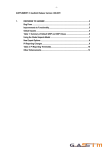
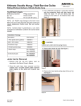
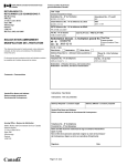
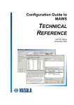
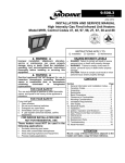
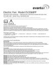
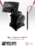
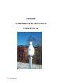
GEONOR
T-200B PRECIPITATION GAUGE
USER MANUAL
Rev: GU 20030829
TABLE OF CONTENTS – T-200B PRECIPITATION GAGE
INTRODUCTION – PRECIPITATION GAUGE 1 .................. 4
1.1. Principle of Operation.............................................................................4
1.2. Why it is used..........................................................................................4
1.3. Advantages..............................................................................................4
INSTALLATION 2 .................................................................................5
2.1. Locate gauge away from structures and objects .....................................5
2.2. Plan height of collection orifice..............................................................5
2.3. Foundation considerations ......................................................................5
2.4. Pedestal installation ................................................................................6
2.5. Precipitation gauge installation...............................................................7
2.6. Electrical hookup ....................................................................................8
2.7. Antifreeze as needed ...............................................................................9
2.8. Hydraulic Oil to Eliminate Evaporation .................................................10
2.9. Loosen Setscrew on transducer...............................................................10
2.10. Replace gauge cover .............................................................................10
2.11. Install Alter Type Windshield (see Section 4).....................................10
2.12. Hook up data logger and begin readings...............................................10
REFERENCES 3......................................................................................11
MOUNTING INSTRUCTIONS FOR WIND SHIELD 4 .............12-15
MAINTENANCE 5.................................................................................16
5.1. Tools needed ...........................................................................................16
5.2. Service interval .......................................................................................16
5.3. Servicing .................................................................................................16
5.4. Check the function of the transducer ......................................................17
5.5. Removing and replacing transducer........................................................17
5.6. Rust protection maintenance...................................................................18
PARTS LIST 6............................................................................. 19
2
DRAWINGS / DIAGRAMS / FIGURES 7 ......................................20
7.1. Gauge – vertical cross section – shows parts..........................................21
7.2. Electrical hook up of transient arrestor/junction box..............................22
7.3. Alter windshield details ..........................................................................23
7.4. Base plate details.....................................................................................24
7.5. Concrete foundation block......................................................................25
7.6. Gauge with 1m pedestal and Alter windshield .......................................26
7.7. Photograph of installed Precipitation Gauge ..........................................27
7.8. T-200B Gauge Specifications .................................................................28
3
1. INTRODUCTION - PRECIPITATION GAUGE
1.1. Principle of Operation
The T-200B is one of the T-2001 series weighing bucket precipitation gauges. It has a
600-mm (24-inch) capacity. It weighs the precipitation using a precision load cell with a
vibrating wire (VW) transducer. The T-200B gauge uses a standard 12-liter bucket
suspended from 2 chains and the load cell. Each supports 1/3 of the weight. Provided the
gauge is carefully leveled to ensure equal load distribution, 1 load cell will suffice.
The VW transducer was developed in the 1960’s at GEONOR’s then parent research
foundation, The Norwegian Geotechnical Institute (NGI.) Bakkehøi2, et al (1985) used
the VW transducer in the T-200 gauge to measure rain and snow precipitation. NGI
developed the gauge due to need for an automatically recording snow gauge for avalanche
research.
1.2.Why it is used
Since its introduction in 1985, based on the results of extensive tests approved by the
WMO in Scandinavia it was adopted by the several Scandinavian meteorological
institutes (weather services). Starting in the late 90’s U.S. and Canadian agencies have
tested the gauge extensively with good results. Consequently it has seen increasing use in
North America.
1.3. Advantages
The VW transducer has certain advantages over other types of load transducers in
precipitation gauges: (1) It has little temperature sensitivity, (2) good accuracy – better
than 0.1% of full scale, (3) good resolution – better than 0.01% of full scale, (4) long-term
drift free performance – measured by 27-year tests at NGI, (5) compared to gauges that
output analog voltage and current signals, its pulse signal can transmit much farther along
a cable without error, (6) it has an advantage over tipping bucket type gauges with respect
to resolution, measurement of intensity and no moving parts, (7) low power consumption
makes it suitable for use in remote locations where batteries must be charged by solar
panel or wind generator, (8) it uses a 2-wire cable with power supply and signal
superimposed, and (9) its pulse signal is easy to log to a variety of data acquisition
systems.
1
2
Currently the T-200 series includes: T-200B, T-200B3, T-200BW, T-200BP models.
See References – Section 3.
4
2. INSTALLATION
2.1. Locate gauge away from structures and objects
For best results locate the gauge where the wind is least affected by structures and objects,
i.e., as far as possible from walls, buildings, cliffs, and trees, etc. Generally at least a 45°
cone from the top of the inlet orifice should be open to the sky.
2.2. Plan height of collection orifice
Mount the gauge so the inlet orifice is a minimum of 50 cm (20 inch) above the maximum
anticipated snow depth, and 1.75 m (70 inch) over the ground for moderate conditions.
With the 1-m pedestal flush with the ground surface the T-200B orifice will be at 1.75 m.
For deeper snow a 2.5-m pedestal is available as an option.
2.3. Foundation considerations in soil, on rock, or a structure
IMPORTANT: a rigid pedestal and foundation are needed for proper
gauge performance
Regardless of whether the pedestal is installed in soil, on rock or on a structure, the
pedestal must be rigid enough to prevent movements and vibrations due to wind, frost
heave, etc.
2.3.1. Anchor bolts for concrete and rock
The pedestal will be attached to the to the foundation block (or rock) with 4
anchor bolts oriented in a cross, North – South & East – West. Make sure bolts
are vertical with 300-mm between N - S bolt and 300-mm between E - W bolt. .
(see Fig. 7.5). A wood template can be helpful in positioning the anchor bolts,
also shown on Fig. 7.5.
2.3.1.1. Align anchor bolts on N-S & E-W axes.
To minimize diurnal variations the anchor bolts should be aligned on N-S
and E-W axes. (See Fig. 7.5.)
2.3.1.2. Anchor bolt size, length & material
Use 20-mm or 7/8” Ø anchor bolts. Thread sizes are metric M20x2 or U.S.
customary (7/8-12 UNC). Use a minimum length of 375 mm (15-inch)
with minimum 150 mm (6-inch) of the thread above the foundation
surface.
5
2.3.2. Foundation in soil
You need to size a concrete foundation (see Fig. 7.5.) block to anchor the pedestal.
The size depends on the strength of the soil, frost depth, wind and other factors in
your location. Movement of the concrete foundation due to i.e., frost heave can
cause the pedestal and gauge to tilt and lead to errors in the data and damage to the
vibrating wire.
2.3.2.1. Excavation depth
Excavate for the concrete foundation block deep enough to avoid
movement from frost heave or dynamic forces caused by wind, etc. As a
general guideline excavate 600 to 1000 mm deep.
2.3.2.2. Size of concrete block foundation
The height of the block can extend from flush with the ground to any
required height depending on expected snow depth. A typical concrete
foundation block width is 600-mm (2-ft) square. .
2.3.3. Foundation on rock
On a competent rock surface, drill holes for anchor bolts (see sec 2.3.1.). Grout
the anchor bolts in place at minimum depth of 200 mm. Make sure there is
sufficient thread to mount the reaction nuts, pedestal and clamping nuts (see Fig.
7.6.).
2.4. Pedestal Installation
IMPORTANT: Please note that a stable pedestal is essential for accurate
data. If the pedestal is allowed to vibrate your data may degrade and
the vibrating wire may break. Tilting of the gauge will also affect your
data and may eventually damage the vibrating wire.
2.4.1. Pedestal details
We recommend the T-200B gauge be mounted on a GEONOR pedestal.
GEONOR provides galvanized steel pedestals in 2 heights (1 m and 2.5 m);
however, you can mount the gauge on any type of pedestal rigid enough to avoid
damage from vibrations. The top of the pedestal must have 3 tapped M8x1 holes
to fit the bolts that connect the gauge to the pedestal.
2.4.2. Installing pedestal
Place the pedestal brackets over the anchor bolts so the triangle pattern of the 3
boltholes on the top of the pedestal points east or west. Install counter nuts and
6
washers on anchor bolts below the pedestal brackets to provide a level surface.
Mount the pedestal so the anchor bolts carry the entire weight of the gauge. Install
the upper washers and nuts. Tighten nuts and check that the pedestal is level.
2.5. Precipitation gauge installation
2.5.1. Remove gauge cover
The gauge cover is one piece that includes the inlet orifice and inlet cone. To
remove the cover, release the 3 clamps around the periphery. NOTE: Press wire
hook sections into locking lugs to keep hooks from falling down and catching on
base when you lift the cover. The cover has a snug fit over the components inside
the gauge. Lift it straight up to clear the components.
2.5.2. Place base (mounting flange) on pedestal
The cast steel base has an M20x1.5 cable gland (strain-relief connector). This fits
cable diameters between 6 and 12 mm (¼ and ½ inch). A drip ring is cast into the
base so that external water runs off, to protect the pedestal.
2.5.3. Align holes to minimize diurnal variations in data
When the sun heats the pedestal it bends very slightly so that the gauge tilts away
from the hot side. To minimize this diurnal effect on readings, align the holes so
that the gauge sensor is on an east-west axis. (See Section 2.4.2.)
2.5.4. Insert gauge mounting bolts
Insert the 3 M8x1 bolts through the holes in the base of the gauge and through the
level adjustment screws that come already installed in the base. Do not tighten.
Leave room to adjust. Level the gauge using the hand level provided. Adjust
leveling screws as needed. When the gauge is level tighten the 3 gauge mounting
bolts.
2.5.5. Install transducer & support chains
IMPORTANT: Please note that the VW load cell has a locking setscrew to prevent damage to the vibrating wire when installing and
servicing the gauge. This setscrew must always be tightened
during installation, removal, service, transport or shipping.
Install VW load cell in the square hole with a round hole beside it. This hole is for
the VW load cell cable. Install chains in other square holes. Connect chain Shooks to bucket support dish.
7
2.5.6. Install bucket in support dish
Align mark on bucket (indented punch mark on rim) with the location of the VW
load cell. This is to ensure correct calibration when the bucket is removed and
replaced. Carefully place the bucket in the support dish. To level the bucket, use
the level provided and adjust the black knurled nuts on the chains and VW load
cell. Take cross-readings to check level. This is important to minimize errors in
the data.
2.6. Electrical hookup
2.6.1. Hook up cable from VW Load Cell to Transient Arrestor
Run the cable from VW load cell through hole in the rim to green transient
arrestor box mounted on the bucket support rim. Hookup the red cable (+) to
terminal 6, and the black (-) cable to terminal 4.
IMPORTANT: Take great care to ensure that the cable does not
come in contact with the suspended parts. This can lead to
inaccurate readings.
2.6.2. Connect cable from transient arrestor to data collection terminal
We recommend a two-wire shielded cable with cross-section area of leads of 0.5
mm² (20 AWG). The cable must be suitable for the environment to which it will
be exposed. Geonor supplies a standard model P-540 cable. (For severe
environments we recommend GEONOR P-430 armored cable).
Pass the cable through the cable gland (strain-relief connector) on the base of the
gauge. Do not allow cable to contact support dish or bucket. Use cable ties or
adhesive tape. Run cable through opening in bucket support rim. Hookup the
positive cable to terminal 5 and the negative cable to terminal 3. (See Fig. 7.2.)
Pull out cable slack and tighten the cable gland. The transmission distance
between gauge and data collection terminal can be up to 1 km. (3000 ft)
2.6.3. Over voltage protection – ground
Connect the shield to terminal 1 on the transient arrestor. Connect the shield cable
to ground at the opposite end.
2.7. Add antifreeze as needed
When the gauge is operating below 0°C, an antifreeze blend must be added to the bucket
to melt frozen precipitation and to prevent freezing.
It is important to notice that the capacity of the collected precipitation is decreased when
8
antifreeze is added. The antifreeze becomes a part of the total volume collected. Two
types of antifreeze include (1) Ethylene glycol and (2) the more environmentally friendly
Propylene glycol.3 Methanol is added to adjust the density of the antifreeze to provide
rapid melting. Tables in the following sections show the amount of antifreeze needed to
keep the collected precipitation from freezing at various temperatures.
2.7.1. When using Ethylene glycol & methanol
Ethylene glycol mixture is toxic. It should be drained into a plastic container for disposal according to appropriate
regulations.
Fig. 2.7.1.
Min.
temperature
before freezing,
0°C
-5°C
-10°C
-15°C
-20°C
-25°C
-30°C
-35°C
Ethyleneglycol, liter
Methanol, liter
Precipitation
capacity, mm
0.0
0.6
1.0
1.5
1.7
2.0
2.3
2.4
0.0
0.9
1.6
2.1
2.5
3.0
3.3
3.6
600
525
470
420
390
350
320
300
Collected
volume
capacity, liter
12.0
10.5
9.4
8.4
7.8
7.0
6.4
6.0
2.7.2. When using ETI Blend of propylene glycol/methanol/glycerine
Fig. 2.7.2.
Min. temperature
before freezing,
ETI blend, liter
0.0
0°C
1.5
-5°C
2.8
-10°C
3.4
-15°C
4.4
-20°C
5.0
-25°C
5.3
-30°C
5.7
-35°C
2.8. Add Hydraulic Oil to Eliminate Evaporation
Precipitation
capacity, mm
600
525
460
430
380
350
335
315
Collected
volume
capacity, liter
12.0
10.5
9.2
8.6
7.6
7.0
6.7
6.3
It is essential to add 0.4 liters thin oil, winter and summer, to retard evaporation losses.
We recommend Esso (Exxon) UNIVIS J13 aero hydraulic oil due to its very low
solidification point. You can also use other oils with a density less than water that do not
3
Check with local regulations regarding disposal.
9
become viscous in the temperature range anticipated. Change the oil at least once a year
to avoid deterioration, which will result in increased evaporation.
2.9. Loosen Setscrew on transducer
Unscrew the setscrew at least 4 revolutions to keep it clear of the vibrating wire. It may
be left in place while the gauge is collecting data. If left in place, make sure to wrap a
piece of tape around it to make sure it will not come in contact with the vibrating-wire.
If possible, at this point it is recommended to make sure you have a good signal.
2.10. Replace gauge cover
2.11. Install Alter Type Windshield (see Section 4)
To prevent undesirable effects of wind turbulence around the gauge, a windshield must be
installed.
Important: Install the Alter type windshield 13 mm above the top of the
T-200B orifice.
The GEONOR pedestal has windshield mounts on the pedestal. This provides the
specified 13-mm height above the top of the gauge orifice. (See Section 4.)
2.12. Hook up data logger or manual read-out unit and begin readings
The transducer should make an audible sound on applying electrical power to the system.
Vibration frequency runs from about 1000 Hz with an empty bucket to around 3000 Hz
with a full bucket.
To calculate precipitation from frequency we use the following formula (see calibrations
certificates):
P = A ( f – f0 ) + B ( f – f0 )²
Where:
P
A&B
f0
f
= precipitation (calibration certificates show precipitation in cm)
= transducer calibration constants
= transducer frequency with empty bucket - (zero frequency)
= transducer frequency
3. REFERENCES
10
Bakkehøi, Steinar; Kjell Øien and E. J. Førland (1985) An Automatic Precipitation Gauge
based on Vibrating-Wire Strain Gauges, Nordic Hydrology No. 16, pp. 193-202
Tunbridge, Lloyd and Kjell Øien (1988) The advantage of Vibrating Wire Instruments in
Geomechanics, 2nd Intl. Symposium on Field Measurements in Geomechanics, Balkema,
Rotterdam, ISBN 90 6191 7786. Also publ. In Norwegian Geotechnical Institute (NGI)
internal report 55100-7 April 1987.
11
4. MOUNTING INSTRUCTIONS FOR WIND SHIELD
All dimensions are in mm unless specified
Measure and mark 500 mm from the threaded end on the horizontal pipes.
(The horizontal pipes do not have slots cut out of the threads.)
The distance from underneath the stop pin to the top of the vertical tube is 817 mm.
The stop pin needs to be hammered into the pre-drilled hole.
(Reduceing the diameter of the pin slightly by squeezing or hammering to will make it
easier to get started)
12
Screw in the horizontal tubes.
Slide the Kee-clamps on as shown until they coincide with the 500 mm mark
(Make sure all vertical holes are on the same side, on the right or the left).
Align the clamps vertically.
13
Place the 4 vertical pipes in the Kee-clamp openings with cutout section at top, Slide
pipes down until the stop pin rests on Kee-clamp. The cutout section should not face
the gauge. (This is where the wind shield ring will rest)
Lay out the 4 shield ring segments.
Install blades and spacers with channel of blade facing out (the 4 couplings for the
shield ring act as spacers and the 4 areas for mounting on vertical tubes act as
spacers).
14
Place the ring carefully in the vertical slots in the vertical tubes.
Screw on the four 1” tube caps and tighten so the caps grip the ring.
Make final adjustments if necessary, and retighten all screws.
Ensure that the upper end of the windshield blade approximately 13 mm
(1/2 inch) higher than top of the inlet orifice.
15
5. MAINTENANCE
5.1. Tools needed
•
•
•
•
•
•
•
•
Level, 300-mm long
Screw driver, 4-mm blade
Adjustable spanner (wrench) 0-27 mm
Container for disposal of anti-freeze mixture (12 liter minimum)
Funnel
Measuring cup, 1 liter
5-liters of water
Rubber tubing, approx. 2-m (6-ft) x 13 mm (1/2-inch) ID for siphon. Alternatively
electric drill pump, and suitable tubing
5.2. Service interval
Service the gauge whenever the bucket needs to be emptied. Inspection is recommended
at least 2 times a year.
5.3. Servicing
Disengage the 3 spring toggle fasteners holding the gauge cover to the base and remove
the housing (see Section 2.5.1.). Tighten the setscrew of the transducer to avoid damaging
the vibrating wire.
Use a siphon pump or an electric pump to empty the bucket. Remember to place the
receptacle at a lower level than the bucket. Pump the siphon until flow starts.
IMPORTANT: Do not suck on tube. Antifreeze mixtures are toxic.
In absence of a suitable siphon or pump, you can empty the bucket by hand. Be very
careful not to overload the VW load cell. Use extreme care, so as not to damage the
vibrating wire. Be sure to tighten the setscrew first.
To re-level the gauge, slacken the 3 M8x1 bolts. (See Section 2.5.4.) Level the gauge
using the hand level provided. Adjust leveling screws as needed. When the gauge is
level, tighten the 3 gauge mounting bolts.
Clean out the bucket. Replace the bucket carefully in the weighing dish. Remember to
align the dot on the rim of the bucket with the one on the support rim.
Add required quantity of anti-freeze mixture and anti-evaporation oil. Loosen the
setscrew on the transducer. Replace the gauge cover and lock the 3 toggle clamps.
16
5.4. Check the function of the transducer
Empty bucket check
Level the bucket accurately (see Sections 2.5.4 & 2.5.6.). Check the frequency
with an empty bucket (fo-value). Use the data logger or a GEONOR frequency
counter4. Compare with the f0-value on the calibration certificate for the
transducer. If the difference is equal or less than 10 Hz no adjustment is
necessary. If the difference exceeds10 Hz, calculate a new value for constant A.
Use the new f0 and the new A in your calculations.
Formula for calculating a new constant A with new fo
A' = A + 2B(f0' – f0)
Where A' and f0' are new values, and A, B and f0 are the original calibration
values. (See Section 2.13. or calibration sheet)
Check with precipitation in the bucket
Fill the bucket with 1-kg of water. If the water is free of air this equals a volume
of 1 liter. (Water from the tap can contain considerable air, which must be taken
into account. Boiling for 10 minutes can remove most of the air.) 1 kg (1 liter) of
water represents exactly 50 mm of precipitation. Recalibrate the transducer if it
differs by more than 0.5% from the value on the calibration sheet. GEONOR
offers factory recalibration service.
5.5. Removing and replacing transducer
•
•
•
•
•
•
•
Remove gauge cover
Tighten setscrew on VW load cell
Lift out bucket carefully
Disconnect electrical leads from the transient arrestor
Unhook the S-hook from the bucket support dish
Hold the VW load cell and remove knurled nut from top of adjustment screw
Remove the VW load cell from square guide in the bucket support rim.
Install a new VW load cell in the reverse order (see Section 2.5.5.)
IMPORTANT: Loosen the setscrew before replacing the gauge cover.
4
GEONOR model P-520M portable frequency counter.
17
IMPORTANT: The bucket support dish must be free to swing in all
directions without noticeable resistance. Resistance in the support links
can contribute to error especially with low weights in the bucket.
When fitting a new transducer to the weighing system, use the new
values for A, B and f0. These are given in the calibration sheet
accompanying the transducer.
5.6. Rust protection maintenance
For added protection, apply two layers of a rust preventing coating such as paint, zincgalvanizing spray or similar on all threaded parts of the pedestal and windshield.
18
6. PARTS LIST
Item code
Description:
470000
471000
PRECIPITATION GAUGE
T-200B Precipitation Gauge, 1 sensor
T-200B3 Precipitation Gauge, 3 sensor option
470001
470004
470009
470010
PRECIPITATION GAUGE, PARTS
Base Plate/Mounting Flange, (cast aluminum)
Gauge cover, (aluminum)
Bucket
Bucket support dish
470800
470013
470014
455020
470021
PRECIPITATION GAUGE, ACCESSORIES
Sensor, Vibrating Wire Transducer
Adjustment set, upper (screws, chain & S-hook)
Adjustment set, base, 3 pieces req.
Junction box w/transient arrestor
Level, for precipitation gage
470250
ALTER SHIELD
Alter Shield, complete
470202
470205
470203
470204
470206
470207
470208
470209
ALTER SHIELD, PARTS
Spacer piece (qty: 24)
Segment blade (qty: 32)
Connector, (qty: 4)
Setscrews for connector, (qty: 8, 2 on each connector)
Kee-clamp, (qty: 4)
Vertical pipe post, for windshield (qty: 4)
Horizontal pipe brace, for windshield (qty: 4)
Cap nut for top of vertical pipe post, for windshield (qty: 4)
Stop-pins for horizontal pipe brace (qty: 4)
Cir-clips (qty: 4)
Plastic cable holders (qty: 4)
470210
470212
Unbraco key (Allen wrench), 4-mm for windshield
Unbraco key (Allen wrench), ¼", for windshield
470400
470450
PEDESTAL
Pedestal, 1.0 m, galvanized
Pedestal, 2.5 m, galvanized
450000
PORTABLE READOUT UNIT
P-520M Read-out Unit for VW Sensors, portable w/ charger. 100 x 200x 25 mm.
455000
461000
INTERFACE, Hybrid Circuit
The TH-501 interface amplifies and converts the sine wave output of a GEONOR
VW transducer to a square wave. This facilitates data logging. The TH-501 is a
stand-alone circuit board (20 x 35 mm). It is normally supplied in a box with 35-mm
DIN rail clips for easy mounting in a field terminal box. Versions of the TH-501
provide a 0-5 V (455050A) or –2.5 to +2.5V square wave output (455055B). There
is an option (455060C) to switch on/off the VW transducer between readings to
conserve power.
CABLE
P-540 Cable, Standard cable 10-mm Ø, 2-wire, double PE jacket, braided shield.
19
7. DRAWINGS / DIAGRAMS / FIGURES
7.1. T-200B Gauge – vertical cross section – shows parts ........................21
7.2. Electrical hook up of transient arrestor/junction box .......................22
7.3. Electrical hook up of TH-501B Hybrid………………………………23
7.3. Alter-shield details…………………………………………………….24
7.4. Base plate details………………………………………………………23
7.5. Concrete foundation block……………………………………………24
7.6. Gauge with 1m pedestal and Alter windshield………………………25
7.7. Photograph of installed Precipitation Gauge………………………..26
7.8. T-200B Gauge Specifications…………………………………………27
20
21
22
23
24
25
26
27
28
29