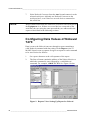
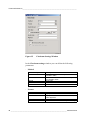
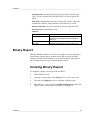
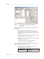
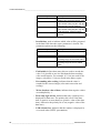
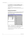
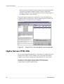
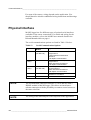
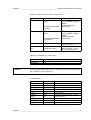
1
Configuration Guide to MAWS TECHNICAL REFERENCE M210511EN-A November 2005 PUBLISHED BY Vaisala Oyj P.O. Box 26 FIN-00421 Helsinki Finland Phone (int.): +358 9 8949 1 Fax: +358 9 8949 2227 Visit our Internet pages at http://www.vaisala.com/ © Vaisala 2005 No part of this manual may be reproduced in any form or by any means, electronic or mechanical (including photocopying), nor may its contents be communicated to a third party without prior written permission of the copyright holder. The contents are subject to change without prior notice. Please observe that this manual does not create any legally binding obligations for Vaisala towards the customer or end user. All legally binding commitments and agreements are included exclusively in the applicable supply contract or Conditions of Sale. _________________________________________________________________________________ Table of Contents CHAPTER 1 GENERAL INFORMATION............................................................................ 5 About This Manual ................................................................... 5 Contents of This Manual ....................................................... 5 Version Information ............................................................... 6 Related Manuals ................................................................... 6 Feedback............................................................................... 7 General Safety Considerations ............................................. 7 Recycling................................................................................... 7 Trademarks ............................................................................... 8 License Agreement .................................................................. 8 Technical Support .................................................................... 8 CHAPTER 2 CONFIGURING OPTIONAL HARDWARE .................................................... 9 Digital I/O Module ..................................................................... 9 Configuring Digital I/O Module QMI108 ................................ 9 Nokeval 7470 Serial to Analog Converter ............................ 12 Configuring Communication Port of Nokeval 7470 ............. 13 Configuring Data Values of Nokeval 7470 .......................... 16 Scaling of Data............................................................... 18 Handling of Invalid Data ................................................. 18 Timing of Reports........................................................... 19 Error Indicator ................................................................ 19 CHAPTER 3 MANAGING SETUPS................................................................................... 21 Setup Memory Size ................................................................ 21 Executing a Setup File from Compact Flash Memory Card21 Executing an Alternative Setup File from Compact Flash Memory Card .......................................................................... 25 CHAPTER 4 CONFIGURING COMMUNICATION OPTIONS........................................... 29 Iridium Satellite Transmitter.................................................. 29 Configuring Iridium Transmission........................................ 30 Iridium Configuration Options.............................................. 34 CHAPTER 5 CONFIGURING CALCULATIONS AND REPORTS ................................... 37 Accumulator with Predefined Reset Time ........................... 37 VAISALA_________________________________________________________________________ 1 Technical Reference_________________________________________________________________ Configuring Accumulator .....................................................38 Resetting Accumulator Manually.........................................40 Using the Accumulator Variable in Reports.........................41 Power Control Option ............................................................41 Configuring Power Control Option.......................................42 Timer Option ...........................................................................43 Configuring Timer Option ....................................................43 Enhanced Time Snapshot......................................................44 Checksum Option in Reports ................................................45 Creating Checksum Report .................................................45 Binary Report ..........................................................................49 Creating Binary Report ........................................................49 CHAPTER 6 CONFIGURING SENSORS ..........................................................................55 Vaisala Weather Transmitter .................................................55 Configuring Vaisala Weather Transmitter WXT510 ............56 Communications Setup ..................................................56 Configuring the Sensor...................................................56 Using Sensor Variables in Reports ................................61 Gill's WindSonic......................................................................62 METEK's 3D Ultrasonic Anemometer...................................62 Configuring Ultrasonic Anemometer USA-1........................64 Communications Setup ..................................................64 Configuring the Sensor...................................................64 Using Sensor Variables in Reports ................................66 Vaisala Wind Vane ..................................................................68 Installing Wind Vane WAV151 ............................................68 Vaisala HUMICAP Humidity and Temperature Transmitters HMT330 Series .................................................72 Configuring HMT330 ...........................................................72 Using HMT330 Variables in Reports ...................................75 Temperature Measurement PT1000 ......................................76 Temperature Measurement PT100 in 3-Wire Connection...78 Absolute Shaft Encoder.........................................................78 Configuring Absolute Shaft Encoder QSE104.....................79 Setting Current Water Level for Absolute Shaft Encoder....81 Setting Current Water Level for Multiple Sensors ..........81 Geonor Water Gauge..............................................................82 Configuring Geonor Water Gauge T-200B3........................87 Output Parameters ..............................................................88 Rim Heating.........................................................................90 Selecting and Configuring HeatControl Component ......91 Hydra Sensor HYD-10A..........................................................94 Lambrecht QUATRO-IND .......................................................95 Configuring Lambrecht QUATRO-IND ................................95 Communications Setup ..................................................95 Configuring the Sensor...................................................95 Sensor Monitoring ........................................................100 2 ____________________________________________________________________ M210511EN-A _________________________________________________________________________________ CHAPTER 7 CONFIGURING SERIAL SENSOR INTERFACES.................................... 103 Physical Interface................................................................. 104 Data Acquisition Methods ................................................... 105 Configuring Serial Line Parameters ................................... 106 Configuring Sensor Interface.............................................. 108 Serial Sensor Interfaces ...................................................... 112 Present Weather Sensors PWD11, PWD21 and FD12P.. 112 Ceilometers CL31, CT25K and CT25KAM ....................... 114 Digital Barometer PTB220 ................................................ 116 Ultrasonic Wind Sensor WS425........................................ 118 WT500 Series Wind Transmitters ..................................... 119 GARMIN GPS35-PC GPS Receiver ................................. 121 CHAPTER 8 ALARMS..................................................................................................... 123 Output Control Using Alarm................................................ 123 CHAPTER 9 ADDITIONAL FEATURES ......................................................................... 127 Floating Point Numbers in Static Parameters ................... 127 Enhanced Generic Frequency Measurement .................... 127 Passive FTP Mode with iConnector ................................... 128 APPENDIX A SENSOR STATUS LIST ............................................................................ 131 INDEX ......................................................................................................... 133 VAISALA_________________________________________________________________________ 3 Technical Reference_________________________________________________________________ This page intentionally left blank. 4 ____________________________________________________________________ M210511EN-A Chapter 1 _________________________________________________________ General Information CHAPTER 1 GENERAL INFORMATION About This Manual This manual is intended for the users of MAWS Automatic Weather Station. It provides information for creating MAWS setups with more advanced features of MAWS Lizard and is thus supplementary to MAWS Lizard Setup Software User's Guide and other MAWS user's guides. Contents of This Manual This manual consists of the following chapters: - Chapter 1, General Information, provides important safety, revision and technical support contact information, as well as information on related documentation. - Chapter 2, Configuring Optional Hardware, contains information needed when configuring optional hardware. The optional hardware described in this chapter includes Vaisala Digital I/O Module and Nokeval 7470 Serial to Analog Converter. - Chapter 3, Managing Setups, provides additional information on setup management. - Chapter 4, Configuring Communication Options, chapter provides information on the Iridium satellite transmitter communications option, how to interface the Iridium satellite transmitter to MAWS, and how to use the Short Burst Mode in binary transmission. VAISALA_________________________________________________________________________ 5 Technical Reference_________________________________________________________________ - Chapter 5, Configuring Calculations and Reports, provides additional information on configuring different MAWS Lizard calculations and reports. - Chapter 6, Configuring Sensors, provides advanced information on configuration and measurement control for different sensors. - Chapter 7, Configuring Serial Sensor Interfaces, contains information needed when configuring serial sensor interfaces, that is, connecting sensors that use serial communications to the MAWS301 weather station. Note that this chapter contains only instructions for configuring the interface, not the sensor itself. - Chapter 8, Alarms, provides information on output control using alarms. - Chapter 9, Additional Features, provides information on other features or enhancements to MAWS Lizard. - INDEX Version Information Table 1 Manual Code M210511EN-A Manual Revisions Description This manual. Applicable for MAWS Lizard and Terminal and MAWS logger QML201 software from version 5.02 onwards. Related Manuals Table 2 Manual Code M010141EN M210662EN M010114EN M210708EN M210630EN Related Manuals Manual Name MAWS Lizard Setup Software - User's Guide Vaisala HydroMet™ System MAWS301 - User's Guide Vaisala HydroMet™ System MAWS301 Installation Manual Vaisala HydroMet™ System MAWS100 - User's Guide Automatic Weather Station MAWS201 - User's Guide Related information can also be found in several Technical References. 6 ____________________________________________________________________ M210511EN-A Chapter 1 _________________________________________________________ General Information Feedback Vaisala Customer Documentation Team welcomes your comments and suggestions on the quality and usefulness of this publication. If you find errors or have other suggestions for improvement, please indicate the chapter, section, and page number. You can send comments to us by e-mail: [email protected] General Safety Considerations Throughout the manual, important safety considerations are highlighted as follows: WARNING Warning alerts you to a serious hazard. If you do not read and follow instructions very carefully at this point, there is a risk of injury or even death. CAUTION Caution warns you of a potential hazard. If you do not read and follow instructions carefully at this point, the product could be damaged or important data could be lost. NOTE Note highlights important information on using the product. Recycling Recycle all applicable material. Dispose of batteries and the unit according to statutory regulations. Do not dispose of with regular household refuse. VAISALA_________________________________________________________________________ 7 Technical Reference_________________________________________________________________ Trademarks Microsoft, Windows, and Windows NT are registered trademarks of Microsoft Corporation in the United States and/or other countries. License Agreement All rights to any software are held by Vaisala or third parties. The customer is allowed to use the software only to the extent that is provided by the applicable supply contract or Software License Agreement. Technical Support For technical questions, contact the Vaisala technical support: E-mail [email protected] Fax +358 9 8949 2790 If the product needs repair, please follow the instructions below to speed up the process and to avoid extra costs to you. NOTE 1. Read the warranty information. 2. Contact Vaisala technical support via e-mail or fax and request for RMA (Return Material Authorization) and shipping instructions. 3. Proceed as instructed by Vaisala technical support. RMA must always be requested from Vaisala technical support before returning any faulty material. 8 ____________________________________________________________________ M210511EN-A Chapter 2 ________________________________________________ Configuring Optional Hardware CHAPTER 2 CONFIGURING OPTIONAL HARDWARE This chapter contains information needed when configuring optional hardware. The optional hardware described here includes Vaisala Digital I/O Module and Nokeval 7470 Serial to Analog Converter. Digital I/O Module Digital I/O Module QMI108 is used to extend the I/O capacity of MAWS. It is equipped with eight inputs and eight outputs. It interfaces to the logger via the SPI connector. The module is located inside the MAWS enclosure beside the MAWS logger, and it conforms to the same environmental immunity and emission standards as the logger. For further information on the module, refer to Vaisala HydroMet System MAWS301 User's Guide. Configuring Digital I/O Module QMI108 1. Add the Digital I/O Module QMI108 to the setup in the Hardware Setup view of MAWS Lizard. You can also select which outputs are controlled by timers and name the outputs in the Description for... text boxes, see Figure 1 on page 10. VAISALA_________________________________________________________________________ 9 Technical Reference_________________________________________________________________ 0506-036 Figure 1 2. Hardware Setup View: Digital I/O Configuration Proceed to the Timers view to configure the on/off cycle for the selected outputs (0 and 4). See Figure 2 below for an example of the Timers view: 0506-037 Figure 2 Timers View: Timer Configuration for the Digital Outputs 10 ___________________________________________________________________ M210511EN-A Chapter 2 ________________________________________________ Configuring Optional Hardware In the example, the configuration is as follows: - Test output 0 toggles between on and off in a one-minute cycle. - Test output 4 is on for one minute before each full hour. Alternatively, you can control the outputs with alarms, for example, by activating the output signal when the alarm condition is met. Proceed as follows: 1. Configure the alarm condition in the Alarms view, see Figure 3 below for an example: 0506-038 Figure 3 Alarms View: Controlling Digital Output Using Alarm In the example, the configuration activates output 3 when the air temperature measured by the QMH101 sensor rises above +15 °C. The inputs of the Digital I/O Module can be used like any other application variables, that is, - for reporting, - for logging, - as an alarm input. VAISALA________________________________________________________________________ 11 Technical Reference_________________________________________________________________ In the Reports view, the input statuses are available as individual variables IN0 through IN7 and combined as bits into a single status word ALL. The input module status is also available as for the sensors, refer to Figure 4 below. 0506-039 Figure 4 Reports View: Digital Inputs in the Report Nokeval 7470 Serial to Analog Converter 0412-045 Figure 5 Nokeval Serial to Analog Converters Nokeval 7470 Serial to Analog Converter is used for converting a predefined ASCII message to one or more voltage or mA outputs. This kind of conversion may be required, for example, when weather information is needed in automation systems where only voltage or 12 ___________________________________________________________________ M210511EN-A Chapter 2 ________________________________________________ Configuring Optional Hardware current inputs are used instead of a serial data interface. The converter can be controlled through an RS-485 serial line. As Nokeval converters are fully configurable, knowledge on these devices is required before taking them into use with MAWS. It is possible to add one or more converters to a single RS-485 serial line with MAWS. For further details, see the applicable Nokeval user's manual, available at www.nokeval.com. Configuring Communication Port of Nokeval 7470 One or several Nokeval devices are connected to MAWS through an RS-485 communication port. The device can be connected to the following RS-485 ports: - Integrated RS-485 port (COM1) - DSI485A Isolated RS-485 port (2-wire or 4-wire connection) In the Optional Hardware view of MAWS Lizard, configure the selected RS-485 port as follows: 1. In the Line parameters frame, leave the default values (9600, 8, 1, None), unless the Nokeval device is to be otherwise configured. See Figure 6 on page 14. 2. In the Wiring options frame, select the Two wire connection type from the list (DSI485A only). 3. Leave all options unselected in the Handshake options frame. VAISALA________________________________________________________________________ 13 Technical Reference_________________________________________________________________ 0412-069 Figure 6 4. Hardware View: Configuring Communication Port for Nokeval 7470 (1/2) In the Transmit control frame, select Transmit control enabled and set the timing as follows in the editable text boxes, see Figure 7 on page 15: - Start delay (ms): 30 - End delay (ms): 10 14 ___________________________________________________________________ M210511EN-A Chapter 2 ________________________________________________ Configuring Optional Hardware 0412-070 Figure 7 Hardware View: Configuring Communication Port for Nokeval 7470 (2/2) 5. In the Buffers frame, leave the default values. 6. Proceed to the Equipment view, see Figure 8 below: 0506-040 Figure 8 Equipment View: Connecting Nokeval 7470 to Serial Port VAISALA________________________________________________________________________ 15 Technical Reference_________________________________________________________________ 7. NOTE Select Nokeval Converter from the Aux list and connect it to the selected serial port. Add only one Nokeval Converter to the serial port here, even if there are several devices connected to this serial line. Do not connect more than one Nokeval Converter to one serial port in the Equipment view. If there are several devices connected on the serial bus, they are using the same port and they are addressed in the reports as described in the following sections. Configuring Data Values of Nokeval 7470 Data is sent to the Nokeval converter through a report containing a valid Nokeval command with data values. In the Reports view of MAWS Lizard, create a separate StringForm report for each command to be sent. Proceed as follows: 1. Set a space character as the cell separator of the report. 2. The first cell must contain the address of the Nokeval device to which the command is sent, followed by a valid Nokeval command. For example, \x80OUT CH 1. See Figure 9 below: 0506-041 Figure 9 Reports View: Setting Up Report for Nokeval 16 ___________________________________________________________________ M210511EN-A Chapter 2 ________________________________________________ Configuring Optional Hardware Give the address as an 8-bit hexadecimal value where the highest bit is always set. The hexadecimal value is given in the report using the special character code \x. For example, if the device address is 0, then the first report field should start with \x80. If the device address is 2, then the field starts with \x82. 3. Give the Nokeval command, excluding the data value, directly after the address. Note that you may not enter a space or any other character between the address and the command. For detailed information about valid commands, refer to Nokeval user's guide. The subsequent field(s) contain the data value(s) of the command. These may be, for example, measurement or calculation results. For details about invalid data handling and scaling of data, see the sections on page 18. The ETX character and the checksum are automatically added to each command by MAWS and therefore they are not allowed to be included in the report. 4. Proceed to the Communications view. 5. Link the reports to the Nokeval device, see Figure 10 on page 18. VAISALA________________________________________________________________________ 17 Technical Reference_________________________________________________________________ 0506-042 Figure 10 Communications View: Connecting the Report to Nokeval 7470 Scaling of Data All data values must be properly scaled to fit into the output range of the Nokeval converter outputs. You can carry out the scaling using two alternative methods: - Configuring MAWS to scale the data. This is performed using a User definable conversion, configured in the Calculations view of MAWS Lizard. - Configuring the Nokeval converter to scale the data. Refer to Nokeval user's guide for details. Handling of Invalid Data MAWS will not send a command if the data value is invalid, that is, the report includes the character '/'. The Nokeval converter can be configured to invalidate the output if no command has been received within a specified time (see Nokeval user's guide for details). Therefore, the system can be configured so that an invalid data value will invalidate the analog output of the converter. In this case, a separate report should be used to control each analog output, that is, the OUT CH command should be used, instead of the OUT SCAN command. 18 ___________________________________________________________________ M210511EN-A Chapter 2 ________________________________________________ Configuring Optional Hardware Alternatively, any specific data reading can be sent when the data value is invalid, by specifying an invalid data indicator for the data cell in the report. Timing of Reports Up to 32 reports can be generated successively at the same synchronization time. MAWS will queue the commands and process them one by one. If more than 32 reports are needed, the synchronization times of the report generation events must be adjusted so that no more than 32 commands will overlap each other. Error Indicator There is a variable available indicating the number of errors occurred within the previous queue of Nokeval commands, that is, while processing the queue of reports sent at the same synchronization time. When no errors have occurred, this variable has the value 0, otherwise it indicates the number of failed commands. This variable of the NokevalCtrl software component is named fails. It can be used, for example, to generate an alarm in case an error occurs in communication. VAISALA________________________________________________________________________ 19 Technical Reference_________________________________________________________________ Table 3 Nokeval 7470 Specifications Parameter Current output: Outputs Maximum load Voltage output: Outputs Maximum load Accuracy Linearity Temperature effect Response time of output RS-485/RS-232 input DAC conversion Power supply Power consumption Power demand IP protection Mounting Weight Value/Description Common negative wire 0 ... 20 mA, 4 ... 20 mA 600 Ω Common negative wire 0 ... 5 V, 0. ... 10V 1 mA 0.1 % of span 0.06 % of span 0.005 % of span / ºC 4.7 ms + response time 67 % of end value 12.5 ms + response time 93 % of end value 150 ms + response time 100 % of end value Both selectable in terminals Galvanically isolated from outputs Nokeval SCL protocol 12-bit (resolution 4096) 18 ... 28 VDC 30... 110 mA max. 2.6 W 20 DIN rail (35 mm) 140 g 20 ___________________________________________________________________ M210511EN-A Chapter 3 ___________________________________________________________ Managing Setups CHAPTER 3 MANAGING SETUPS This chapter provides additional information on setup management. Setup Memory Size For software version 5.0.1 or higher, the size of the setup memory is 224 kilobytes, allowing you to create also larger setups. The internal logging memory size is 1 638 400. Executing a Setup File from Compact Flash Memory Card With the MAWS software version 5.01 or higher, you can execute a setup file (a configuration) directly from the Compact Flash (CF) card. This is especially useful when testing new configurations. Typically, a MAWS configuration is created using MAWS Lizard and uploaded into the MAWS logger using the MAWS Terminal software. With the MAWS software version 5.01 or higher, you can test new configurations in an alternative way. After you have created a new configuration, you can copy the setup file (or several files) to the CF memory card to be executed in the MAWS logger. This requires that the boot code version of your logger is 4.07 or higher. The boot software is independent of the firmware software. In order to check the boot version, give the SYSINFO command in MAWS Terminal. In case your boot code version is lower than 4.07 and you wish to use this new feature, please contact Vaisala VAISALA________________________________________________________________________ 21 Technical Reference_________________________________________________________________ HydroMet HelpDesk. You will need to send your logger to Vaisala for the update. Currently there are external memory cards available from 32 megabytes (MB) up to hundreds of megabytes. Memory cards over 64 megabytes are not recommended by Vaisala. Cards can be read directly in the PC. Several different types of readers are commercially available: internal PCMCIA reader as well as external readers to be connected to USB or parallel port of a PC. Vaisala recommends the usage of industrial grade 32 MB and 64 MB CF cards from SanDisk, that have been tested to function in harsh environments. Note that the CF memory card must be formatted in MAWS before use. To format the card, insert it into the CF slot of MAWS. Give the EXTFS ERASE command. After the card has been formatted, you can remove it from the slot and carry out the copying of the setup file(s) in your PC. The setup file can be located in any MAWS logger directory but in order not to exceed the maximum path length, Vaisala recommends that you store the file either in the root directory or in the first one below the root. NOTE The maximum number of characters allowed in the path name is eight (8). The maximum number of characters allowed in the file name is eight (8), and the maximum number of characters allowed in the file name extension is three (3), as in MAWS Lizard. If you want to test several configurations, you can copy all of them to the CF card at the same time. However, only one setup file will be executed at a time. In order to test a new configuration by executing the setup file from the CF card, proceed as follows after you have formatted the CF card and copied the setup file: 1. Check that MAWS includes a boot code version 4.07 or higher. Use the VER command or the SYSINFO command to check the version. 2. Insert the Compact Flash card into the Compact Flash slot of MAWS. 22 ___________________________________________________________________ M210511EN-A Chapter 3 ___________________________________________________________ Managing Setups 3. To check that a configuration exists, give the following command in MAWS Terminal. Note that MAWS uses a UNIX/LINUX type file system with only one root and thus automatically mounts the CF card on the /Ext/ directory path. dir /Ext/<pathname> where pathname 4. = The directory used Use the reset command to launch a new startup with the setup file to be tested: reset [delay] /Ext/<setup file> where delay = setup file = The period of time (in seconds) before MAWS resets. The value of the delay parameter can be 0, which causes an immediate reset. The path and filename without drive identification For example, if you have copied the setup501.adc setup file to a directory named test, give the following command to launch the new startup: reset 0 /Ext/test/setup501.adc NOTE Note that the directory separator (/) is not the same as in the DOS prompt. Make sure to enter the pathname as presented in the example above (/Ext/). An example output from MAWS after selecting a setup file to be executed from the CF card is as follows: / W> dir /Ext/TEST VAISALA________________________________________________________________________ 23 Technical Reference_________________________________________________________________ . rwxd 13:11:40 21.03.2005 0 .. rwxd 13:11:40 21.03.2005 0 setup501.adc rw-- 12:26:28 21.03.2005 Files shown: 3 1776 Bytes used: 1776 / W> reset 0 /Ext/TEST/setup501.adc Resetting device in 0 seconds COM0: QML201 Startup - Warm Boot Serial # : Z402074 Hardware : Rev B-001 Software : 5.01 Checksum : 00000000 Boot sw version : 4.07 System RAM : 2048kB Free memory : 1768kB Internal temp. : 23.15'C Active errors : NO Active warnings : NO Piggyback - 0 : DSU232 rev: B serial no: 008232 Piggyback - 1 : DSU232 rev: B serial no: 003523 NEW flash checksum (02400000 to 025FFFFF) is BBCC1130 Found setup /Ext/TEST/setup501.adc Starting to execute setup Setup running ok Quick Reference: You can also copy a setup file to the CF card and take it into use by giving only one command. When entering the following command, MAWS will overwrite the original setup file in the /Cfg directory. The new setup will thus be available after each restart. reset [delay] /Ext/<setup file> copy For example, to copy and to take into use the setup501.adc setup file, give the following command: reset 0 /Ext/test/setup501.adc copy 24 ___________________________________________________________________ M210511EN-A Chapter 3 ___________________________________________________________ Managing Setups Executing an Alternative Setup File from Compact Flash Memory Card You can execute an alternative setup file from the Compact Flash (CF) memory card. This is especially useful when upgrading new configurations remotely. An alternative setup file will be executed if the primary setup file in the /Cfg directory fails. NOTE You must set a specific static parameter to enable this. This also requires that there is a CF memory card in the MAWS logger. Proceed as follows: 1. Check that MAWS includes a boot code version 4.07 or higher. You can use the VER command or the SYSINFO command to check the version. 2. Insert the Compact Flash card into the Compact Flash slot of MAWS. 3. To check that a configuration exists, give the following command: dir /Ext/<pathname> where pathname 4. = The directory used To set a specific static parameter to point to an alternative setup file (script), use the SPSET command. Alternativescript is the name of the static parameter to be used to store the path and filename. SPSET alternativescript /Ext/<setup file> For example, if you want the setup501.adc setup file in the test directory on the CF card to be executed in case the primary (probably remotely downloaded) setup file fails, use the following command: SPSET alternativescript /Ext/test/setup501.adc VAISALA________________________________________________________________________ 25 Technical Reference_________________________________________________________________ To verify that the path is correct, give the SPSET command. An output from MAWS is as follows: / > SPSET alternativescript = /Ext/test/setup501.adc If an error occurs while executing the primary setup file, MAWS will check whether the static parameter alternativescript is set. If so, MAWS will be reset. After the reset, MAWS will check whether an alternative setup file exists. If the alternative setup file exists and is functional, MAWS will execute it. Now you have access to MAWS again and you can replace the erroneous primary setup file with a new one. After the next reset, MAWS will try to execute the primary setup file located in the /Cfg directory. An example output from MAWS when the primary setup file fails is as follows: 26 ___________________________________________________________________ M210511EN-A Chapter 3 ___________________________________________________________ Managing Setups COM0: QML201 Startup - Cold Boot Serial # : Z402074 Hardware : Rev B-001 Software : 5.01 Checksum : 00000000 Boot sw version : 4.07 System RAM : 2048kB Free memory : 1768kB Internal temp. : 23.23'C Active errors : NO Active warnings : NO Piggyback - 0 : DSU232 rev: B serial no: 008232 Piggyback - 1 : DSU232 rev: B serial no: 003523 NEW flash checksum (02400000 to 025FFFFF) is BBCC1130 Found setup /Cfg/failing.adc Verifying setup file CRC (7DD7036A)...OK Starting to execute setup Erroneous setup file Runtime error [line:16] Parameter error 'DSI486_1_0' COM0: QML201 Startup - Cold Boot Serial # : Z402074 Hardware : Rev B-001 Software : 5.01 Checksum : 00000000 Boot sw version : 4.07 System RAM : 2048kB Free memory : 1768kB Internal temp. : 23.23'C Active errors : NO Active warnings : NO Piggyback - 0 : DSU232 rev: B serial no: 008232 Piggyback - 1 : DSU232 rev: B serial no: 003523 NEW flash checksum (02400000 to 025FFFFF) is BBCC1130 Found () setup /Ext/TEST/setup501.adc Starting to execute setup Setup running ok VAISALA________________________________________________________________________ 27 Technical Reference_________________________________________________________________ This page intentionally left blank. 28 ___________________________________________________________________ M210511EN-A Chapter 4 ____________________________________________ Configuring Communication options CHAPTER 4 CONFIGURING COMMUNICATION OPTIONS Iridium Satellite Transmitter This chapter provides information on the Iridium satellite transmitter communications option, how to interface the Iridium satellite transmitter to MAWS, and more specifically, how to use the Short Burst Mode in binary transmission. Iridium transmission using data calls can be used like any other modem. Thus, it has been possible to communicate through Iridium with MAWS in earlier release versions as well. Iridium is the only data solution with a complete coverage of the Earth including oceans, airways, and Polar Regions. Iridium delivers the essential communications services to and from remote areas where no other form of communication is available. The Iridium constellation of 66 low-earth orbiting (LEO), cross-linked satellites operates as a fully meshed network and is the largest commercial satellite constellation in the world. Short Burst mode (SBD) is a mechanism to deliver short data messages over the Iridium satellite network to the Internet. Each SBD message can be up to 1960 bytes in length. For more information about Iridium communication, refer to www.iridium.com. VAISALA________________________________________________________________________ 29 Technical Reference_________________________________________________________________ Configuring Iridium Transmission Iridium transmission is configured using MAWS Lizard. Proceed as follows: 1. Start MAWS Lizard. 2. Open an existing setup in the Setup view or create a new one. 3. Proceed to the Hardware view by clicking Next to configure the serial transmission hardware, see Figure 11 below: 0509-051 Figure 11 Hardware View: Selecting Configuration Options for DSU232 MOD1/1 for Iridium Transmission In this example, MOD1/1 on DSU232 is selected for use with the Iridium sensor. You are recommended to keep the default settings in the Configure frame: Option Service connection enabled Speed Data bits Stop bits Parity Hardware-controlled RTS CTS required for transmission Default Value selected 19200 8 1 None selected selected 30 ___________________________________________________________________ M210511EN-A Chapter 4 ____________________________________________ Configuring Communication options 4. Proceed to the Equipment view by clicking Next. 5. Click Aux to list the communication devices, see Figure 12 below. - Scroll down the Available list for Iridium. - Click the Add button and select Iridium. - Double-click the Connector list for Iridium_modem_1 in the I/O Connections frame in order to select the COM port. - Leave the EXCITATION selection to <None>. 0509-052 Figure 12 Equipment View: Selecting I/O Connection for Iridium Modem 4. Proceed to the Communications view. 6. In the Select Communications frame, link a report to the Iridium mode, refer to Figure 13 on page 32. a. Select the report form from the Available reports list. b. Select a port having Iridium_modem_1 as the device. VAISALA________________________________________________________________________ 31 Technical Reference_________________________________________________________________ c. Click the Link button to make a connection between the report and the Iridium modem. d. Modify the parameters in the Configure frame on the right. 0509-053 Figure 13 Communications View: Configuring Iridium Transmission Parameters In order to adjust the parameters, refer to Configuring Modem Options Technical Reference. As a default, the parameters are set for using Short Burst Data (SBD). There is also a new option for powering the device only when sending a report, see Figure 14 on page 33. 32 ___________________________________________________________________ M210511EN-A Chapter 4 ____________________________________________ Configuring Communication options 0509-054 Figure 14 Communications View: Configuring Iridium Transmission Parameters Using Power Control Option The Powering device option in the Options frame lists all the Power Control components in the setup. For more detailed information on how to use this option, see section Power Control Option on page 41. 7. Select the Short Burst mode in the Report transmission frame by choosing SBD from the Transmission mode list, see Figure 15 on page 34. VAISALA________________________________________________________________________ 33 Technical Reference_________________________________________________________________ 0509-055 Figure 15 Communications View: Selecting Report Transmission Options for Iridium For the other options, make the same selections as for any PSTN modem. The fields Send to (on success and on fail) are currently used only when transmitting via SBD. You should leave the fields empty unless otherwise informed. Iridium Configuration Options There are also configuration options for Iridium. You can view them by clicking Iridium_modem_1 in the Config frame. If the Read clock time from Iridium option is selected, the Iridium clock counter is read when the SBD transmission has been done and MAWS time is set according to this counter, see Figure 16 on page 35. 34 ___________________________________________________________________ M210511EN-A Chapter 4 ____________________________________________ Configuring Communication options 0509-056 Figure 16 Communications View: Selecting Iridium Configuration Options VAISALA________________________________________________________________________ 35 Technical Reference_________________________________________________________________ This page intentionally left blank. 36 ___________________________________________________________________ M210511EN-A Chapter 5 ___________________________________________ Configuring Calculations and Reports CHAPTER 5 CONFIGURING CALCULATIONS AND REPORTS Accumulator with Predefined Reset Time You can use the "Accumulator" component to add a source parameter to the destination parameter in order, for example, to accumulate annual precipitation in the MAWS system and to reset the calculation at a predefined moment. The destination parameter is stored in the static parameters to maintain its value over reset or power shutdown. In addition, the destination parameter can be reset according to a predefined schedule. The Accumulator is always incremented when the source variable is measured. To select the Accumulator component, proceed as follows: 1. In the Calculations view, choose Miscellaneous calculations (Misc) by clicking on the correct button below the Available list box, see Figure 17 on page 38. VAISALA________________________________________________________________________ 37 Technical Reference_________________________________________________________________ 0511-113 Figure 17 2. Calculations View: Selecting the Accumulator Component Select the Accumulator in the list by clicking on the item name and then the Add button. Configuring Accumulator To configure the Accumulator, proceed as follows: 1. In the Calculations view, select a static parameter to be used in accumulation from the Select static parameter combo box which lists all the correct static parameters that are defined in the static parameter sheet. If there is no suitable parameter, you can create a new one by typing it manually in the editable text box. 2. Select the Source component and source Variable from the corresponding combo boxes. The increment source and variable indicate the source parameter to be added to the destination variable. 38 ___________________________________________________________________ M210511EN-A Chapter 5 _________________________________________________________________________ 3. You can also choose a reset option (setting of the static parameter to zero at a selected time) in the Reset time frame. If you select the No reset check box, the destination parameter is incremented indefinitely unless you reset the Accumulator manually. If No reset is unselected, click on the Reset time button to select the resetting schedule. To select the reset schedule, proceed as follows: - Select the date and time for the reset in the corresponding frames of the Select time view. Use the Time base frame to select whether the reset follows Local or UTC time. - Select a reset interval (how often resetting occurs) in the Recurrence options frame. 0504-038 Figure 18 Select Time View: Selecting Accumulator Resetting Schedule If you select reset to occur once an hour, the timing is as with normal timers. If you select reset to occur monthly and the resetting date is the last day of the month, reset always occurs during the very last day regardless of the number of days in that particular month. For example, for February and leap year, the system automatically reschedules the resetting days 30 and 31 to be the 28th or the 29th, depending on the year. In the example above, reset occurs once a year in the 1st of October at midnight. VAISALA________________________________________________________________________ 39 Technical Reference_________________________________________________________________ Resetting Accumulator Manually You can also reset the Accumulator manually, that is, assign a positive initial value of zero or greater than zero to the accumulation. In order to reset the Accumulator when using MAWS Terminal, proceed as follows: 1. Start MAWS Terminal and select the Station Settings option from the Tools menu or click on the Set Station Settings icon in the Toolbar, see Figure 19 below. 2. In the Static Parameters tab of the MAWS Station Settings window, double-click the corresponding Value cell. The parameter is the one that was selected from the Select static parameter combo box or entered manually in the text box in the Configure frame of the Calculations view at the time the Accumulator was configured. Enter the new parameter value and press Enter. Typically the value is 0.0 but any number greater than zero can be used. 0504-039 Figure 19 3. MAWS Station Settings Window: Entering Accumulator Reset Value Manually Click Save to store the new parameter value to MAWS. If you use some other terminal program than MAWS Terminal in order to reset the Accumulator, give the following command: SPSET <static parameter> [initial value] 40 ___________________________________________________________________ M210511EN-A Chapter 5 _________________________________________________________________________ where static parameter = initial value = Name of the static parameter, selected from the Select static parameter combo box or entered manually in the text box in the Configure frame of the Calculations view. The initial value you wish to assign for the accumulation. Always enter the value with one decimal place (for example, 0.0). Using the Accumulator Variable in Reports To use the Accumulator variable, proceed as follows: 1. Select the Reports view. 2. Create a new report or select an existing one to include the Accumulator variables for the Accumulator. 3. Lizard displays the items that are available for the source in question in the Available list box in the Select Variables frame. Note that the variable used in accumulation is located under the source name SParServer. Click on the plus sign in the Select Variables list box to display it. Power Control Option Power Control is used to control the physical output: either the output pin on the extension board (for example QMI108) or an excitation output on the logger. With this option, it is possible to use the same output for several purposes so that the output pin will be active as long as there is one reservation left. For example, several sensors can use common powering without extremely careful synchronization of timing. The Power Control option is located in the Misc list in the Select Calculation frame. For a variety of options, see also the Conv list. VAISALA________________________________________________________________________ 41 Technical Reference_________________________________________________________________ Configuring Power Control Option To configure the Power Control option, proceed as follows: 1. Start MAWS Lizard. 2. Open an existing setup in the Setup view or create a new one. 3. Proceed to the Calculations view to configure Power Control, see Figure 20 below. 4. Click Misc to list the available options. 5. Select PowerCTRL from the Available list and click Add. 8. Select the output to be controlled from the Channel list in the Configuration frame. 0509-057 Figure 20 Calculations View: Configuring Power Control 42 ___________________________________________________________________ M210511EN-A Chapter 5 _________________________________________________________________________ Timer Option Timer is used to create timed events that occur at a predefined time at specific intervals. These events resemble the timers in the Timers view but are more freely configurable to meet specific needs. The Timer option is located in the Misc list in the Select Calculation frame. For a variety of options, see also the Conv list. Configuring Timer Option To configure the Timer option, proceed as follows: 1. Start MAWS Lizard. 2. Open an existing setup in the Setup view or create a new one. 3. Proceed to the Calculations view to configure Timer, see Figure 21 below. 4. Click Misc to list the available options. 0509-058 Figure 21 5. Calculations View: Configuring Timer Select TimerComp from the Available list and click Add. VAISALA________________________________________________________________________ 43 Technical Reference_________________________________________________________________ There are several configuration options in the Configuration frame on the right: Option Repeat times Scale Time Zone Priority Sync time [ms] Trig interval time [ms] Description Defines how many timed events will be created Indicates whether the timed events are tied to absolute time or whether they are relative and only the interval is meaningful Specifies whether UTC or local time is used to calculate the timed events, if the scale selected is Absolute Defines the priority of the timer. Typically, Normal or Slow are the most suitable options. A Fast timer should be used only in timecritical actions. defines the moment that the timed events are tied to (as in Timers view). Specifies the interval between timed events (as in Timers view). Enhanced Time Snapshot In MAWS Lizard version 5.02 or higher, the Time Snap option is capable of returning also UNIX time, if requested. You can use the UNIX time option in MAWS Lizard by selecting it from the Available list under Select Variables in the Reports view, see Figure 22 on page 45. 44 ___________________________________________________________________ M210511EN-A Chapter 5 _________________________________________________________________________ 0509-059 Figure 22 Reports View: UNIX Time Option under Time Snap Checksum Option in Reports With the MAWS software version 5.02 or higher, it is possible to add a checksum into the report that is already in the report configuration. You can also define where the data begins and ends in the checksum calculation as well as format the checksum fields to meet your own requirements. Creating Checksum Report To use the checksum option in a report, proceed as follows: 1. Start MAWS Lizard. 2. Open an existing setup in the Setup view or create a new one. 3. Proceed to the Reports view to configure a checksum report. 4. Open the available variables in the Select Variables frame. The configurable report in this example is MyReport, see Figure 23 on page 46. VAISALA________________________________________________________________________ 45 Technical Reference_________________________________________________________________ 0509-060 Figure 23 Reports View: Configuring New Checksum Report There are new variables in the list that are used for calculating and showing the checksum: - CRC returns the checksum to be formatted in a User format - CRC_start indicates the start of data to be included in the CRC - CRC_end stops calculating the CRC - CRC_string returns the checksum in an ASCII presentation 46 ___________________________________________________________________ M210511EN-A Chapter 5 _________________________________________________________________________ To calculate a CRC, proceed as follows. Note that this procedure is an example of a typical case. 1. Go to the Reports view, see Figure 24 below: 0509-061 Figure 24 Reports View: Adding CRC The variables from rows 2 to 6 are taken into account when calculating the CRC. The CRC is placed after the ******* string. 2. For the CRC calculation method, see the Report properties frame. - Select the Report tab on the right and click the Checksum button. The following Checksum settings window opens, see Figure 25 on page 48. VAISALA________________________________________________________________________ 47 Technical Reference_________________________________________________________________ 0509-062 Figure 25 Checksum Settings Window In the Checksum settings window you can define the following parameters: - Method Parameter Option SUM XOR CRC16 CRC32 USER CRC Description Calculates a sum from the bytes to be included in CRC Calculates an exclusive OR from the bytes to be included in CRC 16-bit CRC 32-bit CRC User-defined CRC - Format Parameter Option Hex Hex LSB first KERMIT WXT Description Displays the CRC in a hexadecimal format Displays the CRC in a hexadecimal format, Lower byte first Kermit-style formatting Vaisala Weather Transmitter style formatting 48 ___________________________________________________________________ M210511EN-A Chapter 5 _________________________________________________________________________ - Used bitcount, specifies how many bits are used to calculate the CRC. 16 bits is typical for SUM and CRC16, 8 bits is typical for XOR. - Init value, indicates the start value for the CRC, that is, where the calculation is started. This parameter is also known as a seed. - Invert results bit, can be used for bit inversion in the final CRC - Invert mask, an informative field - Options Parameter Option Bit reverse CRC used User polynom bits reversed Description CRC is displayed in a reversed order, the lowest bit is exchanged with the highest bit and so on Only available with USER CRC. The lowest bit is exchanged with the highest bit and so on. Binary Report With the MAWS software version 5.02 or higher, it is also possible to create binary reports, that is, reports where data is stored as binary instead of visible ASCII characters. It is also possible to pack data so that one data item uses only a limited number of bits. Creating Binary Report To configure a binary report, proceed as follows: 1. Start MAWS Lizard. 2. Open an existing setup in the Setup view or create a new one. 3. Proceed to the Reports view to configure a binary report. 4. Select Binary report from the Available templates list and click New to create a new report, see Figure 26 on page 50. VAISALA________________________________________________________________________ 49 Technical Reference_________________________________________________________________ 0509-063 Figure 26 Reports View: Selecting Binary Report Form A binary report is configured like any other report. Binary reports differ from regular ones in the formatting of the data items. Each time a new item is added to a report, a formatting frame appears, see Figure 27 on page 51. 50 ___________________________________________________________________ M210511EN-A Chapter 5 _________________________________________________________________________ 0509-064 Figure 27 Reports View: Binary Report Formatting Frame (1/2) Scaling parameters define how the data item will be scaled into the binary report: - Unit conversion, specifies whether the value will be converted to other units, for example from Celsius degrees to Kelvin. This parameter functions in the same way as in a regular report. - Offset option, indicates whether some offset value is added to the value (after a possible conversion). - Multiplier option, indicates whether the value is multiplied (after a possible conversion). If scaling is used, the following formula applies: New value = (value + Offset)⋅Multiplier Data parameters define how the data value is coded in the binary report, for example how many bits are used: - Data encoding, specifies the type of the value. The parameter options are the following: Parameter Option Unsigned integer Description Presents the value as a positive integer number VAISALA________________________________________________________________________ 51 Technical Reference_________________________________________________________________ Parameter Option Integer Float Double BCD - Description Presents the value both as a negative and a positive integer value Presents the value as a floating point number using 4 bytes: sign bit, 8-bit exponent, 23-bit mantissa Presents the value as a floating point number using 8 bytes: sign bit, 11-bit exponent, 52-bit mantissa Presents the value as a binary code decimal Invalid data, used to indicate which value will be presented in the data field when the source parameter is invalid. The parameter options are the following: Parameter Option Ignore Zero Min Max Description encodes the invalid input value as it is Used as an invalid value specifies the lowest value in the encoding range as the invalid value specifies the highest value in the encoding range as the encodable value - Field width, defines how many bits are used to encode the value. It is possible to use less bits than the data encoding value would require. For example, if 11 bits are used for an integer, only those 11 bits are stored in the binary report. - Do rounding after scaling, indicates that the value is rounded to the nearest integer (after unit conversion and scaling). - Write absolute value of data, indicates that negative values are multiplied by -1. - Write only sign of data, indicates that only a polarity bit is displayed for data item. The polarity bit is zero if the data item is equal to or more than zero (positive value of the data item). Otherwise the polarity bit is one (negative value of the data item). - LSB written first, indicates that the number is displayed in a reversed order (INTEL presentation). 52 ___________________________________________________________________ M210511EN-A Chapter 5 _________________________________________________________________________ - Include parity bit, indicates that a parity bit is added to this field to assure data validy. This option increases field length by one. See below for a description of the parameter options: Parameter Option Odd parity Description If selected, odd parity is used; otherwise even parity Parity bit is written to MSB Indicates that the parity bit is the most significant bit; otherwise the least significant For information on how to add a checksum, see section Checksum Option in Reports on page 45. In binary reports, the CRC option should be used instead of CRC_string. There are also parameters that you can retrieve from the binary report component in the Select Variables frame, see Figure 28 below. 0509-065 Figure 28 Reports View: Binary Report Formatting Frame (2/2) VAISALA________________________________________________________________________ 53 Technical Reference_________________________________________________________________ - Bit count, indicates how many bits are included in this report - Byte count, indicates how many bytes are included in this report - Zero, return number zero. This parameter can be used to add a constant into the binary report. Offset and multiplier are used to set a constant using the following formula: constant = (Zero+Offset)⋅Multiplier(=1) 54 ___________________________________________________________________ M210511EN-A Chapter 6 _________________________________________________________ Configuring sensors CHAPTER 6 CONFIGURING SENSORS This chapter provides advanced information on configuration and measurement control for different sensors. For basic information on MAWS setups, refer to MAWS Lizard Setup Software User's Guide. Vaisala Weather Transmitter Vaisala Weather Transmitter WXT510 is an integrated weather instrument that measures the following variables: - Wind speed and direction - Air temperature - Relative humidity - Precipitation - Air pressure VAISALA________________________________________________________________________ 55 Technical Reference_________________________________________________________________ WXT510 to be used with MAWS has the following default configuration: Checksum Automatic precipitation reset Mode Precipitation message ON ON Autosend Time-based For more detailed information on the measured parameters, see Weather Transmitter WXT510 User´s Guide. Configuring Vaisala Weather Transmitter WXT510 Communications Setup Vaisala Weather Transmitter WXT510 is connected to MAWS through a RS-485 or RS-232 serial line. There are three alternative ways to connect the WXT510 sensor to MAWS: 1. RS-232 autosend mode where WXT510 automatically sends measurement data to MAWS. Only one WXT510 per a serial line is allowed. 2. RS 485 polled 2-wire connection. Several WXT510 sensor connections are allowed on the same serial line. 3. RS-422 4-wire autosend. The default data transmission parameters are the following: 9600 bps, 8 data bits, no parity, 1 stop bit. For more information on wiring of the RS-485 and RS-232 options, see the MAWS301 Installation Manual. For more information on configuring serial ports, see MAWS Lizard Setup Software User's Guide. Configuring the Sensor There is a standard order code for Vaisala Weather Transmitter WXT510 in the applications with the MAWS system. 56 ___________________________________________________________________ M210511EN-A Chapter 6 _________________________________________________________________________ However, if you need to check/modify the configuration, proceed as follows. WXT510 is configured using MAWS Lizard. 1. Start MAWS Lizard. For example, click on the Start button and select Programs, Vaisala and MAWS Lizard. 2. Open an existing setup in the Setup view or create a new one. 3. Proceed to the Hardware view by clicking Next to configure the WXT510 sensor hardware, see Figure 29 below. - In this example, COM1 has been selected for use with the WXT510 sensor. - You are recommended to keep the default settings in the Line parameters frame. 0504-028 Figure 29 Hardware View: Configuring WXT510 VAISALA________________________________________________________________________ 57 Technical Reference_________________________________________________________________ 4. Proceed to the Equipment view by clicking Next, see Figure 30 below. - Scroll down the Available list box for WXT510. - Click on the Add button to select WXT510. - Double-click the Connector list for WXT510 in the I/O Connections frame in order to select the COM port. 0504-029 Figure 30 5. Equipment View: Selecting the I/O Connection for WXT510 Proceed to the Measurements view by clicking Next, see Figure 31 on page 59. 58 ___________________________________________________________________ M210511EN-A Chapter 6 _________________________________________________________________________ 0504-030 Figure 31 Measurements View: Configuring WXT510 Communications Options There are several parameter options you can set in the Communications frame of the Measurements view. Note that in general, the predefined settings are the most suitable for a typical MAWS setup. In order to change a parameter option, you simply need to select or unselect the corresponding check box. The options you select must be enabled in the connected WXT510. The following options are available: Use the Device ID editable text box to distinguish WXT510. For information on how to change the device ID, see Weather Transmitter WXT510 Users' Guide. You can select the Mode in which WXT510 is operated. When you select the Cyclic transmit mode, WXT510 automatically sends data at predefined intervals. This mode can be used if only one WXT510 is connected to the same serial line (only one device per serial port is allowed). If you select the Polled mode, MAWS polls WXT510 at predefined intervals to retrieve data. Several devices can be connected to the same serial line. VAISALA________________________________________________________________________ 59 Technical Reference_________________________________________________________________ Select also the Messages in use: - Wind: wind speed and direction are received - Supervisor: internal data is received from WXT510 - Precipitation: the amount, duration and intensity of rain and hail are received - PTU: air pressure, temperature and humidity are received Note that the options you select must be enabled in the connected WXT510. Furthermore, you can select the communication timeout in Polling mode and in the Cyclic Transmit mode, see Figure 32 below: 0504-031 Figure 32 Measurements View: Configuring WXT510 Timeout Parameters With the Polled mode timeout parameter you can define the maximum length of time allowed for WXT510 to reply. 60 ___________________________________________________________________ M210511EN-A Chapter 6 _________________________________________________________________________ With the communication timeout parameters in Cyclic transmit mode, you can define a maximum interval between two messages. If the new message from WXT510 has not been received within the given time, the data in that message is then marked as invalid. Using Sensor Variables in Reports You can use the variables received from the Weather Transmitter WXT510 in MAWS Lizard like those from any other sensor. To check which variables are available, proceed as follows: 1. Select the Reports view, see Figure 33 on page 62. 2. Create a new report or select an existing one to include the variables for WXT510. 3. Click WXT510_1 in the Available list box in the Select Variables frame. 4. Lizard displays the items that are available for the source in question. The items are grouped under source names like files in directories. To see the list of items under a source, click on the plus (+) sign. To collapse the list, click on the minus (-) sign. For more information on these variables, see Weather Transmitter WXT510 User's Guide. When you click on an item in the Select Variables list box, a brief description also appears in the information pane on the lower left. VAISALA________________________________________________________________________ 61 Technical Reference_________________________________________________________________ 0504-032 Figure 33 Reports View: Checking WXT510 Variables Gill's WindSonic To configure Gill's WindSonic, proceed as follows: In the Equipment view, select WindSonic from the sensor list and connect it to the selected serial port. After that, the sensor is ready for use. NOTE The WindSonic transmits data continuously, 4 times per second. Therefore it reserves the serial line completely, and the same line cannot be used for other sensors. For more information, refer to the Gill WindSonic user's guide. METEK's 3D Ultrasonic Anemometer The Ultrasonic Anemometer, model USA-1, is an ultrasonic wind sensor manufactured by Meteorologische Messtechnik (METEK) GmbH. The sensor measures wind speed and wind direction, or alternatively the three orthogonal wind components x, y, and z. 62 ___________________________________________________________________ M210511EN-A Chapter 6 _________________________________________________________________________ There are several serial output settings available for this sensor. MAWS implementation is based on a standard version and MAWS can receive the following message formats: M:x = 10 y = -3 z = -1 t = 2203 H:x = 10 y = -3 z = -1 t = 2203 D:x = 10 y = -3 z = -1 t = 2203 The first character of the message indicates the heating status of the sensor: M = H = D = Heating is OFF Heating is ON Heating should be on ON, but there is a defect Heating is controlled by the USA-1 sensor and is based on user configurable settings. The message also includes the wind components x, y and z as well as a temperature component t. The unit of the wind components is cm/s and the unit of the temperature component is Celsius degrees with two decimals. The example message above is thus interpreted as follows: x y z t NOTE = = = = 10 -3 -1 2203 The x component of wind is 10 cm/s The y component of wind is -3 cm/s The z component of wind is -1 cm/s The temperature is 22.03 Celsius degrees Note that the unit for wind speed is cm/s in the message received from USA-1. MAWS will automatically convert the unit to m/s which is the standard unit for measuring wind speed. The output frequency must be at least one message per second. A typical setting is ten messages per second. For more detailed information on how to set the parameters for the USA-1 sensor, refer to METEK's user guides. VAISALA________________________________________________________________________ 63 Technical Reference_________________________________________________________________ Configuring Ultrasonic Anemometer USA-1 Communications Setup The USA-1 wind sensor is connected to MAWS through a RS-422 or RS-232 serial line. Follow METEK's instructions when selecting cabling for the desired mode. The default data transmission parameters for USA-1 are the following: 9600 bps, 8 data bits, no parity, 1 stop bit. For more information on wiring of the RS-485 and RS-232 options, see Automatic Weather Station MAWS301 Installation Manual. For more information on configuring serial ports, see MAWS Lizard Setup Software User's Guide. Configuring the Sensor USA-1 is configured using MAWS Lizard. Proceed as follows: 1. Start MAWS Lizard. For example, click on the Start button and select Programs, Vaisala and MAWS Lizard. 2. Open an existing setup in the Setup view or create a new one. 3. Proceed to the Hardware view by clicking Next to configure the USA-1 sensor hardware, see Figure 34 on page 65. - In this example, DSU232 has been selected for use with the USA-1 sensor (having an RS-232 interface). - You are recommended to keep the default settings in the Line parameters frame. 64 ___________________________________________________________________ M210511EN-A Chapter 6 _________________________________________________________________________ 0504-033 Figure 34 4. Hardware View: Configuring USA-1 Scroll down the Configure frame until the following options are displayed, see Figure 35 below. 0504-034 Figure 35 Hardware View: Selecting Configuration Options for USA-1 VAISALA________________________________________________________________________ 65 Technical Reference_________________________________________________________________ 5. Select the Ignore frames check box in the Misc frame. This option disables handling of messages received from USA-1 during startup and thus prevents receive overflow. 6. Proceed to the Equipment view by clicking Next, see Figure 36 below. - Scroll down the Available list box for USA-1. - Click on the Add button to select USA-1. - Double-click the Connector list for USA-1 in the I/O Connections frame in order to select the COM port. 0504-035 Figure 36 Equipment View: Selecting the I/O Connection for USA-1 Using Sensor Variables in Reports You can use the variables received from USA-1 in MAWS Lizard like those from any other sensor. To check which variables are available, proceed as follows: 1. Select the Reports view, see Figure 37 on page 67. 2. Create a new report or select an existing one to include the variables for USA-1 (Metek_1). 66 ___________________________________________________________________ M210511EN-A Chapter 6 _________________________________________________________________________ 3. Click Metek_1 in the Available list box in the Select Variables frame. 4. Lizard displays the items that are available for the source in question. The items are grouped under source names like files in directories. To see the list of items under a source, click on the plus (+) sign. When you click on an item in the Select Variables list box, a brief description also appears in the information pane on the lower left. 0504-036 Figure 37 Reports View: Checking USA-1 Variables The available variables are as follows: 1. Heater, indicates the status of heating in USA-1 (Metek_1): 0 1 2 3 = = = = Heating is ON Heating is OFF Heating defect Heating status unknown (for example, no message received from USA-1) VAISALA________________________________________________________________________ 67 Technical Reference_________________________________________________________________ 2. Status, indicates the internal status of the MAWS interface for USA-1, and the possible values. See below for value descriptions: Value 0 1 2 3 4 6 30 Description The sensor is working properly (OK) Not measured yet Interface not initialized (no message received after startup) Communication timeout Unknown data received Sensor communication paused because passthrough service connection opened using MAWS (or no message received after startup when Ignore frames option is selected) Measurement/sensor has been manually disabled 3. Temp, temperature in Celsius degrees 4. Xcomp, x-component of wind in unit of m/s 5. Ycomp, y-component of wind in unit of m/s 6. Zcomp, z-component of wind in unit of m/s Vaisala Wind Vane Installing Wind Vane WAV151 Note that before you can install the mechanical Vaisala Wind Vane WAV151, you have to install the Digital I/O Module QMI108 and connect it to the logger. 68 ___________________________________________________________________ M210511EN-A Chapter 6 _________________________________________________________________________ 0412-027 Figure 38 Wiring Diagram for QMI108 with WAA151 and WAV151 - Sensors Powered Continuously 0412-026 Figure 39 Wiring Diagram for QMI108 with WAA151 Only VAISALA________________________________________________________________________ 69 Technical Reference_________________________________________________________________ 0412-024 Figure 40 Wiring Diagram for QMI108 with WAV151 Only The wind vane is added to the setup in the Equipment view. Simply select WAV151 from the sensor list. There is no need for other connections because WAV151 is always connected to the QMI108 unit. Typically, WAV151 is continuously powered from an external 12 VDC power source. In this default mode, there is no need to set or change any default parameters. However, in low-power systems some power reduction can be implemented. In such case, you can select the When measuring option in the Sensor power on frame of the Measurements view, see Figure 41 on page 71. 70 ___________________________________________________________________ M210511EN-A Chapter 6 _________________________________________________________________________ 0412-067 Figure 41 Measurements View: Configuring Powering Control For the wiring diagram, see Figure 42 below. 0412-025 Figure 42 Wiring Diagram for QMI108 with WAA151 and Power Reduction for WAV151 - WAV151 Powered only when Measured If you select the Power control enabled option, you can choose the following: - In the Sensor power on frame: Powering of the wind vane, either continuous or during measurement only - In the Vane power bit frame: The output pin of QMI108 to be used to control sensor excitation in the When measuring mode VAISALA________________________________________________________________________ 71 Technical Reference_________________________________________________________________ - In the Powering polarity frame: The QMI108 output, which is typically normal but can be reversed. This depends on the hardware used to control powering. - The Pre-measure delay field: The delay between power on and measurement start [ms]. This option provides stabilization time for sensor before measurement is made. The value should never be less than 60 milliseconds. Vaisala HUMICAP Humidity and Temperature Transmitters HMT330 Series The HMT330 series is a transmitter product family designed for different environments. From the MAWS viewpoint, all versions look identical. The current implementation measures the following variables: - Air temperature - Relative humidity For more detailed information on the measured parameters, see Vaisala HUMICAP® Humidity and Temperature Transmitter Series HMT330 User's Guide. Configuring HMT330 The HMT330 sensor is connected to MAWS through an RS-232 serial line. There are two alternatives to connect the HMT330 sensor to MAWS: 1. RS-232 autosend mode where HMT330 automatically sends measurement data to MAWS. Only one HMT330 per serial line is allowed. 2. RS-232 polled mode. Only one HMT330 per serial line is allowed. The default data transmission parameters are the following: 9600 bps, 8 data bits, no parity, 1 stop bit. For more information on wiring of the RS-232 options, see Automatic Weather Station MAWS301 Installation Manual. For more information on configuring serial ports, see MAWS Lizard Setup Software User's Guide. 72 ___________________________________________________________________ M210511EN-A Chapter 6 _________________________________________________________________________ HMT330 is configured using MAWS Lizard Setup Software. Proceed as follows: 1. Start MAWS Lizard. 2. Open an existing setup in the Setup view or create a new one. 3. Proceed to the Hardware view by clicking Next to configure serial transmission hardware, see Figure 43 below. In this example, MOD1/1 on DSU232 is selected for use with the HMT330 sensor. You are recommended to keep the default settings in the Line parameters frame. 0509-047 Figure 43 4. Hardware View: Configuring Serial Transmission Hardware for HMT330 Proceed to the Equipment view by clicking Next, see Figure 44 on page 74. a. Scroll down the Available list for HMT330. b. Click the Add button to select HMT330. c. Double-click the Connector list for HMT330 in the I/O Connections frame in order to select the COM port. VAISALA________________________________________________________________________ 73 Technical Reference_________________________________________________________________ 0509-048 Figure 44 5. Equipment View: Selecting I/O Connection for HMT330 Proceed to the Measurements view by clicking Next, see Figure 45 below: 0509-049 Figure 45 Measurements View: Configuring HMT330 Communications Options 74 ___________________________________________________________________ M210511EN-A Chapter 6 _________________________________________________________________________ There are several parameter options you can set in the Communications frame of the Measurements view. Note that, in general, the predefined settings are the most suitable for a typical MAWS setup. In order to change a parameter option, you simply need to select or unselect the corresponding check box. The following options are available: - Use the Device ID (editable) text box to distinguish HMT33. For information on how to change the device ID, see Vaisala HUMICAP® Humidity and Temperature Transmitter Series HMT330 User's Guide. - Select the Mode in which HMT330 is operated. When you select the Cyclic transmit mode, HMT330 automatically sends data at predefined intervals. If you select the Polled mode, MAWS polls HMT330 at predefined intervals to retrieve data. - In the Polled mode, by using the timeout parameter you can define the maximum length of time allowed for HMT330 to reply. - In the Cyclic transmit mode, with the communication timeout parameters you can define a maximum interval between two messages. If the new message from HMT330 has not been received within the given time, the data in that message is then marked as invalid. Using HMT330 Variables in Reports You can use the variables received from HMT330 in MAWS Lizard like those from any other sensor. To check which variables are available, proceed as follows: 1. Go to the Reports view. 2. Create a new report or select an existing one to include the variables for HMT330. See Figure 46 on page 76. 3. Click HMT330_1 in the Available list box in the Select Variables frame. VAISALA________________________________________________________________________ 75 Technical Reference_________________________________________________________________ 4. Lizard displays the items that are available for the source in question. For more information on these variables, refer to Vaisala HUMICAP® Humidity and Temperature Transmitter Series HMT330 User's Guide. 0509-050 Figure 46 Reports View: Selecting HMT330 Variables Temperature Measurement PT1000 With MAWS software, you can measure PT1000 elements. In the Equipment view, select the PT1000 sensor from the Available list and connect the sensor to the desired connector, see Figure 47 on page 77. 76 ___________________________________________________________________ M210511EN-A Chapter 6 _________________________________________________________________________ 0412-066 Figure 47 Equipment View: Selecting I/O Connections for PT1000 By default, the PT1000 measurement is a 3-wire connection but you can change it to a 4-wire connection on the Advanced user level by changing the measurement type. Typically, you do not need to change the predefined PT1000 sensor parameters. Only the data validation parameters can vary, depending on the installation site. You can see all parameters as an Advanced user. See Figure 48 below and Figure 49 on page 78 for the wiring diagrams for 3-wire and 4-wire connections of the PT1000 probe. 0412-023 Figure 48 Wiring Diagram for 3-Wire Connection VAISALA________________________________________________________________________ 77 Technical Reference_________________________________________________________________ 0412-022 Figure 49 Wiring Diagram for 4-Wire Connection Temperature Measurement PT100 in 3-Wire Connection The PT100 sensor in a 3-wire connection is rarely used but can be configured with MAWS Lizard like any other sensor. In the Equipment view, select the predefined PT100 sensor from the list. Proceed then to the Measurements view and select a PT100 measurement. In order to change to a 3-wire measurement, change the user level to Advanced. The first parameter indicates whether the measurement in question is a 3- wire or a 4-wire one. You do not need to change any other parameter default values. Absolute Shaft Encoder Absolute Shaft Encoder QSE104 measures water level in a stilling well. It is based on a true absolute shaft encoder that uses SSI (Synchronous-Serial Interface) for communication. MAWS is connected to the encoder via the QMI102 module that reads data from the encoder and sends it as ASCII via the RS-232 or RS-485 line. QMI102 may be connected to MAWS COM1 or any other communication port that supports either RS-232 or RS-485. The QMI102 module is installed inside the MAWS enclosure. 78 ___________________________________________________________________ M210511EN-A Chapter 6 _________________________________________________________________________ See also Configuring QSE101 Shaft Encoder with MAWS Lizard Technical Reference. Figure 50 Absolute Shaft Encoder QSE104 Configuring Absolute Shaft Encoder QSE104 To add the QSE104 sensor into your system setup, proceed as follows: 1. Go to the Equipment view of MAWS Lizard and select QSE104 from the sensor list, see Figure 51 on page 80. 2. Connect QSE104 to an available serial port VAISALA________________________________________________________________________ 79 Technical Reference_________________________________________________________________ 0412-046 Figure 51 3. Equipment View: QSE104 Connected to the Optional DSI486 Module Click Next or go to the Measurements view. All the parameters are predefined. If there are more than one device on the same RS-485 line, the device IDs must be different. See Figure 52 below. 0506-043 Figure 52 Measurements View: Configuring Communications 80 ___________________________________________________________________ M210511EN-A Chapter 6 _________________________________________________________________________ Setting Current Water Level for Absolute Shaft Encoder You can read or set the current water level, that is, the current data value of the shaft encoder, using the following command in MAWS Terminal: waterlevel [new value] If you enter the parameter new value, the current data value is set as the parameter value. If you do not enter the parameter, then the current data value is displayed. For example, read the current water level using the following command: /> waterlevel water level = 12.3400 m For example, to set the current water level to 5.480 meters, give the following command: /> waterlevel 5.480 water level = 5.4800 m Setting Current Water Level for Multiple Sensors If you have more than one QSE104 sensor in your system setup, you must define the device number when entering the waterlevel command. To see which command is associated with a certain device, click the waterlevel commands... button in the Communications frame of the Measurements view in MAWS Lizard, as seen in Figure 52 on page 80. A window opens, displaying the QSE104 devices and the commands associated with them, see Figure 53 on page 82. VAISALA________________________________________________________________________ 81 Technical Reference_________________________________________________________________ 0506-044 Figure 53 MAWS Lizard Waterlevel Window For example, to set the current waterlevel to 6.120 meters for the QSE104_2 sensor, give the following command in MAWS Terminal: /> waterlevel_2 6.120 water level = 6.1200 m Geonor Water Gauge The Geonor T-200B3 precipitation gauge contains three separate vibrating wire sensors. The outputs of these sensors are connected to the frequency input of the channel A or B in MAWS. The sensors are powered separately through the excitation output of the channel A, B, 0, 1, 2, 3 or 4. Other excitation controls that can feed 12 V can be used as well. The vibrating wire sensor of Geonor T-200B3 outputs a frequency in the range from 700 to 4000 Hz, from which the precipitation accumulation amount can be calculated by the Geonor T-200B3 component for each sensor. In addition, precipitation/evaporation amount for current period is calculated from the change of accumulation. After that, a specified algorithm is applied to get the combined precipitation value from these three sensor values. For wiring of the sensor, see Figure 54 on page 83. 82 ___________________________________________________________________ M210511EN-A Chapter 6 _________________________________________________________________________ 0412-029 Figure 54 Example Wiring Diagram for Geonor T200 B3 VAISALA________________________________________________________________________ 83 Technical Reference_________________________________________________________________ The sensor has three calibration coefficients that are supplied by the manufacturer of the sensor. They must be given to MAWS using the following static parameters: 1. Three calibration coefficients for each sensor, see Table 4 below. Table 4 Sensor Sensor 1 Sensor 2 Sensor 3 2. Calibration Coefficients for Sensors Calibration Coefficients geonort200_A_1 geonort200_B_1 geonort200_f0_1 geonort200_A_2 geonort200_B_2 geonort200_f0_2 geonort200_B_3 geonort200_A_3 geonort200_f0_3 Optional zero level parameters, see Table 5 below. These are values in millimeters measured by the sensor when the precipitation sum should be reported as zero. Table 5 Sensor Sensor 1 Sensor 2 Sensor 3 Optional Zero Level Parameters for Sensors Zero Level Parameter geonort200_offset_1 geonort200_offset_2 geonort200_offset_3 84 ___________________________________________________________________ M210511EN-A Chapter 6 _________________________________________________________________________ These parameters can be set in one of the following three ways: a. In Lizard Setup view, in the Static Parameters tab. 0506-045 Figure 55 Static Parameters of Geonor Rain Gauge VAISALA________________________________________________________________________ 85 Technical Reference_________________________________________________________________ 0412-049 Figure 56 b. Measurements View: Configuring Geonor Using MAWS or PALM Terminal. There is a static parameter editor in the Station Settings window. See Figure 57 below. 0412-050 Figure 57 Static Parameters in MAWS Terminal 86 ___________________________________________________________________ M210511EN-A Chapter 6 _________________________________________________________________________ c. Using maintenance connection and the spset command. The following example sets parameters for sensor 1: >\ spset geonort200_f0_1 1051.4 >\ spset geonort200_A_1 0.016920 >\ spset geonort200_B_1 0.000009226750 Configuring Geonor Water Gauge T-200B3 To configure the Geonor T-200B3 sensor, proceed as follows: 1. Go to the Equipment view in MAWS Lizard. 2. Select Geonor T-200B3 from the sensor list and click the Add button. 3. Click Next to proceed to the Measurements view, see Figure 58 below. 4. Click the sensor you created to configure it. 5. There are two parameters for each sensor. Leave the default values. 6. You can select the precipitation algorithm under Common. The number of sensors has to be valid for the algorithm. 0412-051 Figure 58 Measurements View: Configuring Geonor T-200 B3 VAISALA________________________________________________________________________ 87 Technical Reference_________________________________________________________________ In the Algorithm frame, the first option Averaging is a Vaisala proprietary algorithm. The USCRN precipitation algorithm is a US Climate Reference Network algorithm that is published on the USCRN www pages. Valid sensors box specifies how many of the three sensor measurements must have VALID status before the final calculation of the results. Output Parameters On the Advanced user level, there are enhanced configuration options available which refer to data items automatically sent every time the sensor is measured. Normally, these options do not need to be changed. See Figure 59 below. 0412-052 Figure 59 Measurements View: Configuring Items to Send The parameters illustrated above are available to be included, for example, in calculations, reports and/or for data logging. All output parameters are listed in Table 6 on page 89. Type Double is comparable to type Float. 88 ___________________________________________________________________ M210511EN-A Chapter 6 _________________________________________________________________________ Table 6 Output Parameters Parameter ID Type PR Double PRsum Double evaporation Double fullness Double freq_1 freq_2 freq_3 PRsum_1 Double Double Double Double PRsum_2 Double PRsum_3 Double PR_1 Double PR_2 Double PR_3 Double evaporation_1 Double evaporation_2 Double evaporation_3 Double Description Precipitation detected and reported by selected algorithm in user-set calculation interval Precipitation accumulation (depth) reported by selected algorithm (default: average of all valid sensors) Evaporation detected and reported by selected algorithm in user-set calculation interval Indicates in per cents (0.. 100 %) how much of the bucket capacity is used Measured frequency of sensor 1 Measured frequency of sensor 2 Measured frequency of sensor 3 Precipitation accumulation (depth) reported by sensor 1 Precipitation accumulation (depth) reported by sensor 2 Precipitation accumulation (depth) reported by sensor 3 Precipitation detected and reported by sensor 1 in user-set calculation interval Precipitation detected and reported by sensor 2 in user-set calculation interval Precipitation detected and reported by sensor 3 in user-set calculation interval Evaporation detected and reported by sensor 1 in user-set calculation interval Evaporation detected and reported by sensor 2 in user-set calculation interval Evaporation detected and reported by sensor 3 in user-set calculation interval The calculation interval can be set in the Timers view. In Figure 60 on page 90, the interval is five minutes, which is a typical setting. VAISALA________________________________________________________________________ 89 Technical Reference_________________________________________________________________ 0511-028 Figure 60 Timers View: Adjusting Timers for Geonor T-200 Rim Heating The rim heating software component is designed to be used with the Geonor T-200B3 precipitation gauge. This component offers several parameters to control the heating element of the Geonor T-200B3 sensor. There are no restrictions for using this component elsewhere if similar type of control is required. There are four input values that you can use as checkpoints: - Air temperature, mandatory - Precipitation, optional - Battery voltage, optional - AC (preliminary) power, optional Additionally, MAWS setup includes user-definable parameters to further refine the rim heating algorithm. Figure 61 on page 91 shows the control flow. The heating option is not a standard, field-proven one for Geonor T200B3 and you are therefore recommended to contact Vaisala in case you wish to use it. 90 ___________________________________________________________________ M210511EN-A Chapter 6 _________________________________________________________________________ 0412-021 Figure 61 Control Flow for Heating Selecting and Configuring HeatControl Component The HeatControl component is available in the Calculations view, see Figure 62 on page 92. 1. In the Select Calculation frame, click the Misc button to display a list of miscellaneous calculations. 2. Select HeatControl from the list and click Add. 3. HeatControl_x appears in the Selected frame. VAISALA________________________________________________________________________ 91 Technical Reference_________________________________________________________________ 0511-110 Figure 62 4. Calculations View: Selecting HeatControl To configure the HeatControl component, click on HeatControl_x in the Selected list. Configuration options in the Configure frame appear, see Figure 63 below: 0511-111 Figure 63 Calculations View: Configuring HeatControl Component (1/2) 92 ___________________________________________________________________ M210511EN-A Chapter 6 _________________________________________________________________________ The first part of the configuration includes the mandatory parameters and some advanced parameters needed only if an Additional check is selected. See Figure 64 on page 93. You can configure the following parameters: - Minimum and maximum air temperature and source for air temperature measurement - Hysteresis for both minimum and maximum values - Minimum precipitation limit that the precipitation must exceed in order to activate heating. This is used only if the source for precipitation check is set. 0511-112 Figure 64 Calculations View: Configuring HeatControl Component (2/2) - Minimum battery voltage limit to prevent emptying of batteries. This is used only if the source for battery voltage check is set. - Minimum primary voltage limit to enable heating only if primary power is present. This is used only if the source for AC power check is set. - Heater ON time that tells how many seconds the heating element will be activated for if heating criteria are met. For example, if heating is checked every 15 minutes and the value of this parameter is 300 (5 minutes), the heating element is first active for 5 minutes and then switched off for the last 10 minutes before the next check. VAISALA________________________________________________________________________ 93 Technical Reference_________________________________________________________________ - Heater channel to select the control output for the heating element. Typically, the QMI102 digital I/O unit is used to control the heating element, but it is also possible to use the excitation pins of the channels CH0..3 and CH A/B . The HeatControl component is activated by a user-definable timer, configured like any other timer. In the example Figure 65 below, the heating check is performed every 15 minutes: 0412-057 Figure 65 Timers View: Activating HeatControl Component Hydra Sensor HYD-10A For soil measurement applications, it is possible to configure Stevens Hydra Sensor HYD-10A for MAWS. This sensor has four analog outputs, reserving two analog measuring channels for each sensor. In order to use this sensor, please contact Vaisala for more information. The standard Vaisala sensors for soil moisture measurements are ML2x and ECH2O. 94 ___________________________________________________________________ M210511EN-A Chapter 6 _________________________________________________________________________ Lambrecht QUATRO-IND Lambrecht QUATRO-IND is a weather instrument that measures the following variables: - Wind speed and direction - Air temperature - Humidity and dewpoint - Air pressure Configuring Lambrecht QUATROIND Communications Setup The QUATRO-IND weather sensor is connected to MAWS through a RS-485 serial line. MAWS has several alternatives for connecting RS485 sensors: - Integrated RS-485 port (COM1) - DSI485A, 1 RS-485 port, 2-wire or 4-wire connection - DSI486, 2 RS-485 ports, 2-wire Data transmission parameters are the following: 4800 bps, 8 data bits, no parity, 1 stop bit. QUATRO-IND automatically sends each parameter once a second, four data messages per second in total. For more information on wiring of the RS-485 options, refer to Automatic Weather Station MAWS301 Installation Manual. For more information on configuring serial ports, refer to MAWS Lizard Setup Software User's Guide. Configuring the Sensor QUATRO-IND is configured using MAWS Lizard. Proceed as follows: 1. Start MAWS Lizard. 2. Open an existing setup or create a new one. VAISALA________________________________________________________________________ 95 Technical Reference_________________________________________________________________ 3. Go to the Hardware view, see Figure 66 below. 0412-058 Figure 66 Hardware View: Configuring QUATRO-IND (1/2) In the example above, COM1 has been selected for use with the QUATRO-IND sensor. Under Line parameters the settings are: 4800, 8, 1, none. NOTE Scroll down for Transmit Control to select Transmit control enabled, as otherwise MAWS keeps the tx driver continuously ON and receiving is not possible. See Figure 67 on page 97. 96 ___________________________________________________________________ M210511EN-A Chapter 6 _________________________________________________________________________ 0412-059 Figure 67 4. Hardware View: Configuring QUATRO-IND (2/2) Select Next to go to the Equipment view, see Figure 68 on page 98. - Scroll down the Available list to find Lambrecht QUATROIND. - Click the Add button to select Lambrecht QUATRO-IND. - Double click the Connector field for Lambrecht in order to select the COM port. VAISALA________________________________________________________________________ 97 Technical Reference_________________________________________________________________ 0412-060 Figure 68 5. Equipment View: Selecting I/O Connection Select Next to go to the Measurements view, see Figure 69 below. 0412-061 Figure 69 Measurements View: Configuring QUATROIND There are four internal pieces of MAWS equipment for QUATROIND, one component for each measurement to be reported, see Figure 69 above. When you select a row with an equipment and a 98 ___________________________________________________________________ M210511EN-A Chapter 6 _________________________________________________________________________ measurement, the information pane shows the actual sensor. You can separately enter the Timeout value for each measurement; the default is 3 seconds. Next, you can use the measurements of QUATRO-IND as usual. The measurements listed in Table 7 below are available: Table 7 Measurement Names for QUATRO-IND Measurement Name LMHU_1 LMMB_1 LMTA_1 LMVW_1 Description For humidity For barometer For air temperature For wind speed and direction For example, air temperature can be added into a report with the following procedure: 1. Select the Reports view, see Figure 70 below. 2. Click LMTA_1 in the Available list. 3. Lizard opens parameters that are available for the component in question. In this case, only temperature is available. 0506-046 Figure 70 Reports View: Configuring Report VAISALA________________________________________________________________________ 99 Technical Reference_________________________________________________________________ Sensor Monitoring To test if the communication between MAWS and the QUATRO-IND sensor works properly, proceed as follows: 1. Start MAWS Terminal and open the maintenance connection. 2. Check communication by opening a connection between the maintenance port and sensor. When supposing that the QUATRO-IND sensor is connected to COM1). />open COM1 Terminal I/O re-routed to COM1 If another RS-485 port is being used, you can establish a maintenance connection to the QUATRO-IND using the open command with the applicable parameters listed in Table 8 below. Table 8 Parameters for the Open Command Connector in MAWS Lizard COM1 DSI486 (MOD1/1) DSI486 (MOD1/2) DSI486 (MOD2/1) DSI486 (MOD2/2) 1) Parameter COM1 DSI486_0_0 1) DSI486_0_1 1) DSI486_1_0 1) DSI486_1_1 1) With DSI486 module, the number between underline characters stands for the module place, that is, MOD1 or MOD2, and the last number for the channel on that particular module. Now you should see data messages coming from QUATROIND, as listed in Table 9 below. Table 9 QUATRO-IND Messages Message $WIMWV... $WIMTA... $WIMHU... $WIMMB... Description Wind speed and direction message Air temperature message Humidity message Barometer message For more information about the message format, refer to the QUATRO-IND user's guide. 100 __________________________________________________________________ M210511EN-A Chapter 6 _________________________________________________________________________ Each parameter is updated once a second, so you should see four messages received every second. If no data is received, check that: - QUATRO-IND is powered up, - wires are correctly connected, and - serial parameters are correctly set in MAWS Lizard. Finally, close the terminal connection: /> close 3. Check that MAWS receives parameters from QUATRO-IND correctly. You can retrieve the original received message as a whole or single parameters from the measurement using the LASTVAL command. See Table 10 below. Table 10 Commands for Retrieving Values Measurement Wind speed and direction Air temperature Humidity Barometer Value Raw message Wind speed Wind direction Raw message Temperature Raw message Humidity Dew point Raw message Pressure Command with Parameter LASTVAL LMVW_1 orig_mwv F LASTVAL LMVW_1 spd F LASTVAL LMVW_1 dir F LASTVAL LMTA_1 orig_mta F LASTVAL LMTA_1 temp F LASTVAL LMHU_1 orig_mhu F LASTVAL LMHU_1 hum F LASTVAL LMHU_1 dewpoint F LASTVAL LMMB_1 orig_mmb F LASTVAL LMMB_1 press F When MAWS is receiving parameters correctly and regularly, the response, for example, for valid air pressure measurement is as follows: Status:1 Value: 998.9 VAISALA_______________________________________________________________________ 101 Technical Reference_________________________________________________________________ In case of an error, the response can be one of the those listed in Table 11 below. Table 11 Error Responses and Probable Causes Response Target component not found Invalid ID Status:2 Value:.. Probable Cause The component is misspelled or QUATRO-IND has not been configured The data item name is misspelled or the F flag at the end of the command is missing The parameter is not received correctly. Possible sources of error: timeout, CRC error 102 __________________________________________________________________ M210511EN-A Chapter 7 ____________________________________________ Configuring Serial Sensor Interfaces CHAPTER 7 CONFIGURING SERIAL SENSOR INTERFACES This chapter contains information needed when configuring serial sensor interfaces, that is, connecting sensors that use serial communications to the MAWS301 weather station. Note that this chapter contains only instructions for configuring the interface, not the sensor itself. The following sensors are covered: - Present Weather Sensor PWD11/PWD21 - Visibility Sensor FD12 and Present Weather Sensor FD12P - Ceilometers CL31, CT25K and CT25KAM - Digital Barometer PTB220 - Ultrasonic Wind Sensor WS425 - WT500 Series Wind Transmitters - Garmin GPS 35-PC GPS Receiver The following sensor is covered by a separate Technical Reference: - Shaft Encoder QSE101 See also chapter Absolute Shaft Encoder on page 78 in this manual. NOTE This chapter contains only instructions for configuring the interface, not the sensor itself. In addition to this document, you will need the appropriate sensor manual to manage the sensor configuration and hardware setup. VAISALA_______________________________________________________________________ 103 Technical Reference_________________________________________________________________ For most of the sensors, wiring depends on the application. You should therefore also have additional wiring instructions and drawings available. Physical Interface MAWS logger has five different types of optional serial interfaces available for the sensor connections. For details and wiring for the interface modules, refer to the MAWS user manuals listed in the Related Manuals table on page 6. The serial communications options are listed in Table 12 below: Table 12 Interface RS-232 RS-485 (4-wire) RS-485 (2-wire) Modem SDI Serial Communication Options Communication Application Module DSU232 Distance < 20 m (two RS-232) Single sensor Lowest electrical interference tolerance Full duplex communication DSI485 Distance up to 1500 m (* Single sensor Better interference tolerance Full duplex communication DSI485, DSI486 Distance up to 1500 m (* (two RS-485) Several sensors Better interference tolerance Half duplex communication DMX501 Long distances or extreme interference conditions DSI486 SDI sensors NOTE The recommended connection interface is 2-wire RS-485 with a DSI485 module in MAWS logger. This allows an interferencetolerant connection with the possibility to connect several sensors to the same serial line. NOTE The wiring of the data and power lines depends on the application. 104 __________________________________________________________________ M210511EN-A Chapter 7 ____________________________________________ Configuring Serial Sensor Interfaces Data Acquisition Methods In general, there are two alternate methods to connect a serial sensor to the MAWS weather station: 1. Automatic transmission - Device transmits the measurement results automatically - Only one device per serial port - Physical connection can be RS-232 or RS-485 - Higher data throughput 1. Polled transmission - MAWS polls periodically for measurement data - Allows multiple sensors per serial port providing that all devices have the RS-485 interface and support multi-device operation. - Can also be used for a point-to-point connection with RS-232 or RS-485. - Lower data throughput Typically, sensors with high data output rate, such as wind sensors, should use automatic transmission with only a single connected device per serial line. Sensors that produce new measurement data only a few times per minute can use polled transmission, and multiple devices can be connected to the same RS-485 line. VAISALA_______________________________________________________________________ 105 Technical Reference_________________________________________________________________ Configuring Serial Line Parameters NOTE MAWS does not perform any automatic configuration of the connected sensors. You have to perform the configuration and store it manually by using the sensor's own service interface. For sensors without a human readable command interface, extra MAWS shell commands are provided. For further information, refer to detailed sensor interface descriptions or separate Technical References. NOTE When a separate service interface, usually RS-232, is available in the sensor, you are recommended to use it for the initial configuration. Note that the 2-wire RS-485 which operates in half duplex does not always provide problem-free access to a service connection. Also note that keystrokes are not echoed by the sensor. In order to have access to the sensor interface, the serial line parameters have to be set to match those on the sensor. The easiest way to do this is to create a setup with MAWS Lizard Setup Software. Select the correct interface modules and parameters and run the setup. Once the serial line parameters are correct, MAWS allows a passthrough access to the connected sensors. You can open it from the MAWS command shell by issuing the open command according to the following table: 106 __________________________________________________________________ M210511EN-A Chapter 7 ____________________________________________ Configuring Serial Sensor Interfaces Port DSU232 / COM1/1 DSU232 / COM1/2 DSU232 / COM2/1 DSU232 / COM2/2 DSI485 / COM1 DSI485 / COM2 DSI486 / COM1/1 DSI486 / COM1/2 DSI486 / COM2/1 DSI486 / COM2/2 Name DSU232_0_0 DSU232_0_1 DSU232_1_0 DSU232_1_1 DSI485_0 DSI485_1 DSI486_0_0 DSI486_0_1 DSI486_1_0 DSI486_1_1 The following example describes how to access the PWD11 sensor with device identifier 1, connected to the COM2 / 2 port using a DSI486 piggyback. Note that all open or close commands are not echoed. In this case, input to PWD11 has no echo either. 1. Type open to open the MAWS command shell. Service connection opened (COM0) / > 2. Type open DSI486_1_1 to open a pass-through connection to the serial line. / > open DSI486_1_1 Terminal I/O re-routed to DSI486_1_1 3. Type open 2 to open the PWD11 command shell. 1 PWD OPENED FOR OPERATOR COMMANDS > You can now use the commands described in the PWD11 sensor user's guide to perform configuration and maintenance operations. 4. To close the connection, type close. Terminal I/O restored to ADCL shell Service connection closed NOTE Some sensors require that you first close their service connection. Include the device identifier, for example close 1. Close the sensor service connection first, and then close the MAWS connection using the close command alone. VAISALA_______________________________________________________________________ 107 Technical Reference_________________________________________________________________ Configuring Sensor Interface Serial sensors have and use their own configuration interfaces. In addition to defining the communication parameters, there is typically very little to configure with Lizard setup software. Proceed as follows: 1. Add and configure the communication interface module using the Hardware Setup view, see Figure 71 below. 0506-050 Figure 71 Hardware Setup View: Configuring the Communication Module Note that you should use the default communication parameters of the sensor. These are not automatically generated by Lizard, so you need to enter them manually. If you are using 2-wire RS-485, make sure that the Transmit control option is selected, and that the Start and End delays are suitable for the connected sensor. Usually, you can leave the default values, but adjustments may be necessary especially if you are connecting multiple sensors to same serial line. See Figure 72 on page 109 for the options. 108 __________________________________________________________________ M210511EN-A Chapter 7 ____________________________________________ Configuring Serial Sensor Interfaces 0506-051 Figure 72 Hardware Setup View: Defining Transmit Control Parameters You do not need to select the Service connection enabled option in order to have service access to the sensor. Selecting this option in fact enables service access to MAWS through the port. 2. Proceed to the Equipment view to add and connect the sensor, see Figure 73 on page 110. VAISALA_______________________________________________________________________ 109 Technical Reference_________________________________________________________________ 0506-052 Figure 73 Equipment View: Adding and Connecting the Sensor Note that serial sensors do not have default connectors, so you need to connect the sensor manually to the selected port. The first number of the connector identifier MODX/X (for example, MOD1/1) indicates the piggyback slot: 1 is the one closer to the battery holder and 2 is the bottom one. The second number is present only if you are using a dual port board such as DSU232 or DSI486. It indicates the channel number, 1 or 2. For more information, refer to a MAWS user's guide and the section on module places. 3. If you are connecting multiple sensors to the same serial line, the following window will open. Click Yes. 0506-054 Figure 74 4. Connect I/O Signal Window Proceed to the Measurements view to configure the sensor interface, see Figure 75 on page 111. 110 __________________________________________________________________ M210511EN-A Chapter 7 ____________________________________________ Configuring Serial Sensor Interfaces 0506-053 Figure 75 Measurements View: Configuring the Sensor Interface Typical items to configure include the following: Item Device ID Mode Message Type Timeout NOTE Description / Use Device identifier (must be entered) - Same as the set - Unique for each sensor if multiple devices are connected to the same serial line Used by - Polling and data reception to identify the device - Open commands to identify which device should open its service interface Configuration for automatic or polled operations as described in section Data Acquisition Methods Many devices support data messages with different contents. This item selects the expected message type. Timeout for data reception. If no new data is received within this period of time, sensor data in reports and logs is marked as invalid until new data is received. Timeout starts from: - Poll message transmit in polled mode - Message reception in automatic transmit mode The settings described above apply only to MAWS. You must also configure the sensor to have matching settings. VAISALA_______________________________________________________________________ 111 Technical Reference_________________________________________________________________ Serial Sensor Interfaces This chapter describes the following options in detail for each sensor: - Default communication parameters - Typical sensor interface configuration alternatives - Data availability with different message types. This refers to the availability of sensor output variables used in the setup for calculation, logging and reporting. - Sensor-specific issues, such as MAWS shell commands Present Weather Sensors PWD11, PWD21 and FD12P These present weather and visibility sensors are covered in the same chapter as they produce similar data and share message structures. Default communication parameters: Parameter Speed Parity Data Stop Handshake Value 9600 bps (PWD11, PWD21) / 300 bps (FD12) even 7 1 none Sensor commands for interface configuration: Operation Set polled Set automatic tx Set device id Command(s) AMES 2 0 or AMES 7 0 AMES 2 30 or AMES 7 30 CONF Purpose / Note Disables automatic transmission Enables automatic transmission of message 2 or message 7 (PWD21 / FD12P only) with 30 second interval Activates configuration dialog Message availability by sensor type: Sensor PWD11 PWD21 FD12P Messages 2 2, 7 2, 7 112 __________________________________________________________________ M210511EN-A Chapter 7 ____________________________________________ Configuring Serial Sensor Interfaces Available data with FD12P: Lizard variable Message Description pwd_id dev_id alarms vis_1 vis_10 pw_nws pw_inst pw_15 pw_1h water_1h water_cum snow_cum t_xarm lumin metar_i metar_r pw_insttxt 2,7 2,7 2,7 2,7 2,7 2,7 2,7 2,7 2,7 2,7 2,7 2,7 7 7 7 7 2,7 pw_15txt 2,7 pw_1htxt 2,7 water_inc 2,7 snow_inc 2,7 orig_PWD 2,7 Header text Device ID Device alarm code Visibility 1 min average Visibility 10 min average Present weather NWS code Instant present weather code 15 min present weather code One hour present weather code Precipitation intensity mm/hour Cumulative water sum Cumulative snow sum Crossarm temperature Background luminance Instant METAR weather code Recent METAR weather code WMO text for instant present weather code WMO text for 15 min present weather code WMO text for one hour present weather code Water sum increment since prev. transmission Snow sum increment since prev. transmission Original FD12P message Available data with PWD11 and PWD21: Lizard variable Message Description pwd_id dev_id alarms vis_1 vis_10 pw_nws pw_inst pw_15 pw_1h water_1h Header text Device ID Device alarm code Visibility 1 min average Visibility 10 min average Present weather NWS code Instant present weather code 15 min present weather code One hour present weather code Precipitation intensity mm/hour 2,7 2,7 2,7 2,7 2,7 2,7 2,7 2,7 2,7 2,7 VAISALA_______________________________________________________________________ 113 Technical Reference_________________________________________________________________ NOTE Lizard variable Message Description water_cum snow_cum t_xarm lumin metar_i metar_r pw_insttxt 2,7 2,7 7 n/a 7 7 2,7 pw_15txt 2,7 pw_1htxt 2,7 water_inc 2,7 snow_inc 2,7 orig_PWD 2,7 Cumulative water sum Cumulative snow sum Crossarm temperature Background luminance Instant METAR weather code Recent METAR weather code WMO text for instant present weather code WMO text for 15 min present weather code WMO text for one hour present weather code Water sum increment since prev. transmission Snow sum increment since prev. transmission Original FD12P message PWD11 can produce only message 2. Ceilometers CL31, CT25K and CT25KAM Ceilometers CL31, CT25K and its military version CT25KAM produce almost equal data using the same data messages. Default communication parameters for service and data port: Parameter Speed Parity Data Stop Handshake Value 2400 bps even 7 1 none 114 __________________________________________________________________ M210511EN-A Chapter 7 ____________________________________________ Configuring Serial Sensor Interfaces Sensor commands for interface configuration: Operation Set polled Command(s) SET MESSAGE TYPE <type> SET MESSAGE MODE POLLING Set auto tx SET MESSAGE TYPE <type> SET MESSAGE MODE AUTOSEND Set ID SET UNIT_ID <ID> Set interface type SET PORT DATA INTERFACE <type> Purpose / Note Set message type, where <type> is MSG1, MSG6 or MSG 61. Disables automatic transmission. Set message type, where <type> is MSG1, MSG6 or MSG 61. Enables automatic transmission. Set unit ID, where <ID> is a single character 1...Z. Set interface type for the data connection. <type> is RS-232 or RS-485_2W. Message availability by sensor type: Sensor CT25 CT25KAM NOTE Messages 1, 6 1, 61 In order to have messages 6 or 61 available, you need to purchase the sky condition option separately. Available data: Lizard Variable Message Description Header GenStat meas_1 meas_2 meas_3 HWStat oktas_1 height_1 oktas_2 height_2 1,6,61 1,6,61 1,6,61 1,6,61 1,6,61 1,6,61 6,61 6,61 6,61 6,61 Header text (first line data) Status information field Raw measure 1 Raw measure 2 Raw measure 3 Hardware status bits (hex format) Octas in layer 1 Height of layer 1 Octas in layer 2 Height of layer 2 VAISALA_______________________________________________________________________ 115 Technical Reference_________________________________________________________________ Lizard Variable Message Description oktas_3 height_3 oktas_4 height_4 oktas_5 height_5 d_stat base_1 base_2 base_3 v_vis h_sig i_stat orig_CT 6,61 6,61 6,61 6,61 61 61 1,6,61 1,6,61 1,6,61 1,6,61 1,6,61 1,6,61 1,6,61 1,6,61 Octas in layer 3 Height of layer 3 Octas in layer 4 Height of layer 4 Octas in layer 5 Height of layer 5 Detection status Height of cloud base 1 (* Height of cloud base 2 (* Height of cloud base 3 (* Vertical visibility (* Highest signal (* Hardware status bits (integer format) Original CT25 message *) These are meas_1 to meas_3 values processed according to the detection status. Values are exclusive. For example, if cloud bases are shown, vertical visibility and highest signal are missing and vice versa. Digital Barometer PTB220 Default communication parameters: Parameter Speed Parity Data bits Stop bits Handshake Value 9600 bps even 7 1 XON/XOFF Sensor commands for interface configuration: Operation Set polled Command(s) SMODE POLLED Purpose / Note Set sensor to polled operation Set auto tx INTV <time> <unit> SMODE RUN Select transmit interval to <time> <unit>, for example 10 s. Set sensor to automatic transmit mode. FORM See detailed explanation below Set format 116 __________________________________________________________________ M210511EN-A Chapter 7 ____________________________________________ Configuring Serial Sensor Interfaces Operation Set ID Command(s) ADDR <id> Activate param RESET Purpose / Note Set device id for polled operation. <id> = 0 ... 99 New parameters are taken into use after reset. To get a suitably formatted data output from the PTB220 sensor, the following message format string must be given using the FORM command. Note that the string is almost of maximum length allowed, so do not insert any extra spaces. Proceed as follows: 1. Type FORM <CR>. This command outputs the current format string and prompts ? for a new one. 2. Copy the string below to the terminal and press <CR>. #001"PTB"ADDR #002ERR " "4.2P " "TREND " "A " "P1 " "P2 " "P3 #003CS4 #r#n NOTE After configuring the sensor, enter the RESET command in order for the changes to take effect. Available data: Lizard Variable ptb_id err P_avg trend tend P1 P2 P3 sum orig_PTB220 Description Device identifier with address, for example 'PTB2' Error flags Pressure average Three hour pressure trend Pressure tendency Pressure measure #1 Pressure measure #2 (* Pressure measure #3 (* Message checksum (hex) Original message string (* All possible data is available with the output format explained previously. Availability of the variables P2 and P3 depends on the number of installed aneroids. VAISALA_______________________________________________________________________ 117 Technical Reference_________________________________________________________________ Ultrasonic Wind Sensor WS425 Default communication parameters: Parameter Speed Parity Data bits Stop bits Handshake Value 9600 bps none 8 1 none The sensor has a menu-driven configuration interface, which is shown right after the service connection has been opened with the open command. Menu selections for interface configuration: Operation Set format Set units NOTE Menu Selection Operation Mode -> Handar RS-232 Wind speed units -> Meters/second Set polled Output Interval -> 0 Store param Save Configuration Purpose / Note Select correct output mode. By default, MAWS assumes wind calculation speed input to be in meters/second. Disables automatic transmission. Store modified parameters permanently. The MAWS interface for Ultrasonic Wind Sensor WS425 currently supports only the Handar RS-232 mode. Available data: Lizard Variable type avg_time dev_stat WD WS unit sum Description Message type, always 'W' Averaging time [s] Device self test status Wind direction in [deg] Wind speed [m/s] Speed unit, always 'T' with MAWS Eight-bit sum for message, presented in hex ASCII. See user's guide for details 118 __________________________________________________________________ M210511EN-A Chapter 7 ____________________________________________ Configuring Serial Sensor Interfaces WT500 Series Wind Transmitters The WT500 series wind transmitter can be used to interface with different types of wind sensors, and optionally with the humidity probe HMP45 for temperature and humidity measurement. Default communication parameters: Parameter Speed Parity Data bits Stop bits Handshake RS-485 mode Value 1200 bps none 8 1 none 4-wire Sensor commands for interface configuration: Operation Set wind data format Command(s) SETMES 1 TYPE <value> Set TU data format Set output port SETMES 2 TYPE XDR_TU SETMES 1 COM 0 SETMES 2 COM 0 Set autosend intervals Set ID SETMES 1 INTERVAL 1.0 SETMES 2 INTERVAL 60.0 SETDEV id <value> Set interface mode SETCOM 0 WIRES <value> Activate param RESET Purpose / Note Set wind data format where <value> is MWV for autosend operation and MWVQUERY for polled. Set temperature and humidity data format (*. Output both messages to the onboard port 0. Another alternative is 1 if there is an additional communications module installed in the WT5XX. Set wind data interval to 1s. Set temperature and humidity data interval to 60s (*. Set the device identifier, where <value> is an uppercase letter A ... J. Select the interface mode for the onboard communications port. Set value 4 to use RS232 or 4-wire RS-485, and value 2 to use 2-wire RS485. New parameters are taken into use after reset (* Required only if temperature and humidity measurements are used. If so, you must also enable XDR_TU reception in the Measurements view of Lizard. VAISALA_______________________________________________________________________ 119 Technical Reference_________________________________________________________________ NOTE MWVQUERY format can only be used alone. If you are using XDR_TU, you must use the MWV format for wind data transfer, and operate WT5XX in an automatic transmission mode. NOTE After configuring the device, enter the RESET command in order for the changes to take effect. Available data by message type: Lizard Variable mwv_hdr dir ref spd uni Message Description MWV(QUERY) MWV(QUERY) MWV(QUERY) MWV(QUERY) MWV(QUERY) MWV message header Wind direction [deg] Reference. R=relative, T=true Wind speed Wind speed unit. K=km/h, M=m/s, N=kt mwv_sta MWV(QUERY) MWV status field and checksum (* orig_WT50_mw MWV(QUERY) Original receive string v ta_typ XDR_TU Transducer type: C for Ta ta XDR_TU Air temperature ta_uni XDR_TU Ta. unit: C for ºC ta_id XDR_TU Transducer ID for Ta rh_typ XDR_TU Transducer type: H for RH rh XDR_TU Relative humidity rh_uni XDR_TU RH unit: P for % xdr_sta XDR_TU Misc. XDR status (* orig_WT50_xdr XDR_TU Original receive string 120 __________________________________________________________________ M210511EN-A Chapter 7 ____________________________________________ Configuring Serial Sensor Interfaces GARMIN GPS35-PC GPS Receiver Default communication parameters according to NMEA 0183: Parameter Speed Parity Data bits Stop bits Handshake Value 4800 bps none 8 1 none No initial configuration is needed. The device automatically starts outputting GPRMC data at one-second intervals. Available data by message type: Lizard Variable Description gp_hdr utc_t gps_status GP message header GPS UTC time HHMMSS GPS status A = Valid position V = NAV receiver warning lat Latitude, ddmm.mmmm lat_h Latitude hemisphere, N or S long Longitude, dddmm.mmmm long_h Longitude hemisphere, E or W utc_d GPS UTC date DDMMYY orig_ggps35_gp Original receive string VAISALA_______________________________________________________________________ 121 Technical Reference_________________________________________________________________ This page intentionally left blank. 122 __________________________________________________________________ M210511EN-A Chapter 8 ___________________________________________________________________ Alarms CHAPTER 8 ALARMS This chapter provides information on output control using alarms. Output Control Using Alarm A free measurement channel excitation output from channels CH0 to CH3 can be used as a digital output, although MAWS has no real digital outputs. The Set excitation output alarm provides a means for controlling these outputs using the MAWS alarm functionality. With this option you can, for example, close a relay contact when the alarm condition is met. Follow the procedure below to create and configure an output control using an alarm. 1. Before configuring the alarm itself, you have to create an excitation control and connect it to the desired output in the Equipment view, refer to Figure 76 on page 124. VAISALA_______________________________________________________________________ 123 Technical Reference_________________________________________________________________ 0208-054 Figure 76 2. Configuring the Excitation Output Control Select the Alarm view and create a new alarm with the type Set excitation output, refer to Figure 77 below. 0208-055 Figure 77 3. Configuring an Excitation Output Alarm Configure the alarm similarly as the report and log alarms with the following exceptions: 124 __________________________________________________________________ M210511EN-A Chapter 8 ___________________________________________________________________ Alarms - You do not need to enter any separate alarm on and off targets. - Output is always on as long as the alarm condition exists, that is, the option for triggering the action on each test is missing. VAISALA_______________________________________________________________________ 125 Technical Reference_________________________________________________________________ This page intentionally left blank. 126 __________________________________________________________________ M210511EN-A Chapter 9 __________________________________________________________ Additional features CHAPTER 9 ADDITIONAL FEATURES This chapter provides information on other features or enhancements to MAWS Lizard. Floating Point Numbers in Static Parameters In MAWS version 4.07 or earlier, floating point numbers are stored in the static parameters as 32-bit floating point numbers (float). In MAWS version 5.01 or higher, the floating point numbers use a 64bit floating-point number (double). Enhanced Generic Frequency Measurement MAWS version 4.07 or higher includes an enhanced generic frequency measurement feature. You can select between two frequency measurement modes that are optimized for their respective ranges: - Low frequency: frequencies up to 2 kHz - High frequency: frequencies up to 20 kHz. In the Measurements view, use the Frequency mode frame to select the optimized range, see Figure 78 on page 128. For more information, see also the online help in the information pane. VAISALA_______________________________________________________________________ 127 Technical Reference_________________________________________________________________ 0412-068 Figure 78 Measurements View: Selecting the Frequency Mode Passive FTP Mode with iConnector Due to firewall configurations, it is sometimes necessary to use a passive FTP mode to send files to an FTP server. When you select the Use passive mode FTP option, iConnector uses passive mode FTP sessions. Hence, iConnector uses the PASV command instead of PORT when opening an FTP session. The default selection is PORT call, but you can change iConnector to use the passive FTP by selecting the Use passive mode FTP option in the Communications view. See Figure 79 on page 129. In general, you should not select this option, but it may be required in some firewalled environments. For a detailed description of this feature, refer to the FTP standard (RFC 959). For a more detailed description on how to configure FTP file sending, refer to the Configuring Modem Options Technical Reference. 128 __________________________________________________________________ M210511EN-A Chapter 9 __________________________________________________________ Additional features 0412-075 Figure 79 Communications View: Use Passive Mode FTP Option VAISALA_______________________________________________________________________ 129 Technical Reference_________________________________________________________________ This page intentionally left blank. 130 __________________________________________________________________ M210511EN-A Appendix A _________________________________________________________ Sensor Status List APPENDIX A SENSOR STATUS LIST Table 13 Value 0 1 2 3 4 5 6 7 8 ... 19 20 21 22 23 24 25 26 27 28 29 30 99 Sensor Status List Meaning The sensor is working properly (OK) Not measured yet Interface is not initialized Communication timeout has occurred Unknown data is received Communication is functioning, but the sensor reports errors. Use sensor's own service interface to find out cause Sensor communication is paused because service connection is opened through MAWS Message sequence numbers are overlapping in the Autotrac satellite transceiver interface Not available Excitation failure is caused by the overload in the excitation output The input voltage is out of range or the A/D conversion has failed due to an internal error Sensor is disconnected or the connection cables are broken Sensor output exceeds the min/max limits defined in the Measurements view Change in sensor output has exceeded the maximum step defined in the Measurements view An internal configuration error has occurred Error in reference measurement, which is usually caused by damaged sensor/logger or electrical interference Internal voltage error occurred or the logger is damaged PMT16 calibration data error Data is invalid for unspecified reason The measurement or the sensor has been manually disabled Sensor status is not supported Notes 1) 1) 1) 1) 1) 1) 2) 2) 2) 2) 2) 2) 2) 2) 2) 2) VAISALA_______________________________________________________________________ 131 Technical Reference_________________________________________________________________ 1) Value is available only for the sensors with the serial interface. 2) Value is available only for the sensors with a conventional, that is, analog or counter/frequency interface. 132 __________________________________________________________________ M210511EN-A _____________________________________________________________________________Index INDEX A Absolute Shaft Encoder adding this sensor to your system setup 79 introduction 78 setting current water level 81 Accumulator with predefined reset time configuring 38 introduction 37 resetting manually 40 using in reports 41 Additional features Enhanced generic frequency measurement 127 Floating point numbers in static parameters 127 Using passive FTP mode with iConnector 127 Alarms 123 output control using alarms 123 Alternative setup file executing, using a CF memory card 25 B Binary report how to create introduction 49 49 C Checksum option in reports how to create introduction CL31, CT25K and CT25KAM available data default communication parameters introduction message availability by sensor type sensor commands 45 45 115 114 114 115 115 Compact Flash (CF) memory card 21 Configuring calculations and reports Accumulator with Predefined Reset Time 37 Binary Report 37 Checksum Option in Reports 37 Enhanced Time SnapShot 37 Power Control Option 37 Timer Option 37 Configuring communication options Iridium Satellite Transmitter 29 Configuring optional hardware Absolute Shaft Encoder QSE104 9 Digital I/O Module QMI108 9 Nokeval 7470 Serial to Analog Converter 9 Configuring sensors Geonor Water Gauge T-200B3 55 Gill′s WindSonic 55 Hydra Sensor HYD-10A 55 introduction to configuring sensors 55 Lambrecht QUATRO−IND 55 METEK′S 3D Ultrasonic Anemometer USA-1 55 Vaisala Visibility Sensor 55 Vaisala Weather Transmitter WXT510 55 Vaisala Wind Vane WAV151 55 Configuring serial sensor interfaces configuring sensor interface 108 data acquisition methods 105 physical interface 104 Contents of the manual 5 D Digital I/O module configuring introduction 9 9 VAISALA_______________________________________________________________________ 133 Technical Reference_________________________________________________________________ E License agreement Enhanced generic frequency measurement127 Enhanced Time Snapshot introduction 44 Executing a setup file from CF memory card introduction 21 Executing a setup from CF memory card Quick Reference 24 testing a setup 22 Executing an alternative setup file from CF memory card enabling this feature 25 introduction 25 M F Feedback 7 Floating point numbers in static parameters127 G GARMIN GPS35 available data by message type default communication parameters introduction General safety considerations Geonor Water Gauge calibration coefficients configuring introduction output parameters rim heating selecting HeatControl component wiring Gill's WindSonic 121 121 121 7 84 87 82 88 90 91 83 62 H HMT330 Series See Vaisala HUMICAP HUMICAP See Vaisala HUMICAP Hydra Sensor HYD10-A introduction 94 I I/O module. See Digital I/O module Interfacing serial sensors configuring serial line parameters 106 Internal logging memory size 21 Iridium Satellite Transmitter configuring 30 introduction 29 L Lambrecht QUATRO-IND communications parameters configuring introduction monitoring sensor communication 8 Managing setups 21 Memory size See Setup memory size or Internal logging memory size METEK's 3D Ultrasonic Anemometer USA-1 configuring 64 introduction 62 using sensor variables in reports 66 N Nokeval 7470 Serial to Analog Converter configuring communication port configuring data values error indicator handling of invalid data introduction scaling of data specifications timing of reports 13 16 19 18 12 18 20 19 O Output control using alarms 123 P Passive FTP mode with iConnector 128 Power Control option configuring 42 introduction 41 PT1000 See Temperature Measurement PTB220 available data 117 default communication parameters 116 introduction 116 sensor commands for interface configuration 116 PWD11, PWD21 and FD12P available data with FD12P 113 available data with PWD11 and PWD21 113 introduction 112 message availability by sensor type 112 sensor commands for interface configuration 112 Q QMI108 QSE104 See Digital I/O module See Absolute Shaft Encoder R 95 95 95 100 Recycling Related manuals Rim heating 7 6 See Geonor 134 __________________________________________________________________ M210511EN-A _____________________________________________________________________________Index S V Serial sensor interfaces CL31, CT25K and CT25KAM 114 GARMIN GPS35 121 introduction 112 PTB220 116 PWD11, PWD21 and FD12P 112 WS425 118 WT500 series 119 Serial to Analog Converter See Nokeval Setup memory size 21 Shaft encoder See Absolute Shaft Encoder Vaisala HUMICAP Humidity and Temperature Transmitters introduction 72 Vaisala Weather Transmitter configuring 56 introduction 55 using sensor variables in reports 61 Vaisala Wind Vane introduction 68 wiring 68 Version information on the manual 6 T W T-200B3 See Geonor Technical support 8 Temperature Measurement PT100 in 3-Wire Connection introduction 78 Temperature Measurement PT1000 introduction 76 Timer option configuring 43 introduction 43 Water Gauge See Geonor WAV151 See Vaisala Wind Vane Weather TransmitterSee Vaisala Weather Transmitter Wind Vane See Vaisala Wind Vane WindSonic See Gill's WindSonic WS425 available data 118 default communication parameters 118 introduction 118 menu selections for interface configuration 118 WT500 series available data by message type 120 default communication parameters 119 sensor commands 119 WT500 Series introduction 119 WXT510 See Vaisala Weather Transmitter U Ultrasonic anemometer USA-1 See METEK See METEK' VAISALA_______________________________________________________________________ 135