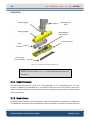
1
6205 BATHYMETRY AND SIDE SCAN SONAR USER HARDWARE MANUAL 0014877_REV_B EdgeTech 4 Little Brook Road West Wareham, MA 02576 Tel: (508) 291-0057 Fax: (508) 291-2491 www.EdgeTech.com ii The information, figures, and specifications in this manual are proprietary and are issued in strict confidence on condition that they not be copied, reprinted, or disclosed to a third party, either wholly or in part, without the prior, written consent of EdgeTech. Any reproduction of EdgeTech supplied software or file sharing is strictly prohibited. ©Copyright 2014 by EdgeTech. All rights reserved. Microsoft® and Windows® are registered trademarks of Microsoft Corporation. Storm Case™ is a trademark of Pelican. HYPACK® and HYSWEEP® are registered trademarks of Hypack, Inc. 6205 BATHYMETRY AND SIDE SCAN SONAR 0014877_REV_B iii WARNING – READ THIS FIRST! All personnel involved with the installation, operation, or maintenance of the equipment described in this manual should read and understand the warnings and recommendations provided below. Static Sensitive Devices This equipment contains devices that are extremely sensitive to static electrical charges. Therefore extreme care should be taken when handling them, as static electricity may be present on the body and clothing. Normal handling precautions involve the use of anti-static protection materials and grounding straps for personnel. RFI/EMI This equipment generates, uses, and can generates radio frequency energy. Therefore if the equipment is not installed properly, it may cause interference with radio communications. The equipment has not been tested for compliance with the appropriate FCC rules designed to provide reasonable protection against such interference when operated in a commercial environment. Therefore when operating the equipment in a residential area, the user may be required to take whatever measures are needed and incur any expenses necessary to eliminate interference; it is the user's responsibility to verify that the system complies with the applicable FCC emission limits. High Voltages High Voltage may be present in all parts of the system. Use caution when the electronics are removed from their containers for servicing. Improper Line Voltage Operation with improper line voltage may cause serious damage to the equipment. Always ensure that the proper line voltage is used. iv HARDWARE VARIATIONS AND COMPATIBILITY The 6205 Bathymetry and Side Scan Sonar system contains both standard PC components and proprietary hardware. At times EdgeTech may change the standard components due to their availability or performance improvements. Although the component manufacturers, along with their models and styles may change from unit to unit, replacement components will generally be interchangeable. EdgeTech will make every effort to see that replacement components are interchangeable and use the same software drivers. At times, however, direct replacements may not exist. When this happens, EdgeTech will provide the necessary drivers with the replacement part. EdgeTech may also change certain hardware per customer requirements. Therefore, portions of this manual, such as parts lists and test features, are subject to change. These sections should be used for reference only. When changes are made that affect system operation, they will be explicitly noted. Also, some options and features may not be active in the customer’s unit at time of delivery. Upgrades will be made available when these features are implemented. 6205 BATHYMETRY AND SIDE SCAN SONAR 0014877_REV_B v PREFACE We, the employees at EdgeTech, would like to thank you for purchasing a 6205 Bathymetry and Side Scan Sonar system. At EdgeTech, it is our policy to provide high quality, cost effective products and support services that meet or exceed your requirements. We also strive to deliver them on time and to continuously look for ways to improve them. We take pride in the products we manufacture and want you to be entirely satisfied with your equipment. Purpose of this Manual The purpose of this manual is to provide the user with information on the installation and use of EdgeTech’s 6205 Bathymetry and Side Scan Sonar system. For detailed information relating to software that came with this device, refer to the appropriate user software manual. Although this manual encompasses the latest operational features of the 6205 Bathymetry and Side Scan Sonar system, some features may be periodically upgraded. Therefore, the information in this manual is subject to change and should be used for reference only. Summary of Sections This manual is divided into the following sections and appendices: SECTION 1: Overview: Provides an introduction to the system. SECTION 2: System Description: Gives detailed specifications for the system. SECTION 3: Connections & Formats: Describes the connections and data formats. SECTION 4: Installation: How to set-up and install the system. SECTION 5: Principles of Operation: How to use the system. SECTION 6: FAQ: Frequently Asked Questions and answers. APPENDIX A: Backup & Restore: Describes the method for backing up and restoring the topside processor. APPENDIX B: Configuring the COM Ports: Explains how to configure the COM ports. APPENDIX C: Drawings & Diagrams: Contains large diagrams referenced in other sections. vi Warnings, Cautions, and Notes Where applicable, warnings, cautions, and notes are provided in this manual as follows: WARNING! Identifies a potential hazard that could cause personal injury or death to yourself or to others. CAUTION! Identifies a potential hazard that could be damaging to equipment or could result in the loss of data. NOTE: Recommendations or general information that is particular to the material being presented. It may also refer to another part of this manual or to another manual. Liability EdgeTech has made every effort to document the 6205 Bathymetry and Side Scan Sonar system in this manual accurately and completely. However, EdgeTech assumes no liability for errors or for any damages that result from the use of this manual or the equipment it documents. EdgeTech reserves the right to upgrade features of this system and to make changes to this manual without notice at any time. 6205 BATHYMETRY AND SIDE SCAN SONAR 0014877_REV_B vii WARRANTY STATEMENT All equipment manufactured by EdgeTech is warranted against defective components and workmanship for a period of one year after shipment. Warranty repair will be done by EdgeTech free of charge. Shipping costs are to be borne by the customer. Malfunction due to improper use is not covered in the warranty, and EdgeTech disclaims any liability for consequential damage resulting from defects in the performance of the equipment. No product is warranted as being fit for a particular purpose, and there is no warranty of merchantability. This warranty applies only if: i. The items are used solely under the operating conditions and in the manner recommended in Seller's instruction manual, specifications, or other literature. ii. The items have not been misused or abused in any manner, nor have repairs been attempted thereon without the approval of EdgeTech Customer Service. iii. Written notice of the failure within the warranty period is forwarded to Seller and the directions received for properly identifying items returned under warranty are followed. iv. The return notice authorizes Seller to examine and disassemble returned products to the extent Seller deems necessary to ascertain the cause for failure. The warranties expressed herein are exclusive. There are no other warranties, either expressed or implied, beyond those set forth herein, and Seller does not assume any other obligation or liability in connection with the sale or use of said products. Any product or service repaired under this warranty shall be warranted for the remaining portion of the original warranty period only. Equipment not manufactured by EdgeTech is supported only to the extent of the original manufacturer's warranties. viii SOFTWARE SERVICE OVERVIEW EdgeTech provides software services free of charge. The Software Service Agreement (SSA) does not address customer-specified modifications or enhancements. These services may be ordered separately. Furthermore, EdgeTech software upgrades are meant for the sole use of an EdgeTech customer. Any reproduction of EdgeTech supplied software or file sharing is strictly prohibited. Software Updates and Enhancements EdgeTech customers can download new software releases with all modifications and enhancements along with user's manual changes from the EdgeTech FTP site. Major software issues, should they occur, will be reported directly to the customer. New software releases consist of the following: Software enhancements that are not on the price list Software fixes and changes Product integration Documentation updates to on-line help Tests for compatibility with other modules Software patches consist of software that has undergone the following: Minor software enhancements Software fixes and changes Software Telephone, Facsimile, and E-mail Support The SSA entitles EdgeTech customers to contact EdgeTech Customer Service by telephone, facsimile, or email to report a difficulty, to discuss a problem or to receive advice on the best way to perform a task. When contacted, EdgeTech Customer Service will do the following: Respond within 24 hours Immediately attend to serious problems affecting operations Attempt to find an immediate work-around 6205 BATHYMETRY AND SIDE SCAN SONAR 0014877_REV_B ix RETURNED MATERIAL AUTHORIZATION Prior to returning any equipment to EdgeTech, a Returned Material Authorization (RMA) number must be obtained. The RMA will help us identify your equipment when it arrives at our receiving dock and track the equipment while it is at our facility. The material should be shipped to the address provided in the EdgeTech Customer Service section. Please refer to the RMA number on all documents and correspondences as well. All returned materials must be shipped prepaid. Freight collect shipments will not be accepted. EdgeTech will pay freight charges on materials going back to the customer after they have been evaluated and/or repaired. CAUTION! Never attempt to ship portable topside units in their Storm Case™ alone. Although rugged, these cases are not intended to be used as shipping containers, and the delicate internal components could be damaged if used in this manner. The following steps apply only to material being returned from outside the Continental United States. Follow them carefully to prevent delays and additional costs. 1. All shipments must be accompanied by three copies of your proforma invoice, showing the value of the material and the reason for its return. If the reason is for repair, it must be clearly stated in order to move through customs quickly and without duties being charged. Whenever possible, please send copies of original export shipping documents with the consignment. 2. If the value of the equipment is over $1000, the following Shipper's oath must be sent with the invoice. This oath can be typed on the invoice, or on a separate letterhead: "I, ______________________________, declare that the articles herein specified are the growth, produce, or manufacture of the United States; that they were exported from the United States from the port of _____________________, on or about _______________; that they are returned without having been advanced in value or improved in condition by any process of manufacture or any other means; and that no drawback, or allowance has been paid or admitted hereof. Signed ______________________________” 3. If there is more than one item per consignment, a packing list must accompany the shipment. It is acceptable to combine the proforma invoice and packing list as long as the contents of each carton are clearly numbered and identified on the invoice. x 4. Small items can be shipped prepaid directly to EdgeTech by FedEx, DHL, UPS, Airborne, etc. 5. If the equipment is the property of EdgeTech (formerly EG&G Marine Instruments Division), please insure for full value. 6. Fax one invoice, packing list, and a copy of the airway bill to EdgeTech upon shipment. 6205 BATHYMETRY AND SIDE SCAN SONAR 0014877_REV_B xi CUSTOMER SERVICE Customer service personnel at EdgeTech are always eager to hear from users of our products. Your feedback is welcome, and is a valuable source of information which we use to continually improve these products. Therefore, we encourage you to contact EdgeTech Customer Service to offer any suggestions or to request technical support: E-mail: [email protected] Mail: 4 Little Brook Road West Wareham, MA 02576 Telephone: (508) 291-0057 Facsimile: (508) 291-2491 24-Hour Emergency Technical Support Line: (508) 942-8043 For more information please go to www.EdgeTech.com. xii COMPANY BACKGROUND EdgeTech (formerly EG&G Marine Instruments) traces its history in underwater data acquisition and processing back to 1966. EdgeTech has designed, developed, and manufactured products, instruments, and systems for the acquisition of underwater data, including marine, estuarine, and coastal applications for over 45 years. The company has responded to the needs of the scientific, Naval and offshore communities by providing equipment, such as sub-bottom profilers, side scan sonar, acoustic releases, USBL positioning systems, and bathymetric systems that have become standards in the industry. EdgeTech has also consistently anticipated and responded to future needs through an active research and development program. Current efforts are focused on the application of cutting edge CHIRP and acoustic technology. 6205 BATHYMETRY AND SIDE SCAN SONAR 0014877_REV_B xiii TABLE OF CONTENTS WARNING – READ THIS FIRST! ........................................................................................................... iii Static Sensitive Devices ........................................................................................................................... iii RFI/EMI.................................................................................................................................................... iii High Voltages .......................................................................................................................................... iii Improper Line Voltage ............................................................................................................................ iii HARDWARE VARIATIONS AND COMPATIBILITY .................................................................................. iv PREFACE ............................................................................................................................................ v Purpose of this Manual ............................................................................................................................ v Summary of Sections................................................................................................................................ v Warnings, Cautions, and Notes............................................................................................................... vi Liability .................................................................................................................................................... vi WARRANTY STATEMENT .................................................................................................................. vii SOFTWARE SERVICE OVERVIEW....................................................................................................... viii Software Updates and Enhancements.................................................................................................. viii RETURNED MATERIAL AUTHORIZATION ............................................................................................ ix CUSTOMER SERVICE .......................................................................................................................... xi COMPANY BACKGROUND ................................................................................................................ xii TABLE OF CONTENTS ....................................................................................................................... xiii LIST OF FIGURES.............................................................................................................................. xvi LIST OF TABLES ............................................................................................................................. xviii SECTION 1: OVERVIEW ..................................................................................................................1-1 1.1 Supplied Components ................................................................................................................... 1-1 1.2 Optional Equipment ...................................................................................................................... 1-1 1.3 Software Description .................................................................................................................... 1-2 SECTION 2: SYSTEM DESCRIPTION..................................................................................................2-1 2.1 The 6205 Sonar Head .................................................................................................................... 2-1 2.1.1 Sonar Processor ...................................................................................................................... 2-2 2.1.2 Sonar Arrays ........................................................................................................................... 2-2 2.1.3 Sound Velocity Sensor ............................................................................................................ 2-3 xiv 2.1.4 Housing ................................................................................................................................... 2-3 2.1.5 Mounting Plate ....................................................................................................................... 2-3 2.2 Field Exchangeable Frequency Operations ................................................................................... 2-4 2.3 The 6205 Topside Interface ........................................................................................................ 2-10 2.3.1 6205-R Rack Mount Topside Interface ................................................................................. 2-10 2.3.1.1 Topside Computer’s Minimum Requirements............................................................... 2-11 2.3.2 6205-P Portable Topside Interface ....................................................................................... 2-12 2.4 Deck Cable................................................................................................................................... 2-13 2.5 Detailed Specifications................................................................................................................ 2-13 SECTION 3: CONNECTIONS & FORMATS .........................................................................................3-1 3.1 Data Formats................................................................................................................................. 3-1 3.2 System Connections and Data Flow.............................................................................................. 3-2 3.2.1 Ethernet LAN Connections ..................................................................................................... 3-2 3.2.2 Serial Port Connections .......................................................................................................... 3-2 3.2.3 Hardware Connectivity ........................................................................................................... 3-2 3.2.3.1 Serial Port Configuration Examples ................................................................................. 3-4 3.2.4 Sonar Data Flow ..................................................................................................................... 3-5 SECTION 4: INSTALLATION .............................................................................................................4-1 4.1 Unpacking and Inspecting ............................................................................................................. 4-1 4.2 Sonar Head Installation ................................................................................................................. 4-1 4.2.1 Over-the-Bow Deployment .................................................................................................... 4-1 4.2.2 Over-the-Side Deployment..................................................................................................... 4-2 4.3 Positioning the Topside Interface Box .......................................................................................... 4-3 4.4 Topside Connections ..................................................................................................................... 4-3 4.5 Care and Maintenance .................................................................................................................. 4-5 SECTION 5: PRINCIPLES OF OPERATION ..........................................................................................5-1 5.1 Confirming Supporting Data is Present......................................................................................... 5-1 5.2 DISCOVER Bathymetric ................................................................................................................. 5-3 5.3 Third Party Software ..................................................................................................................... 5-3 5.3.1 HYPACK ................................................................................................................................... 5-4 5.3.2 SonarWiz................................................................................................................................. 5-4 6205 BATHYMETRY AND SIDE SCAN SONAR 0014877_REV_B xv 5.3.3 QINSy ...................................................................................................................................... 5-4 5.3.4 CARIS ...................................................................................................................................... 5-4 SECTION 6: FAQ.............................................................................................................................6-1 APPENDIX A: BACKUP AND RESTORE.............................................................................................. A-1 A.1 Backing up the System Drive ....................................................................................................... A-1 A.2 Restoring the System Drive.......................................................................................................... A-1 APPENDIX B: CONFIGURING COM PORTS ....................................................................................... B-1 B.1 One Sensor ....................................................................................................................................B-1 B.2 Two Sensors ..................................................................................................................................B-9 B.3 Three Sensors..............................................................................................................................B-12 APPENDIX C: DRAWINGS & DIAGRAMS .......................................................................................... C-1 xvi LIST OF FIGURES Figure 2-1: 6205 Sonar Head Components ................................................................................................ 2-2 Figure 2-2: SVS in Nose of Sonar Head ...................................................................................................... 2-3 Figure 2-3: Mounting Plate ........................................................................................................................ 2-4 Figure 2-4: Unit on Stable Platform ........................................................................................................... 2-4 Figure 2-5: Removing the Cap Screws........................................................................................................ 2-5 Figure 2-6: Top Housing and Deck Cable Removed ................................................................................... 2-5 Figure 2-7: Array Cables Unplugged .......................................................................................................... 2-6 Figure 2-8: Cap Screws Removed............................................................................................................... 2-6 Figure 2-9: Port Array Removed ................................................................................................................ 2-7 Figure 2-10: Cable in Keyway ..................................................................................................................... 2-7 Figure 2-11: Inserting New Array ............................................................................................................... 2-8 Figure 2-12: Array Flush with Housing ....................................................................................................... 2-8 Figure 2-13: Array Secured in Place ........................................................................................................... 2-9 Figure 2-14: Array Replacement Complete................................................................................................ 2-9 Figure 2-15: Rack Mount Topside Rear Panel Diagram (Top) and Real Time Connections (Bottom) ...... 2-11 Figure 2-16: 6205-P Portable Topside...................................................................................................... 2-12 Figure 3-1: 6205-R Rack Mount Topside Interface Connections ............................................................... 3-3 Figure 3-2: Sonar Data Flow ....................................................................................................................... 3-5 Figure 4-1: 6205 Deployment, Option 1 – Over-the-Bow .......................................................................... 4-2 Figure 4-2: 6205 Deployment, Option 2 – Over-the-Side .......................................................................... 4-3 Figure 5-1: Sonar 192.9.0.101 Remote Desktop Connection Window ...................................................... 5-1 Figure 5-2: Serial Port Information Window .............................................................................................. 5-2 Figure 5-3: System Status Window ............................................................................................................ 5-3 Figure B-1: Sonar Remote Desktop Application, Main Screen .................................................................. B-2 Figure B-2: Sonar Remote Desktop, Shortcut to EdgeTech Folder ............................................................B-3 6205 BATHYMETRY AND SIDE SCAN SONAR 0014877_REV_B xvii Figure B-3: Finding the SonarSerial.ini File ................................................................................................B-4 Figure B-4: SonarSerial.ini File ...................................................................................................................B-5 Figure B-5: Diagnostic Window, Reporting Ports Inactive Error ................................................................B-5 Figure B-6: Rebooting Sonar from the Main Screen ..................................................................................B-6 Figure B-7: Checking Serial Port Information.............................................................................................B-7 Figure B-8: Checking Sensor Status............................................................................................................B-8 Figure B-9: Closing the System Status Window .........................................................................................B-9 Figure B-10: SonarSerial.ini File ...............................................................................................................B-10 Figure B-11: Checking Sensors’ Usages ....................................................................................................B-11 Figure B-12: All Sensors Set .....................................................................................................................B-13 Figure B-13: Checking all COM Ports .......................................................................................................B-15 Figure C-1: 6205 Sonar Head Drawing – A ................................................................................................. C-2 Figure C-2: 6205 Sonar Head Drawing – B ................................................................................................. C-3 Figure C-3: 6205 Sonar Head Drawing – C ................................................................................................. C-4 Figure C-4: 6205 Sonar Head Drawing – D ................................................................................................. C-5 Figure: C-5: 6205 Wiring Diagram .............................................................................................................. C-6 Figure C-6: 6205-P Portable Topside Interface Box ................................................................................... C-7 Figure C-7: Array Color Codes .................................................................................................................... C-8 xviii LIST OF TABLES Table 2-1: 6205 Specification ................................................................................................................... 2-14 6205 BATHYMETRY AND SIDE SCAN SONAR 0014877_REV_B 1-1 SECTION 1: OVERVIEW EdgeTech’s 6205 is a combined, fully-integrated, swath bathymetry and dual frequency side scan sonar system. The 6205 uses multiple receive element transducers, and one discrete transmit element to produce real-time, high-resolution, 3D maps of the seafloor, while also providing co-registered simultaneous, dual frequency side scan and bathymetric data. The high number of channels enables superb rejection of multi-path effects, reverberation, and acoustic noise. The 6205 provides bathymetry and dual frequency side scan, operating at 230/520 kHz or 520/1600 kHz. Bathymetry data are obtained on either the 230 kHz or the 520 kHz frequency, while the Side Scan imagery is collected simultaneously on both frequencies. The sonar electronics and arrays are mounted onto a streamline body that is deployed over-the-bow or side of a survey vessel. Sonar data is transferred from the transceiver to the processing unit on board via an Ethernet network interface. Default configuration for the 6205 includes an integrated sound velocity sensor. The system can interface with standard DGPS/RTK systems, MRUs, SVPs, CTDs, Altimeters, and Gyros, altogether offering a powerful and versatile acquisition system that is suitable for many different applications. 1.1 Supplied Components The following components come standard with the 6205 system: 6205 Swath Bathymetry and Side Scan Sonar System with 20 m (65 ft) Deck Cable (please refer to the Cable Drawing APPENDIX C: DRAWINGS & DIAGRAMS). Sound Velocity Sensor (SVS, located in the Sonar Head) Large Pelican Hardigg Shipping Case 6205-R 19-inch Rack Mount Interface Box EdgeTech’s DISCOVER Bathymetric Acquisition Software Electronic Copy of the Manuals NOTE: The customer is to provide cable path between the 6205 Topside Processor Unit and the Sonar Head. 1.2 Optional Equipment Arrays for field exchangeable frequency operations 6205-P Portable Topside with Ruggedized Laptop preloaded with EdgeTech’s DISCOVER Bathymetric Acquisition Software 1-2 SECTION 1: OVERVIEW Topside Restore Software Spares Kit 1.3 Software Description EdgeTech’s DISCOVER Bathymetric Software Acquisition package provides a way to control, store, and display the bathymetry and dual frequency side scan sonar data. The data are presented on a color waterfall display and are stored in JSF formats on the hard disk of the Topside Processor. (See sub-section 5.2: DISCOVER Bathymetric) 6205 BATHYMETRY AND SIDE SCAN SONAR 0014877_REV_B 2-1 SECTION 2: SYSTEM DESCRIPTION The complete 6205 system consists of a Swath Bathymetry and Side Scan Sonar Head and a Topside Interface Box. This section describes the main components that make up the 6205 system and lists its specifications. 2.1 The 6205 Sonar Head The 6205 Swath Bathymetry and Side Scan Sonar Head is available in a variety of frequency options: 230 kHz and 550 kHz with bathymetry on 230 kHz, 230 kHz and 550 kHz with bathymetry on 550 kHz and 550 kHz and 1600 kHz with bathymetry on 550 kHz. The frequency sets listed above were chosen to provide optimum results for any given water depth up to 200m below the transducer. The 230 kHz/550 kHz system with 230 kHz bathymetry was designed for water depths between 5m – 200m while the 550 kHz/1600 kHz for water depths between 0.5m – 50m. The optimal frequency option depends on the survey requirements. To try and mitigate the frequency tradeoffs, EdgeTech has designed the 6205 Sonar Head with field exchangeable arrays such that the bathymetry frequency can be switched from the low frequency channel to high frequency channel or vice versa. However, this feature only exists on the 230 kHz/550 kHz models. Also, the 6205 Swath Bathymetry and Side Scan Sonar Head comes standard with a Sonar Processor, Port and Starboard Sonar Arrays, a Sound Velocity Sensor (SVS), Housing (upper & lower), and a Mounting Plate. These components are demonstrated in Figure 2-1. 2-2 Error! Reference source not found.SYSTEM DESCRIPTION Mounting Pole (CFE) Mounting Plate Housing (Upper) Sound Velocity Sensor (SVS) Housing (Lower) Sonar Processor Sonar Arrays (Port and Stbd) Figure 2-1: 6205 Sonar Head Components NOTE: The terms used in Figure 2-1 will be referenced throughout the document. 2.1.1 Sonar Processor The 6205 Sonar Processor has a built in PC running Windows XP as its operating system. The main firmware installed on the embedded PC is an application called sonar.exe. This firmware controls the sonar’s hardware and performs specific functions such as the signal processing and time synchronization of the acquired data. 2.1.2 Sonar Arrays The 6205 provides bathymetry and dual frequency side scan simultaneously, and operates at 230/520 kHz or 520/1600 kHz. Bathymetry data are obtained on either the 230 kHz or the 520 kHz channel, while the 6205 BATHYMETRY AND SIDE SCAN SONAR 0014877_REV_B 2-3 Side Scan imagery is collected simultaneously on both frequency channels. The 6205 utilizes two arrays (port and starboard) to map the seafloor, much like a dual head multibeam system. Each 6205 array is constructed using 11 independent longitudinal PZT elements. One of these is used for the transmit function and as a full resolution side scan receiver, while the remaining 10 elements make up an approximately half wavelength spaced array of sensors for its bathymetry receiver. 2.1.3 Sound Velocity Sensor The 6205 Sonar Head has a flooded section that is used to house an AML sound velocity sensor (SVS) providing a response time of 47 μs, a resolution of 0.001 m/s, and a theoretical accuracy of ±0.025 m/s. A closer look at the SVS is presented in Figure 2-2. SVS Figure 2-2: SVS in Nose of Sonar Head 2.1.4 Housing The 6205 housing is made from Fiber Reinforced Polymer (FRP) Composite and stainless steel and has an upper and lower section. The housing supplies a streamline body for efficient underwater maneuvers rated up to 12 knots and protects the SVS, arrays, and deck cable connections. 2.1.5 Mounting Plate The 6205 mounting plate is made of stainless steel and has been designed with a variable bolt pattern to secure the system to several different deployment mechanisms, thereby cutting back on installation and mobilization time. 2-4 Error! Reference source not found.SYSTEM DESCRIPTION Figure 2-3: Mounting Plate 2.2 Field Exchangeable Frequency Operations In order to switch between the different bathymetry frequencies the 6205 arrays must be exchanged with the corresponding bathymetry array. For instance, if the sonar head is currently a 230 kHz/550 kHz Side Scan with 230 kHz bathymetry and it is desired to exchange the bathymetry frequency to the 550 kHz channel, then the following procedure should be followed. The only tool needed for this operation is a 3 /16 inch Allen Wrench. 1. Place the unit on a stable and level platform, such as a work bench or boat deck. 6205 BATHYMETRY AND SIDE SCAN SONAR 0014877_REV_B 2-5 Figure 2-4: Unit on Stable Platform 2. Take off the top half of the housing by removing the fourteen 1/4” – 20 x 5/8” cap screws using a 3 /16” Allen key. Figure 2-5: Removing the Cap Screws 3. Unplug the deck cable (green) from the bottle, remove it from the top housing, and set the top housing aside. 2-6 Error! Reference source not found.SYSTEM DESCRIPTION Figure 2-6: Top Housing and Deck Cable Removed 4. Unplug the port and starboard array cables (yellow and black cables) from the bottle. Figure 2-7: Array Cables Unplugged 6205 BATHYMETRY AND SIDE SCAN SONAR 0014877_REV_B 2-7 5. Tilt the lower housing onto its starboard side and remove all six 1/4” – 20 x 1.5” cap screws using the same 3/16 Allen key. Figure 2-8: Cap Screws Removed 6. Remove the port array from the lower housing by pushing on the fore section of the array so that it is titled away at an angle from the housing. Figure 2-9: Port Array Removed 2-8 Error! Reference source not found.SYSTEM DESCRIPTION 7. Then push on the aft section of the array and pull forward so that the cables come through the keyway and removing the entire array from the housing. Figure 2-10: Cable in Keyway 8. Take the new array and thread it through the keyway, pushing the aft end into the groove. 6205 BATHYMETRY AND SIDE SCAN SONAR 0014877_REV_B 2-9 Figure 2-11: Inserting New Array 9. Then push back and tilt the array into place until the array face is flush with the housing. Figure 2-12: Array Flush with Housing 10. Secure in place using the six 1/4” – 20 x 1.5” cap screws and the 3/16” Allen key. 2-10 Error! Reference source not found.SYSTEM DESCRIPTION Figure 2-13: Array Secured in Place 11. Tilt housing on its port side and repeat steps 5 – 10 to replace the starboard array with the alternate one. 12. Connect the array cables to the bottle making sure the correct pins match up. 13. Thread the deck cable through the hole in the top housing and reconnect it to the bottle. 14. Replace the top housing, ensuring the deck cable is in the aft position of the sonar head, and securing it with the fourteen 1/4” – 20 x 5/8” cap screws and 3/16” Allen key. 6205 BATHYMETRY AND SIDE SCAN SONAR 0014877_REV_B 2-11 Figure 2-14: Array Replacement Complete 2.3 The 6205 Topside Interface The 6205 Topside Interface has two purposes: To provide power to the Sonar Head AND To provide a direct link between the Sonar Head, any supporting sensors, and the Topside Computer. The sonar interface box delivers power to the system and transmits/receives data via the provided 10 m (32 ft) Deck Cable and a SubConn 16 pin wet mate connector. The topside sonar interface box also supplies three COM ports and/or one Ethernet port to intake the navigation, heading, and attitude data from the supporting sensors. The first two RS232 serial ports are configured for high speed and high accuracy (10Mbps), while the third RS232 serial port is configured for standard serial connections. Typical latencies for the high speed/high accuracy ports are less than 100us, whereas the standard serial port and Ethernet may have up to 100ms. This topside interface box comes in two forms: Rack mountable topside interface box for use with a customer-supplied computer, OR Portable splash proof interface box that includes a ruggedized laptop. These two options are defined in the following sections. 2-12 Error! Reference source not found.SYSTEM DESCRIPTION 2.3.1 6205-R Rack Mount Topside Interface The 6205-R Rack Mount Topside Interface box has been designed to slide into a 19-in Rack Mount Optima Case. It provides the user with a dry connection to the sonar head for all the supporting sensors (i.e. GPS, MRU, etc.). It also provides three input/output serial ports, four Ethernet ports, AC power input, on/off switch, and two BNC connectors that supply an input trigger and 1PPS sync. These interfaces are illustrated in Figure 2-15. Figure 2-15: Rack Mount Topside Rear Panel Diagram (Top) and Real Time Connections (Bottom) The Rack Mount option does not come with a topside computer and must be supplied by the customer (minimum requirements are provided in sub-section 2.3.1.1). EdgeTech’s DISCOVER Bathymetric 6205 BATHYMETRY AND SIDE SCAN SONAR 0014877_REV_B 2-13 Acquisition Software is included on a DVD that is supplied upon delivery of the 6205 Sonar Head. This software can also be downloaded from the EdgeTech FTP site. Please contact EdgeTech Customer Service for FTP site credentials. 2.3.1.1 Topside Computer’s Minimum Requirements If the topside computer is to be supplied by the customer then it must have the following minimum requirements: Windows 7 Professional Operating System Intel Core i7-4900MQ @ 2.8GHz Processor or similar 8 GB of Memory (RAM) 500GB Hard Drive 4 USB Ports 1 Ethernet Port 1 VGA Port 2.3.2 6205-P Portable Topside Interface The 6205-P Portable Topside Interface is a portable and splash proof design of the 6205-R Rack Mount Interface box. It offers all the same connections to the 6205 Sonar Head for the supporting sensors (i.e. GPS, MRU, etc.) and does so with a series of break out cables. See Figure 2-16 for a picture of the portable option. Figure 2-16: 6205-P Portable Topside 2-14 Error! Reference source not found.SYSTEM DESCRIPTION This option comes standard with a ruggedized laptop, preloaded with EdgeTech’s DISCOVER Bathymetric Acquisition Software. The ruggedized laptop is a high performance PC, running Windows 7 Professional as its operating system. It also has a Quad Core processor and comes with a 500 GB hard drive. This laptop is used to simultaneously execute EdgeTech’s DISCOVER Bathymetric Acquisition Software, as well as any third party data acquisition and post processing software. NOTE: Even though the Topside Computer may look and operate like a general purpose PC, it is not designed to have other software installed. Installing other software besides the ones supplied with the system can have undesirable effects, such as poor and/or slow performance when acquiring bathymetry and dual frequency side scan data. 2.4 Deck Cable The deck cable is a 20 meter (65 feet) underwater, high speed network data and power cable. The deck cable includes Cat 5e 4 pair stranded conductors that meets or exceeds TIA 568-B and is suitable for 10Base-T and 100Base-T. The deck cable is also terminated with a Subconn 16 pin wet mate connector on both ends, has a breaking strength of 545 kg (1200 lbs), and provides power and telemetry to the 6205 Sonar Head. NOTE: This deck cable is not to be used for towing. 2.5 Detailed Specifications Detailed specifications for the 6205 system can be found in Table 2-1. MODEL 300/600/300 KHZ 600/1600/600 KHZ 76.2 L x 21.1 W x 15.0 H cm 30 L x 8.3 W x 11 H in 19.9 kg (43.8 lbs) 76.2 L x 21.1 W x 15.0 H cm 30 L x 8.3 W x 11 H in 19.9 kg (43.8 lbs) PHYSICALS Size Weight 6205 BATHYMETRY AND SIDE SCAN SONAR 0014877_REV_B 2-15 MODEL 300/600/300 KHZ 600/1600/600 KHZ Construction FRP Composite / Stainless Steel Reinforced Blue Angels Yellow FRP Composite / Stainless Steel Reinforced Blue Angels Yellow O-Ring Seal with Purge Valve O-Ring Seal with Purge Valve Center Frequency 230/520 kHz 520/1610 kHz Range (per Side) 225/125 m (738/410 ft) 125/35m (410/115 ft) Range Resolution 30/10 mm (1.18/0.4 in) 10/6 mm (0.4/0.2 in) Beam Width Along Track 0.64°/0.5° (2-way) 0.5°/0.2° (2-way) Depression 30° 30° Color Sealing SIDE SCAN SONAR INTERFEROMETRIC SWATH BATHYMETRY Center Frequency 230 kHz 520 kHz Maximum Swath 350 m (1148 ft) 150 m (492 ft) Range Resolution 60 mm (2.36 in) 30 mm (2.36 in) Ping Repetition Rate (Both Sides Simultaneously) 5 m (16 ft) = 130 Hz 25 m (82 ft) = 30 Hz, 50 m (164 ft) =15Hz, 100 m (328 ft) = 8 Hz 200 m (656 ft) 5 m (16 ft) = 130 Hz 25 m (82 ft) = 30 Hz, 50 m (164 ft) = 15 Hz, 100 m (328 ft) = 8 Hz 75 m (246 ft) Max Depth Below Tx SONAR HEAD POWER REQUIREMENTS DC Input 48 VDC 48 VDC Power 100 Watts 100 Watts Operating Temperature 0°C to 40°C (32°F to 104°F) 0°C to 40°C (32°F to 104°F) Storage Temperature -20°C to 60°C (-4°F to 140°F) -20°C to 60°C (-4°F to 140°F) Relative Humidity Operating 0 to 80%, Non-Operating 0 to 100% Operating 0 to 80%, Non-Operating 0 to 100% ENVIRONMENT TOPSIDE INTERFACE 2-16 Error! Reference source not found.SYSTEM DESCRIPTION MODEL 300/600/300 KHZ 600/1600/600 KHZ Interface 100 baseT Ethernet Serial RS-232 110/220 VAC Auto-Sensing 100 baseT Ethernet Serial RS-232 110/220 VAC Auto-Sensing Power Supply Table 2-1: 6205 Specification 6205 BATHYMETRY AND SIDE SCAN SONAR 0014877_REV_B 3-1 SECTION 3: CONNECTIONS & FORMATS Being a highly-advanced computerized device, the 6205 system relies on specific data formats and connections to produce its high quality images. This section describes these data formats and connections, along with providing diagrams to help the user better understand the hardware and data flow within the system. 3.1 Data Formats In order to collect valid survey data, the following is required to support the survey operations and correct processing of the 6205 Bathymetry and Dual Frequency Side Scan echo data: a. b. c. d. GPS Position in NMEA format, latitude and longitude Heading data in NMEA format or EM1000 binary format Attitude or Roll, Pitch and Heave data in TSS1 or EM1000 binary format Time sync data in NMEA format These data may be supplied by 1, 2, or 3 individual sources and are listed below in order of priority. a. Position Data – this may be supplied via any of the following NMEA type sentences/messages: i. $xxGGA ii. $xxGLL iii. $xxRMC iv. $xxGGK ** (Applanix PosMV Format) v. $PTNL, GGK, … ** (Trimble Format) ** = Non-NMEA standard sentences b. Heading Data – this maybe input via: i. NMEA, $xxHDT sentence, or ii. EM1000 binary format along with attitude data c. Attitude (Roll, Pitch, and Heave) Data – this may be input via: i. TSS1 format, or ii. EM1000 binary format d. Time Input - supported sentences are in order of priority/use i. $xxZDA ii. $xxRMC iii. $xxGGA iv. $xxGLL v. $xxGGK (derived from data in item a. above) 3-2 SECTION 3: CONNECTIONS & FORMATS 3.2 System Connections and Data Flow The following sub-sections describe the connections and data flow for the 6205 system. 3.2.1 Ethernet LAN Connections The Ethernet LAN connection from the Sonar Head to the 6205 Topside Interface is made using a physical wired connection via the standard 10 m deck cable. This cable is fixed to the Sonar Head and provides a direct connection from the Sonar Head to the 6205 Sonar Interface box. The 6205 Sonar Interface then connects to a Topside Computer via a standard RJ-45 Ethernet plug. The correct IP addresses for the sonar head and topside PC are listed below. Sonar Head IP Address = 192.9.0.101 Topside PC IP Address = 192.9.0.99 NOTE: The factory defaults for the 6205 sonar head IP address is 192.9.0.101 and should not be changed for any reason. The ruggedized laptop that is supplied with the 6205-P portable topside interface will also be preconfigured to 192.9.0.99 on delivery from the factory. It is only when the customer has to supply their own topside computer, the IP address needs to be set to the address above. 3.2.2 Serial Port Connections There are three RS-232 serial ports provided on the 6205 Sonar Interface box. COM1 and COM2 have been configured for high speed and high accuracy (10Mbps). COM3 is configured for standard RS-232 serial connections. Typical latencies for the high speed/high accuracy ports are less than 100us, whereas the standard serial port has up to 100ms. These serial ports are provided to intake the navigation, heading, and attitude (roll, pitch, and heave) data from the supporting sensors. Please see APPENDIX B: CONFIGURING COM PORTS on how to configure the COM ports. 3.2.3 Hardware Connectivity Figure 3-1 is a block diagram that illustrates the interconnections between the 6205 Swath Bathymetry and Dual Frequency Side Scan Sonar Head, the 6205-R Rack Mount Topside Interface, and all supporting 6205 BATHYMETRY AND SIDE SCAN SONAR 0014877_REV_B 3-3 sensors. This illustration also gives three examples of possible sensor configurations which are explained below. Topside Computer IP Address 192.9.0.99 Example 1 Example 2 Attitude, Heading, Position, Time Not Used Attitude Not Used Example 3 Attitude Heading, Position, Time Not Used Heading Position, Time Power 115/220 VAC 6205 Sonar Head IP Address: 192.9.0.101 Figure 3-1: 6205-R Rack Mount Topside Interface Connections The 6205-P Portable Topside Interface connections are similar and are presented in APPENDIX C: DRAWINGS & DIAGRAMS. In Figure 3-1, the 6205 Sonar Interface connects to the Sonar Head via the Deck Cable. Navigation, heading, roll, pitch, and heave data from the supporting sensors via COM ports 1, 2, and/or 3, are inputted at the Sonar Interface, passed through the Deck Cable, and logged by the Sonar Processor in the Sonar Head. These data are transmitted, along with the raw side scan data, with a common timestamp up the deck cable to the 6205 Sonar Interface, and are passed to the Topside Computer through the Deck Cable and via Ethernet Port 1 (IP Address: 192.9.0.99). 3-4 SECTION 3: CONNECTIONS & FORMATS The Topside Computer then processes these data using the DISCOVER Bathymetric software to send amplitude, angle and range data to the 3rd party software for logging and post processing. This process is explained in further details in the following section. The 3rd party software and DISCOVER Bathymetric processors may all run on the same computer. 3.2.3.1 Serial Port Configuration Examples The first example in Figure 3-1 depicts a sensor interfacing to the 6205 Sonar Interface that provides time, navigation (latitude/longitude), heading, roll, pitch, and heave data over one serial connection, such as a NovaTel ProPak 6 or Applanix PosMV. As depicted by Figure 3-1, the sensor is connected to COM1. The second example shows the most common interfacing scenario, a GPS that provides navigation and heading data, accompanied by a motion sensor for attitude measurements. The COM ports should be assigned as such: COM1 = MRU (Roll, Pitch, Heave) COM2 = GPS (Navigation and Heading) These assignments may be interchanged between COM1 and COM2 because both ports have been configured for high speed and high accuracy. COM3 should not be used in this scenario. The third and last example portrays the situation where the GPS does not provide heading data. In this case, three sensors are required – a GPS for navigation (latitude/longitude), a Gyro for heading, and a motion sensor for roll, pitch, and heave measurements. Therefore, all three COM ports should be used and assigned as follows: COM1 = MRU (Roll, Pitch, Heave) COM2 = Gyro (Heading) COM3 = GPS (latitude/longitude) The sensors allocated to COM1 and COM2 may be interchanged because of the same reason stated above in the second example. The GPS data, or latitude and longitude data, must be allotted to COM3, because position can tolerate a 100ms latency, whereas attitude and heading are crucial to correcting the wide swath of data. NOTE: To configure the serial ports according to the examples given above, please see APPENDIX B: CONFIGURING COM PORTS. 6205 BATHYMETRY AND SIDE SCAN SONAR 0014877_REV_B 3-5 3.2.4 Sonar Data Flow DISCOVER Bathymetric software acquisition package provides a way to control, store, and display the bathymetry and side scan sonar data. DISCOVER Bathymetric contains two processors: one to process the bathymetry solutions, called the Bathymetric Processor, and the second to process and display the dual frequency side scan data. To illustrate the data flow between DISCOVER, the Bathymetric Processor, and any third party software, the block diagram in Figure 3-2 is used. NOTE: The 6205 Sonar Interface Box in the flow chart below can be either the 6205-R Rack Mount Interface Box or the 6205-P Portable Interface Box. Time, Heading, Position, and Motion Data [1] 6205 Sonar Interface Box [2] Auxiliary Data Sent to Sonar Head 6205 Sonar Head [3] Auxiliary Data Gets Time Stamped, Packaged with SV, and Sent Back to Interface Box. [4] DISCOVER Bathymetric Raw Sonar Data SV [7] Third Party Software [6] Range/Angle Data + Auxiliary Data + Dual Frequency SS Data Range/Angle Data [8] Third Party Files [5] Bathymetric Processor Figure 3-2: Sonar Data Flow 3-6 SECTION 3: CONNECTIONS & FORMATS The flow chart in Figure 3-2 demonstrates the following: 1. The auxiliary sensors provide time, heading, position (latitude/longitude), and motion (roll, pitch, and heave) data to the 6205 Sonar Interface Box via the provided RS-232 serial ports. 2. These auxiliary data are then relayed to the 6205 Sonar Head via the Deck Cable. 3. Here, the auxiliary data are combined with the raw sonar data and instantaneous sound velocity (SV) measurements, where it is time stamped with a common value and sent back to the 6205 Sonar Interface. 4. DISCOVER Bathymetric Acquisition Software intakes the raw sonar data and sends it to the Bathymetric Processor. 5. The Bathymetric Processor processes the raw sonar data to produce uncorrected range and angle data and transmits this back to DISCOVER Bathymetric where it is packaged with the auxiliary and dual frequency side scan data. At this point each ping is represented by a complete data package containing all sonar and auxiliary data. NOTE: Once the data is passed back to DISCOVER Bathymetric, these data are shown on the provided graphical displays to show the bathymetry and simultaneous dual frequency side scan data in real time. These data may also be recorded as a *.JSF file if the user desires. 6. This complete data package (range/angle, dual frequency side scan, and all auxiliary data) is sent to the third party software. 7. The third party software then logs these complete data packets to their native format. The third party also provides graphical displays to show the bathymetry, dual frequency side scan, and auxiliary data. 8. Finally, these three-dimensional third party data files contain every piece of information to post process the data and generate hydrographic final products. 6205 BATHYMETRY AND SIDE SCAN SONAR 0014877_REV_B 4-1 SECTION 4: INSTALLATION Installing the 6205 system begins with unpacking and inspecting it after shipping, installing the sonar head, in the desired configuration, and then connecting all the components. This section provides an overview for unpacking, inspecting, installing, and caring for the EdgeTech 6205 Swath Bathymetry and Dual Frequency Side Scan Sonar System. 4.1 Unpacking and Inspecting The Sonar Head, Deck Cable, Transducers, Pole Mount Flange, Interface box with cables, Laptop with transformer and CDs are all shipped in a single, reusable, heavy duty transport case. All documentation, including the manuals, is provided in electronic form on the CDs. Before unpacking the system’s components, inspect the shipping containers for any damage. If any damage is noticed, please report it to the carrier and to EdgeTech immediately. If the shipping containers appear damage free, carefully unpack the components and inspect them. Also, pleases check the packing list and verify that all the items on the list are included. Again, if any damage is found, please report it to the carrier and to EdgeTech immediately. If any items are missing, please contact EdgeTech Customer Service. Do not install or operate any equipment that appears to be damaged. Although the items shipped may vary, depending on the customer’s requirements, the standard components for the 6205 Swath Bathymetry and Dual Frequency Side Scan Sonar system are listed in SECTION 1: OVERVIEW. 4.2 Sonar Head Installation The 6205 System’s installation on the survey vessel is the customer’s responsibility, and certain considerations need to be kept in mind. The Sonar Head can be mounted on the side of a vessel, but it is recommended to secure the 6205 to the bow of the boat. Consideration must be given to keel clearance for the former. 4.2.1 Over-the-Bow Deployment The first, and recommended option, is to mount the 6205 Sonar Head to the bow of the survey vessel. An example of an over-the-bow deployment is depicted in the photographs in Figure 4-1. If help is needed with this type of installation, please do not hesitate to contact EdgeTech Customer Service. 4-2 SECTION 4: INSTALLATION Figure 4-1: 6205 Deployment, Option 1 – Over-the-Bow 4.2.2 Over-the-Side Deployment An alternative to the bow mount is to secure the 6205 Sonar Head over the side of the survey vessel via a pole. An example of an over-the-side deployment is illustrated in the images in Figure 4-1. If help is needed with this type of installation, please contact EdgeTech Customer Service. 6205 BATHYMETRY AND SIDE SCAN SONAR 0014877_REV_B 4-3 Figure 4-2: 6205 Deployment, Option 2 – Over-the-Side 4.3 Positioning the Topside Interface Box The Topside Interface Box can be set up several ways, depending on which model was purchased. The 6205-R 19-in Rack Mount version should be located and set up in a dry, sheltered area on the survey vessel that is protected from weather and water spray. The 6205-P portable design is a bit more versatile since it is watertight when closed (but cannot ever be submerged), and can be set up anywhere on the survey vessel that is most convenient. Care should be taken however, to keep the ends of the breakout cables dry. Avoid areas of direct sunlight, especially in tropical environments, as heat build-up can occur and viewing status indicators can become difficult. The temperature should also consistently be between 0°C and 40°C (32°F and 104°F). Furthermore, the location should enable direct communications with the deck crew that is operating the survey vessel, Sonar Head, and other supporting sensors. 4.4 Topside Connections After the Sonar Head has been installed, and the Topside Interface Box correctly placed on the survey vessel, the supporting sensors can now be connected. To connect the supporting sensors, Sonar Head and Topside Interface Box: 4-4 SECTION 4: INSTALLATION 1. Setup the MRU as described in the MRU’s user manual. 2. Position and secure a MRU to the vessel’s center of motion. If the MRU cannot be mounted in this location, then please try to mount it as close as possible to the center of motion. 3. Setup the GPS as described in the GPS’s user manual. 4. Position and secure the GPS Antennas so that they have a clear view of the sky. Also ensure to secure the GPS receiver in a dry, sheltered area on the survey vessel that is protected from weather and water spray. 5. Ensure the sonar head is installed properly on the pole mount (whether it is at the bow or side of the vessel). 6. Measure the relative location of the MRU to the vessel’s center of motion. If the MRU was mounted exactly at the vessel’s center of motion, these measurements would be recorded as (0,0,0). 7. Measure the location of the GPS relative to the vessel’s center of motion. Typically, the primary antenna is used as the source of position. In this case, use the location of the primary antenna to measure the installation offset for the GPS. NOTE: These measurements are important and will be used later as installation offsets in the third party software. Please make sure to measure and note the exact location of the sensors to the vessel’s center of motion. Also, please remember the Z dimension is referenced to the water line. 8. Measure the location of the sonar head’s port and starboard arrays relative to the vessel’s center of motion. Since the system is treated similar to a dual headed multibeam echo sounder, each array will have a different measurement in the port/stbd direction but will be the same in the fore/aft and z directions. The location of each array’s acoustic center is provided in the Sonar Head drawing in APPENDIX C: DRAWINGS & DIAGRAMS. 9. Provide power to the 6205 Interface Box via the provided power cable. 10. Connect the Sonar Head to the 6205 Topside Interface box via the Subconn 16 pin connector. 11. Connect the MRU to COM1 and the Dual Head GPS to COM2 (or vice versa). a. A MRU is used to measure the pitch, roll, and heave of the survey vessel. b. A dual head GPS is used to gather heading and position (latitude/longitude) data. 6205 BATHYMETRY AND SIDE SCAN SONAR 0014877_REV_B 4-5 NOTE: If the GPS does not supply heading (i.e. single head only), then a Gyro (or other source of heading) must be used. In the case where another sensor is needed to provide heading, the sensors should be connected as COM1 – MRU, COM2 – Heading, COM 3 – GPS. The low latency ports (COM1 and COM2) must be designated to the low latency sensor information (i.e. attitude and heading). NOTE: Please refer to sub-section 3.2.2 for more information on connecting the COM Ports. Also, please use APPENDIX B: CONFIGURING COM PORTS to configure the COM ports for the individual sensors. 12. Connect the 6205 Interface box to the topside computer using an Ethernet cable. 13. Turn the PC on and launch DISCOVER Bathymetric Software. 14. If desired, launch any one of the supported third party software packages (i.e. Hypack, SonarWiz, or QINSy), setup the 6205 drivers, and input the installation offsets measured in steps 6 through 8. At this point, all equipment and software is ready for surveying. See SECTION 5: PRINCIPLES OF OPERATION for use of the system. 4.5 Care and Maintenance The 6205 Sonar Head is not designed for long term deployments and it is not recommended to keep the system in water for more than two weeks. After each mission, the system should be rinsed thoroughly with freshwater, making sure to rinse the SVS at the front and connectors at the back using the carry slots located on the sonar housing. The faces of the arrays should also be inspected after every deployment for organism growth or damage. If any residue is noticed, clean the array faces using a wash cloth with mild soap and water. If any damage is observed, contact EdgeTech Customer Service immediately. NOTE: Caution should be taken to ensure the 6205 Sonar Head is never turned on and run in air. Damage to the transducers can occur. 5-1 SECTION 5: PRINCIPLES OF OPERATION This section describes how to operate the 6205 system in order to collect data with DISCOVER Bathymetric and a third party topside interface. 5.1 Confirming Supporting Data is Present To ensure the Sonar Head’s processing unit is communicating properly with the Topside Processor, follow these steps. This section assumes all auxiliary sensors have been connected to the 6205 Interface Box (whether this be the 6205-R or 6205-P), the Sonar Head is installed on the survey vessel and is submerged in seawater. 1. On the Desktop, launch Remote Desktop to Sonar. The following window should appear: Figure 5-1: Sonar 192.9.0.101 Remote Desktop Connection Window 2. Click on Menu > Misc > Serial Port Information. 3. Check each COM port in the drop down menu to ensure the correct baud rates are set and data is coming through for each device and in the correct format (Figure 5-2). a. COM1 = MRU b. COM2 = GPS c. COM4 = Sound Velocity Sensor located in the Sonar Head’s housing NOTE: The GPS and MRU are interchangeable on COM1 and COM2 as long as the appropriate baud rate is set in the drop down menu next to the channel assignment in the Serial Port Information Window (Figure 18, red arrow). 5-2 SECTION 5: PRINCIPLES OF OPERATION More information on how to configure the COM ports is presented in APPENDIX B: CONFIGURING COM PORTS. If all systems are working properly, close this window and proceed to Step 4. If there is an issue with one of the ports, please contact EdgeTech Customer Service using the provided information. 4. Now click on Menu > File > Show Status. The System Status window will appear as shown in Figure 5-2. 5. On the bottom of the window, click on the Config bullet and then on the drop down menu named Config Item. 6. Select Serial from the list. 7. Check to make sure all sensors' usage percentages are well below 80% as shown in Figure 5-3. If they are not; increase the baud rates of the sensors until these percentages drop. Make sure to change the baud rate accordingly in Sonar. 8. When satisfied with the incoming data, press OK in the System Status window and then close the Sonar - 192.9.0.101 - Remote Desktop Connection window. Figure 5-2: Serial Port Information Window 6205 BATHYMETRY AND SIDE SCAN SONAR 0014877_REV_B 5-3 Figure 5-3: System Status Window 5.2 DISCOVER Bathymetric EdgeTech’s DISCOVER Bathymetric Acquisition package provides a way to control, store, and display bathymetric and dual frequency side scan sonar data. These data are presented on a color waterfall display and are stored in the binary EdgeTech JSF file format on the hard disk of the Topside Processor. The JSF file format has been in use for 10+ years and has new public extensions to support the additional bathymetry data messages. Please refer to the DISCOVER Bathymetric Acquisition Software Manual for a full description of its feature and functions. 5.3 Third Party Software Currently, there are several third party software packages that have been approved by EdgeTech and work continues to expand the number of available topsides. A brief description is listed below. For the latest list of third party topsides, please contact EdgeTech Customer Service. 5-4 SECTION 5: PRINCIPLES OF OPERATION 5.3.1 HYPACK The processed bathymetry and side scan data is sent in real-time to the HYPACK®/HYSWEEP® survey applications. These application display and record the bathymetric data in HYPACK’s HSX format. These HSX files can then be used off line in the MBMax, Side Scan Mosaic, and other proprietary packages that support these formats, to edit, clean, and mosaic the collected data. For more information on Hypack, please visit http://www.hypack.com/new/. 5.3.2 SonarWiz SonarWiz from Chesapeake Technologies Inc. is an all-in-one suite of programs for the real-time acquisition of sonar data. The latest version of SonarWiz, called SonarWiz 5, now offers a bathymetry module to acquire and post process the real time 6205 Swath Bathymetry and Dual Frequency Side Scan data. The latest release also has the ability to ingest the native EdgeTech JSF files post survey to carry out post processing the sonar data files recorded by DISCOVER Bathymetric. For more information on SonarWiz, please visit http://www.chesapeaketech.com/products/sonarWiz5.php. 5.3.3 QINSy QINSy is a hydrographic data acquisition, navigation and processing software package. The suite of applications can be used for various types of surveys, ranging from simple single beam surveys up to complex offshore construction works. For more information on QINSy, please visit their website at http://www.qps.nl/display/qinsy/main. 5.3.4 CARIS CARIS HIPS and SIPS is a comprehensive bathymetric, seafloor imagery and water column data processing software. The HIPS and SIPS software enables the user to process simultaneously multibeam, backscatter, side scan sonar, LiDAR and single beam data. With its latest importer, released in July 2014, it now supports the EdgeTech’s bathymetry and side scan data formats. For more information on CARIS, please visit their website at http://www.caris.com/. 6205 BATHYMETRY AND SIDE SCAN SONAR 0014877_REV_B 6-1 SECTION 6: FAQ This section provides a list of frequently asked questions pertaining to the EdgeTech 6205 Swath Bathymetry and Dual Frequency Side Scan System. This section provides a list of frequently asked questions pertaining to the EdgeTech 6205 Swath Bathymetry and Side Scan System. 1. Which frequency is better? The 230 kHz or the 520 kHz? Both systems work very well, but each has its own benefits depending on the environment, water depth, and application. For customers who mainly operate in open ocean environments with a depth of 10 to 200 meters of water, the 230 kHz system is the optimal solution. For customer’s surveying mostly in channels, creeks, and other enclosed bodies of water and operating in depths of about 0.5 to 50 meters, the 520 kHz system is the best fit. Please contact EdgeTech Customer Service for more information on the benefits of each system. 2. Does the 6205 system interface to Ethernet devices? Currently the 6205 system can only interface to supporting sensors via the three COM ports (RS232) in the back of the Topside Interface Box. Please check with EdgeTech, as it is an upcoming feature. 3. Where is the best place to mount the 6205 Sonar Head on the survey vessel? The bow of a survey vessel is always the best place to mount the 6205 Sonar Head. By placing the system at the bow, the sonar will most likely be far enough away from most interferences such as hull echoes, propeller noise, wake, etc. 4. How long can I keep my 6205 Sonar Head in the water for? The 6205 system was not designed with a permanent submerged installation in mind. It is recommended that the 6205 system remain submerged no longer than 2 weeks at a time, especially in warm salty waters. Fouling and corrosion may degrade the measurements of the 6205 system and/or the sound velocity sensor in the nose of the Sonar Head. It is recommended that the array faces be checked regularly, and if fouling is observed, to please clean them using a wash cloth with mild soap and fresh water. It is also recommended that the SVS in the nose is regularly inspected and cleaned, as well as calibrated once every two years. 5. How often should I rinse my system? Please rinse the 6205 Sonar Head after every mission. Please pay special attention to the SVS sitting in the bottom portion of the housing, and the connectors towards the back of the housing, rinsing them thoroughly using the rinse holes provided. 6-2 SECTION 6: FAQ 6. What if the 6205-R Rack Mount Topside Interface Box does not turn on? If the 6205-R Rack Mount Topside Interface Box does not turn on, please check the on/off switch on the back panel. It is located next to the power plug. 7. Do I always need a sound velocity cast? It is always a good idea to collect a sound velocity profile, especially in the area where the user collected his or her patch test data. Most likely the water being operated in does not have a uniform sound velocity, and depending on how drastic the profile is, a depth error as large as 1.6 m has been observed. 8. Can I incorporate RTK Tide measurements with the 6205 system? Yes. Most third party software packages have the ability to set up a device driver to acquire these data. A 1PPS sync is needed in this case as these measurements are typically manipulated offline. 9. Why can’t I feed navigation directly into the Topside Computer? In order for the 6205 to properly process the bathymetry data, it needs all of the auxiliary data, such as time, position, heading, roll, pitch, and heave. By inputting the supporting device directly into the computer poses a risk of mismatching time stamps. If the time stamps do not match, the bathymetric processor will not know which ping to coordinate the auxiliary data with. 10. How often should I connect to the Remote Desktop Connection (Sonar.exe) and check to see the status of the supporting data? The user should only need to do this if a device is not connected properly. If this is the case, DISCOVER Bathymetric will display its diagnostic window and show which serial port is causing the error. Usually going in to the Remote Desktop application is done during training with an experienced representative from EdgeTech present. It is not recommended for users to connect to the sonar without EdgeTech support. 11. What do I do if I do not see data scrolling in DISCOVER Bathymetric? Check to see if the Sonar Head has connected to DISCOVER Bathymetric by checking the status of the network (NET: ON) down in the right hand corner of the DISCOVER main window (please see the DISCOVER Bathymetric Acquisition Software Manual for more information). It usually takes about a minute and a half for the Sonar Head to boot and connect to the Topside Processor. If the problem persists, please contact EdgeTech Customer Service. 12. What do I do if the Diagnostic window will not disappear, even after I’ve clicked Done? If DISCOVER Bathymetric is connected, check the Diagnostic window for any missing data on any of the three/four COM ports (depending on how the particular system has been configured). If one Port is showing “Port Inactive,” check the connection of the device and the Topside Interface Box. If a Port is showing “Unknown Data”, first check to make sure the baud rate matches the sonar’s baud rate as in sub-section 5.1. If this matches, then please check the format of the devices 6205 BATHYMETRY AND SIDE SCAN SONAR 0014877_REV_B 6-3 output data. Ensure the data format follows Section 3.1 of this manual). If the problem persists, please contact EdgeTech Customer Service. 13. Can the 6205 acquire dual frequency side scan at the same time as the bathymetry data? The 6205 can log in real-time all three data sets simultaneously to the same data file (i.e. bathymetry, low frequency side scan, and high frequency side scan). 14. Can the 6205 System measure pilings or vertical objects? The 6205 system can measure vertical objects, if configured to do so. By default, the system is set to record and bin the interferometric data using a specified number of horizontal bins. To map vertical objects, please change the binning mode to Angle Binning. Please see the DISCOVER Bathymetric Manual for further instructions. 15. What do I do if I do not see data scrolling in my Third Party Software? Check to see if DISCOVER is connected to the Third Party Software using the Connections Information window. For more information, please refer to the DISCOVER Bathymetric Acquisition Software Manual. 16. What third party software packages interface to the 6205 Swath Bathymetry and Dual Frequency Side Scan System? EdgeTech has approved a small number of Third Party Topsides for acquisition and processing of the bathymetry and side scan data. Currently, Hypack, SonarWiz and QINSy software packages have been approved, but work continues to expand the number of topsides. Please contact EdgeTech for updates. 17. What should I do if my portable topside (i.e. 6205 ruggedized laptop) crashes? Please refer to APPENDIX A: BACKUP AND RESTORE for instructions on how to restore the portable topside. If the user experiences any issues, please contact EdgeTech Customer Service immediately so we can help restore the system and get the survey back up and running as soon as possible. A-1 APPENDIX A: BACKUP AND RESTORE The following section outlines the procedures for backing up and restoring the system drive. A.1 Backing up the System Drive To back up the system drive: 1. Insert image disk into USB slot and boot the computer. 2. To enter setup, press F2 for laptops or Del for rack-mount systems. 3. Go to Boot and change HDD BBS Priorities. 4. Highlight option 1 and change to Image Disk. 5. Confirm Boot Option Priorities are set to DVD, then Image Disk. 6. Save and Exit. Paragon software will load: 7. Click Cancel under Confirm Network (if applicable). 8. Select Post-mortem Backup, and then click Next. 9. Ensure all check boxes below are checked (First hard disk track & Master book record & OS Part (C:) 10. Click Next, and then select save data to local/network drives. 11. Click Next, and then select Recovery Media OR Group # PC# (if reusing a flash drive). 12. Name archive group, product, and s/n. Then click next. 13. Insert the date for the comment (e.g., 2/23/2013). Then click next. 14. The system has now been successfully backed up. A.2 Restoring the System Drive 1. Insert the Image Disk into USB slot and boot computer. 2. Press F2 for laptops and Del for rack-mount systems. 3. Go to Boot and change HDD BBS Priorities. 4. Highlight option one and change to Image Disk A-2 APPENDIX A: BACKUP AND RESTORE 5. Confirm Boot Option Priorities are set to DVD, then Image Disk. 6. Save and Exit. Paragon software will load: 7. Click Cancel under Confirm Network (if applicable). 8. Click Post-mortem Restore. 9. Select Recovery Media, and Product and s/n. 10. Click Next. 11. Select Basic MBR Hard Disk number and click Next. 12. Select the drive to restore the archive to and click Next. 13. Do not select any options and click Next. 14. Click Yes, Apply these Changes Physically. 15. Click Next. 16. After the restore is complete, reboot the PC and right click on Computer>Properties. If internet access is available, do the following: 17. Set the direct LAN connection to automatic and connect ETHERNET cable. 18. Click the Change Windows Key 19. Type the correct ID. 20. Activate this ID and affix sticker to the rear of the computer. 21. Reset the direct LAN connection to 192.9.0.99. 22. Set the wireless connection to 192.9.0.100, and rename it, removing the wireless number. 23. Rename the computer to product type-xxxxx. If Internet access is not available, call 888-725-1047. This is the direct number to Windows 7 Professional Activation help. 6205 BATHYMETRY AND SIDE SCAN SONAR 0014877_REV_B B-1 APPENDIX B: CONFIGURING COM PORTS There are 3 available COM ports on the Interface Box to provide the necessary information to the 6205. This information includes position (latitude/longitude), heading, attitude (roll, pitch, and heave), and time. This section explains how to configure the three COM ports depending on what type of sensors are used. B.1 One Sensor One sensor, such as the Applanix PosMV, may be used to supply position (latitude/longitude), heading, attitude, and a time source. For this type of configuration, only COM1 will be utilized. To configure the COM ports for one sensor: 1. Turn on the Topside PC and connect the 6205 via the deck cable to the 6205 Topside Interface Box. 2. Turn on the 6205 Sonar Head and run the Remote Desktop Application, named Sonar. The main screen as in Figure B-1 should appear. Here, the user will see the Sonar Application running (designated by the blue arrow). This is the firmware that controls the system. 3. Click on the 'X' at the top right to close the firmware. 4. Now, double click on the Shortcut to EdgeTech icon (red arrow, Figure B-2) and open the SSSonarBathy folder, then the Sonar folder. 5. Look for the SonarSerial.ini file (Figure B-3) and open it using WordPad or Notepad (Figure B-4). 6. Under [Serial2] and [Serial3] set Create = 0, select File > Save, and close the file. CAUTION! Do not alter the file in any way other than what has been specified. This will deactivate COM ports 2 and 3. By deactivating these ports, Sonar will report to DISCOVER that only one sensor is to be used on COM1 to parse the necessary sensor information. Therefore, DISCOVER will not throw up any errors if a sensor is not connected to COM2 or COM3. If steps 3 through 6 were not carried out, then these errors would be reported in the Diagnostic window (Figure B-5). B-2 APPENDIX B: CONFIGURING COM PORTS 7. Close the SonarSerial.ini file and reboot the Sonar Firmware by double clicking on the Sonar icon in the main Sonar Remote Desktop Screen (designated by the green arrow in Figure B-6). Proceed to Step 8. Figure B-1: Sonar Remote Desktop Application, Main Screen 6205 BATHYMETRY AND SIDE SCAN SONAR 0014877_REV_B B-3 Figure B-2: Sonar Remote Desktop, Shortcut to EdgeTech Folder B-4 APPENDIX B: CONFIGURING COM PORTS Figure B-3: Finding the SonarSerial.ini File 6205 BATHYMETRY AND SIDE SCAN SONAR 0014877_REV_B B-5 Figure B-4: SonarSerial.ini File Figure B-5: Diagnostic Window, Reporting Ports Inactive Error B-6 APPENDIX B: CONFIGURING COM PORTS Figure B-6: Rebooting Sonar from the Main Screen 8. Now, plug the device into COM 1. 9. Click on the Misc. at the top of the Sonar screen (as shown in Figure B-7), then Serial Port Information. 10. Check COM1 and set the correct baud rate for that device by using the drop down menu shown in blue (Figure B-7). When the correct baud rate is set, the State should say OK and Errors should not be increasing (as circled in green, Figure B-7). The correct data string should also be scrolling in the lower part of the window (green arrow, Figure B-7). 11. Now click on File > Show Status in the sonar window (circled in red, Figure B-8). 12. On the right hand side of the window, click on the Config bullet under the Update button and then on the drop down menu named Config Item (in green). 13. Select Serial and then click on the Update button several times (blue arrow). 14. Check to make sure the sensor's usage percentage is well below 80% (circled in purple). If it is not, increase the baud rate of the sensor, change the baud rate under Serial Port Information as done before in step 10, and check the Status again, otherwise the sonar will report errors. Proceed to step 15. 6205 BATHYMETRY AND SIDE SCAN SONAR 0014877_REV_B B-7 Figure B-7: Checking Serial Port Information B-8 APPENDIX B: CONFIGURING COM PORTS Figure B-8: Checking Sensor Status 15. When satisfied with the incoming data, press OK in the System Status window (Figure B-9). 6205 BATHYMETRY AND SIDE SCAN SONAR 0014877_REV_B B-9 Figure B-9: Closing the System Status Window 16. Finally, close the Sonar - 192.9.0.101 - Remote Desktop Connection window. If this window is left open during data acquisition, the user may experience a very slow computer. This is because the remote desktop application uses a large amount of the link capacity to stay open. So it is always a good idea to close the remote desktop application when finished with the configurations. B.2 Two Sensors Two sensors, such as a dual headed GPS (heading, position, and time source) and a Motion Reference Unit (roll, pitch, and heave) may be used to supply the necessary information. For this type of configuration, only COM1 and COM2 will be utilized. To configure the COM ports for the two sensors: 1. Follow steps 1 through 6 as stated previously under Section B.1. 2. Under [Serial3] set Create = 0, select File > Save, and close the file (Figure B-10). B-10 APPENDIX B: CONFIGURING COM PORTS CAUTION! Do not touch anything else or the system’s configuration files could be seriously compromised and functionality may suffer. Figure B-10: SonarSerial.ini File This will deactivate COM3. By deactivating this port, Sonar will report to DISCOVER that only two sensors are to be used on COM1 and COM 2 to parse the necessary sensor information. Therefore, DISCOVER will not throw up any errors if a sensor is not connected to COM3. 3. Reboot the Sonar Firmware by double clicking on the Sonar icon in the main Sonar Remote Desktop Screen (designated by the green arrow in Figure B-6). 6205 BATHYMETRY AND SIDE SCAN SONAR 0014877_REV_B B-11 4. Now, plug in the devices into COM 1 and COM 2. Which device is connected to which COM port does not matter, as long as their respective ports and baud rates are set in Sonar. 5. Click on the Misc. at the top of the Sonar screen (as shown in Figure B-7), then Serial Port Information. 6. Check COM1 and set the correct baud rate for that device by using the drop down menu shown in blue (Figure B-7). When the correct baud rate is set, the State should say OK and Errors should not be increasing (as circled in green, Figure B-7). The correct data string should also be scrolling in the lower part of the window (green arrow, Figure B-7). 7. Now Check COM2 and set the correct baud rate for the other device as done before in Step 6. 8. Now click on File > Show Status in the sonar window (circled in red, Figure B-11). 9. On the right hand side of the window, click on the Config bullet under the Update button and then on the drop down menu named Config Item (in green, Figure B-11). 10. Select Serial and then click on the Update button several times (blue arrow, Figure B-11). 11. Check to make sure the sensors' usage percentages are well below 80% (circled in purple, Figure B-11). If they are not, increase the baud rate of the sensor, change the baud rate under Serial Port Information as done before in steps 6 and 7, and check the Status again, otherwise the sonar will report errors. Figure B-11: Checking Sensors’ Usages B-12 APPENDIX B: CONFIGURING COM PORTS 12. When satisfied with the incoming data, press OK in the System Status window (Figure B-11). 13. Finally, close the Sonar - 192.9.0.101 - Remote Desktop Connection window. If this window is left open during data acquisition, the user may experience a very slow computer. This is because the remote desktop application uses a large amount of the link capacity to stay open. So it is always a good idea to close the remote desktop application when finished with the configurations. B.3 Three Sensors Three sensors, such as a gyro (heading), a GPS (position, and time source) and a Motion Reference Unit (roll, pitch, and heave) may be used to supply the necessary information. For this type of configuration, all available COM ports will be utilized. To configure the COM ports for the three sensors, the following steps should be carried out. 1. Follow steps (1.) through (6.) as stated previously under Section B.1. 2. Make sure Create=1 under each [Serial#]. (Figure B-12) 6205 BATHYMETRY AND SIDE SCAN SONAR 0014877_REV_B B-13 Figure B-12: All Sensors Set 3. Then select File > Save, and close the file. CAUTION! Do not touch anything else or the system’s configuration files could be seriously compromised and functionality may suffer. 4. Close the SonarSerial.ini file and reboot the Sonar Firmware by double clicking on the Sonar icon in the main Sonar Remote Desktop Screen (designated by the green arrow in Figure B-6). 5. Now, plug in the devices into COM 1, COM 2, and COM 3. The Gyro should be connected to COM1, the MRU COM2, and the GPS to COM3. The devices connected to COM1 or COM2 may be interchanged but the GPS must be connected to COM3. B-14 APPENDIX B: CONFIGURING COM PORTS 6. Click on the Misc. at the top of the Sonar screen (as shown in Figure B-7), then Serial Port Information. 7. Check COM1 and set the correct baud rate for that device by using the drop down menu shown in blue (Figure B-7). When the correct baud rate is set, the State should say OK and Errors should not be increasing (as circled in green, Figure B-7). The correct data string should also be scrolling in the lower part of the window (green arrow, Figure B-7). 8. Now check COM2 and set the correct baud rate for the other device as done before in Step 6. 9. Also, remember to check COM3 as before and set the correct baud rate for GPS. 10. Now click on File > Show Status in the sonar window (circled in red, Figure B-8). 11. On the right hand side of the window, click on the Config bullet under the Update button and then on the drop down menu named Config Item (in green, Figure B-8). 12. Select Serial and then click on the Update button several times (blue arrow, Figure B-13). 13. Check to make sure the sensors' usage percentages are well below 80% (circled in purple, Figure B-13). If they are not, increase the baud rate of the sensor, change the baud rate under Serial Port Information as done before in steps 6 and 7, and check the Status again, otherwise the sonar will report errors. 14. When satisfied with the incoming data, press OK in the System Status window (Figure B-13). 15. Finally, close the Sonar - 192.9.0.101 - Remote Desktop Connection window. NOTE: If this window is left open during data acquisition, the user may experience a very slow computer. This is because the remote desktop application uses a large amount of the link capacity to stay open. So it is always a good idea to close the remote desktop application when finished with the configurations. 6205 BATHYMETRY AND SIDE SCAN SONAR 0014877_REV_B B-15 Figure B-13: Checking all COM Ports C-1 APPENDIX C: DRAWINGS & DIAGRAMS The following section contains the following supporting drawings for the 6205 Swath Bathymetry and Dual Frequency Side Scan Sonar System: 6205 Sonar Head Drawing Parts A – D 6205 Deck Cable Wiring Diagram 6205-P Portable Topside Interface Box Diagram 6205 Array Color Codes Diagram NOTE: Sonar Head Drawing Parts A through D reference a single drawing, part number 0013735 Rev A. The drawing was segmented for this manual to allow for easier viewing. Figure C-1: 6205 Sonar Head Drawing – A C-2 C-3 6205 BATHYMETRY AND SIDE SCAN SONAR Figure C-2: 6205 Sonar Head Drawing – B 0014877_REV_B APPENDIX C: DRAWINGS & DIAGRAMS Figure C-3: 6205 Sonar Head Drawing – C C-4 6205 BATHYMETRY AND SIDE SCAN SONAR C-5 Figure C-4: 6205 Sonar Head Drawing – D 0014877_REV_B APPENDIX C: DRAWINGS & DIAGRAMS C-6 Figure: C-5: 6205 Wiring Diagram 6205 BATHYMETRY AND SIDE SCAN SONAR C-7 Figure C-6: 6205-P Portable Topside Interface Box 0014877_REV_B APPENDIX C: DRAWINGS & DIAGRAMS The 6205 Arrays have been color coded based on their operating frequency. The color code is shown and described below: COLOR CODES Color Code: Blue = 230/550SS– 230 Bathy Red = 230/520SS – 520 Bathy Yellow = 520/850SS – 520 Bathy Green = 520/1600SS – 520 Bathy Figure C-7: Array Color Codes C-8