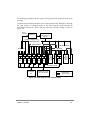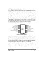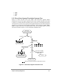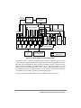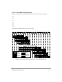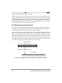
1
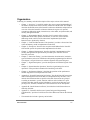
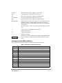
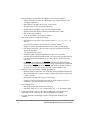
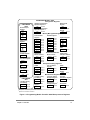
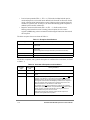
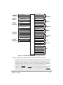
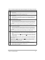
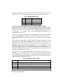
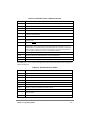
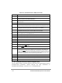
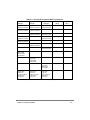
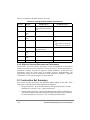
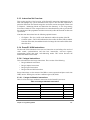
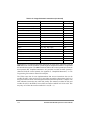
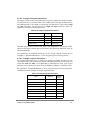
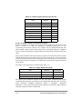
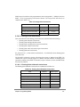
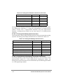
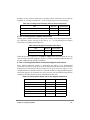
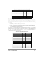
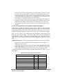
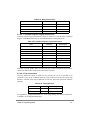
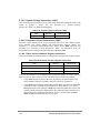
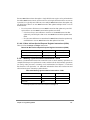
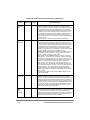
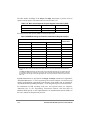
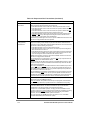
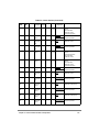
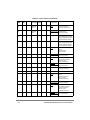
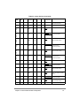
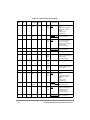
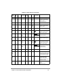
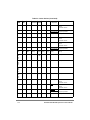
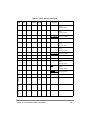
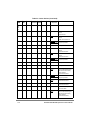
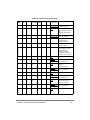
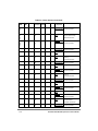
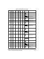
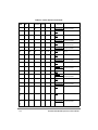
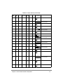
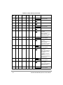
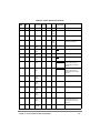
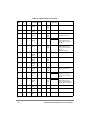
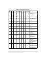
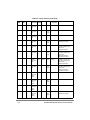
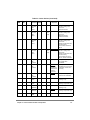
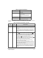
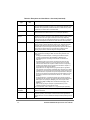
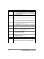
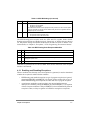
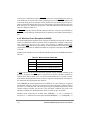
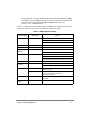
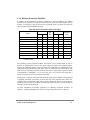
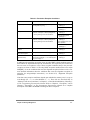
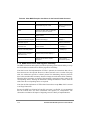
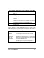
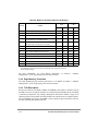
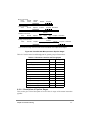
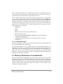
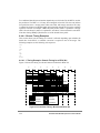
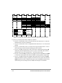
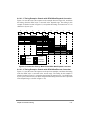
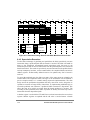
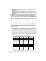
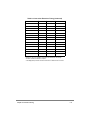
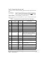
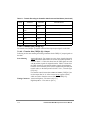
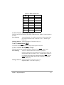
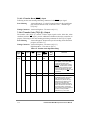
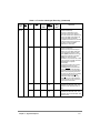
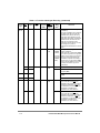
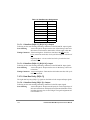
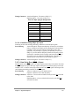
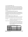
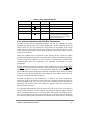
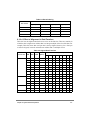
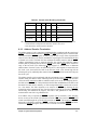
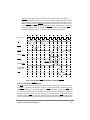
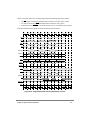
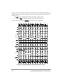
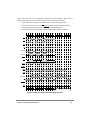
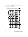
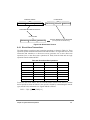
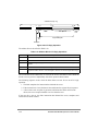
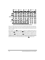
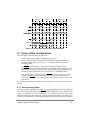
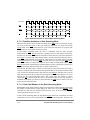
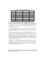
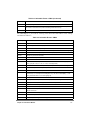
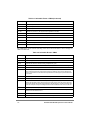
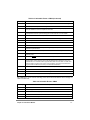
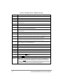
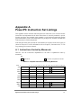
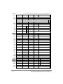
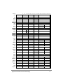
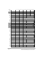
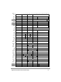
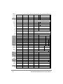
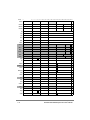
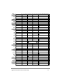
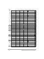
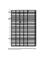
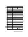
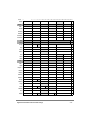
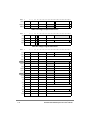
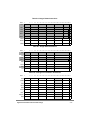
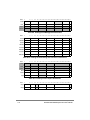
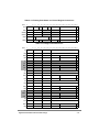
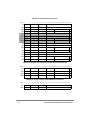
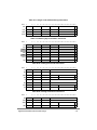
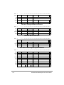
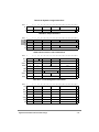
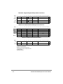
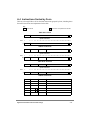
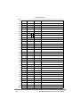
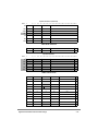
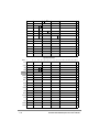
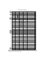
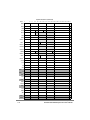
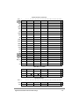
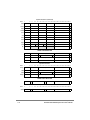
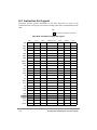
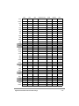
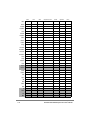
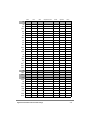
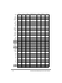
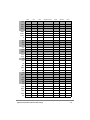
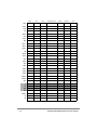
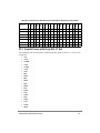
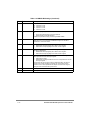
Table 4-3. MSR Bit Settings (Continued)
Bit(s)
Name
Description
18
FP
Floating-point available
0
The processor prevents dispatch of floating-point instructions, including floating-point
loads, stores, and moves.
1
The processor can execute floating-point instructions, and can take floating-point enabled
exception type program exceptions.
19
ME
Machine check enable
0
Machine check exceptions are disabled.
1
Machine check exceptions are enabled.
20
FE0
IEEE floating-point exception mode 0 (See Table 4-4).
21
SE
Single-step trace enable
0
The processor executes instructions normally.
1
The processor generates a single-step trace exception upon the successful execution of
the next instruction (unless that instruction is an rfi instruction). Successful execution
means that the instruction caused no other exception.
22
BE
Branch trace enable
0
The processor executes branch instructions normally.
1
The processor generates a branch type trace exception upon the successful execution of
a branch instruction.
23
FE1
IEEE floating-point exception mode 1 (See Table 4-4).
24
—
Reserved. This bit corresponds to the AL bit of the POWER architecture.
25
IP
Exception prefix. The setting of this bit specifies whether an exception vector offset is
prepended with Fs or 0s. In the following description, nnnnn is the offset of the exception.
0
Exceptions are vectored to the physical address 0x000n_nnnn.
1
Exceptions are vectored to the physical address 0xFFFn_nnnn.
26
IR
Instruction address translation
0
Instruction address translation is disabled.
1
Instruction address translation is enabled.
For more information see Chapter 5, “Memory Management.”
27
DR
Data address translation
0
Data address translation is disabled.
1
Data address translation is enabled.
For more information see Chapter 5, “Memory Management.”
28
—
Reserved, full function.
29
PM
Performance monitor marked mode
0
Process is not a marked process.
1
Process is a marked process.
This bit is specific to the 604e, and is defined as reserved by the PowerPC architecture. For
more information about the performance monitor, see Section 4.5.13, “Performance Monitoring
Interrupt (0x00F00).”
4-8
PowerPC 604e RISC Microprocessor User’s Manual