1
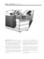
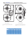
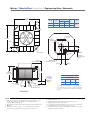
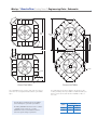
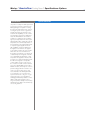
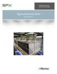
Lenntech
/ QuadraFlow
Cooling Tower /
[email protected] Tel. +31-152-610-900
www.lenntech.com Fax. +31-152-616-289
Engineering Data & Specifications
Marley / QuadraFlow Cooling Tower / Table of Contents
Engineering Data
Schematic
Support
Freeze Prevention
Environmental
Application
5
5
13
14
15
Specifications / Base
Base
Thermal Performance
Performance Warranty
Construction
Fill, Louvers and Drift Eliminators
Mechanical Equipment
Hot Water Distribution System
Casing, Top Deck and Fan Cylinder
Cold Water Collection Basin
Warranty
Scope of Work
16
16
16
17
18
19
20
20
20
21
21
Specifications / Options
Control Options
Control System
Vibration Limit Switch
Basin Heater
Variable Speed Drive
22
23
23
25
Marley / QuadraFlow Cooling Tower /
T
he Marley QuadraFlow® is a molded fiberglass, factory
fabricated, field erected, general purpose crossflow cooling
tower, designed to serve all normal cooling water systems—as
well as those systems whose water quality would jeopardize
the life expectancy of a galvanized cooling tower. In some
locations, the quality of the circulating water is very poor.
This can be because of the character of the makeup water
(brackish, acidic, alkaline, etc.), or because of contamination by
the product being cooled. In many cases, it is because of poor
air quality at the site. Cooling towers being ideal air washers,
the cooling tower water soon mimics the quality of the air.
The left hand column of pages 15 thru 23 provides text for
the various specification paragraphs, whereas the right hand
column comments on the meaning of the subject matter and
explains its value.
4
Pages 15 thru 20 indicate those paragraphs which will
result in the purchase of a tower that will not only accomplish
the specified thermal performance, but will include normal
operation and maintenance enhancing features. Also on these
pages are paragraphs intended to add those features and
components that will customize the tower to meet the user's
requirements.
Space does not permit definition and explanation of all the
possible options that can be applied to the QuadraFlow. We
realize that you, the purchaser, must be happy with the tower
and its characteristics, and we are prepared to provide—or
provide for—any reasonable enhancement that you are willing
to define and purchase.
Your needs will become part of the continuing evolution of
this Marley product line.
Marley / QuadraFlow Cooling Tower / Engineering Data : Schematic
5
W
INLET
A
6" MIN.
Model
A
W
Nominal
Tons
Dimensions
note 2
W
H
S
A
21120
129-183
12'-8 1⁄8"
7'-1 3⁄4"
7'-2 3⁄8"
21220
186-211
12'-8 ⁄8"
8'5"
21320
204-256
12'-8 1⁄8"
9'-9 1⁄4"
22120
243-304
14'-0 5⁄8"
22220
312-425
14'-0 5⁄8"
23120
390-475
16'-8 1⁄8"
9'-10 1⁄2"
23220
419-548
16'-8 1⁄8"
11'-2 3⁄4"
1
Outlet
8"
10"
10"
12"
2 @ 8"
14"
hp
C
2'-10 1⁄8"
2'-4 13⁄16"
4 1⁄8"
5-15
8'-5 ⁄16"
2'-10 ⁄8"
2'-4 ⁄16"
4 1⁄8"
10-15
9'-9 1⁄4"
2'-10 1⁄8"
2'-4 13⁄16"
4 1⁄8"
10-20
8'-6 1⁄4"
8'-6 3⁄16"
2'-7 9⁄16"
2'-8 7⁄8"
7 1⁄8"
10-20
9'-10 1⁄2"
9'-10 3⁄8"
2'-7 9⁄16"
2'-8 7⁄8"
7 1⁄8"
15-40
9'-9 5⁄8"
3'-2 9⁄16"
2'-8 7⁄8"
8 15⁄16"
20-40
11'-1 13⁄16"
3'-2 9⁄16"
2'-8 7⁄8"
8 15⁄16"
20-50
9
Inlet
Motor
B
1
13
note 5
MAKE UP NOTE 3
MOTOR
LOCATION
ACCESS
COVER
DRAIN
2" DIA.
CL
TOP OF
FAN GUARD
USE FOR
STATIC LIFT
TOP OF
SUPPORT
OVERFLOW
4" DIA.
TOP OF
SUPPORT
BY OTHERS
COLLECTION
BASIN
2'-6" MIN.
CL C
CL
B
CL
B
S
H
CL
CL
OUTLET
B
ROOF OR
GRADE
OUTLET
Use this data for preliminary layouts only. Obtain
current drawing from your sales representative.
Maximum Sump Capacities - GPM
Outlet Diameter
Model
The Marley UPDATE web-based selection software
— available at spxcooling.com — provides
QuadraFlow model recommendations based on
customer's specific design requirements.
6"
8"
10"
12"
14"
21000
440
770
1215
—
—
22000
—
875
1400
2025
—
23000
—
960
1500
2180
2610
NOTE
1. Dimensions shown are for preliminary layout only. Obtain current
engineering drawings or CAD files from your Marley sales
representative for final layout.
2. Nominal tons are based upon 95°F HW, 85°F CW, 78°F WB, and 3
GPM/ton.
3. Makeup connection may be 1" or 2" diameter, depending upon tower
heat load, water pressure, and desired connections.
4. All table data is per cell.
5. 21000 and 22000 models require only one inlet per cell and inlet
piping may be located at any of the four tower corners. 23000
models whose design GPM is 2025 or less may use a single 10"
inlet. Above 2025 GPM, two 8" inlets are required, located 180°
apart. Subtract 2" from “S” dimensions. Locating inlet riser directly
behind motor is not recommended due to restrictions placed on
motor access and removal.
6. All piping loads must be supported independent of tower.
7. All piping and supports are by others.
8. Outlet diameters shown are for maximum GPM. Smaller outlet
diameters may be appropriate.
note 8
Marley / QuadraFlow Cooling Tower / Engineering Data : Schematic
W
6
L
G
J
F D
E MIN
A
1'-0" MIN
A
INLET
INLET
PLAN—TWO CELL
PLAN—MULTICELL
Two-cell installations may conform to either of the two schemes
shown here. Choose the pattern that best fits into your available
space.
The multicell scheme shown here applies to any number of cells.
Contact your Marley sales representative for additional details if you
prefer to use the scheme at the left for an installation of three or
more cells.
Dimensions
Model
W
L
A
D
E
21120
12'-8 1⁄8"
14'-1 3⁄4"
2'-10 1⁄8"
28'-8 1⁄4"
21220
12'-8 1⁄8"
14'-1 3⁄4"
2'-10 1⁄8"
29'-2 1⁄4"
21320
12'-8 ⁄8"
14'-1 ⁄4"
2'-10 ⁄8"
1
3
1
F
G
J
9'-0 1⁄4"
3'-4"
7'-0 7⁄8"
2'-1 9⁄16"
9'-6 1⁄4"
3'-10"
7'-0 7⁄8"
2'-1 9⁄16"
29'-7 ⁄4"
9'-11 ⁄4"
4'-3"
7'-0 ⁄8"
2'-1 9⁄16"
1'-10"
1
1
7
22120
14'-0 ⁄8"
16'-1 ⁄8"
2'-7 ⁄16"
32'-4 ⁄4"
9'-6 ⁄8"
4'-3"
8'-0 ⁄16"
22220
14'-0 5⁄8"
16'-1 1⁄8"
2'-7 9⁄16"
32'-10 1⁄4"
10'-0 1⁄8"
4'-9"
8'-0 9⁄16"
1'-10"
23120
16'-8 1⁄8"
18'-2 7⁄8"
3'-2 9⁄16"
38'-2 1⁄4"
11'-3 1⁄8"
4'-10"
9'-1 7⁄16"
1'-10 7⁄16"
23220
16'-8 1⁄8"
18'-2 7⁄8"
3'-2 9⁄16"
38'-7 1⁄4"
11'-8 1⁄8"
5'-3"
9'-1 7⁄16"
1'-10 7⁄16"
5
1
9
1
1
9
Marley / QuadraFlow Cooling Tower / Engineering Data : Schematic
24'-6"
7468mm
6" MIN.
3'-11"
Model
Nomianal
Tons
note 2
H
S
24120
531-836
12'-8 1⁄2"
9'-8 3⁄16"
15-60
24220
796-1047
16'-1"
13'0 ⁄16"
25-60
1194mm
Dimensions
Motor
hp
11
7
Inlet
2 @ 10"
MAKE UP
NOTE 3
24'-6"
ACCESS
COVER
CL
INLET
3'-6 1/16"
CL
3'-11"
1'-1 7/8"
MOTOR
352mm
SUMP
TOP OF
FAN CYLINDER
OVERFLOW
AND DRAIN 4" DIA.
CL
FACE OF
SUMP OUTLET
NOTE 9
CL
3'-6 1/16"
1068mm
H
S
USE FOR
STATIC LIFT
CL
TOP OF
SUPPORTS
BY OTHERS
COLLECTION
BASIN
CL
CL
3'-6 1/16"
1068mm
1'-4 1/16"
2'-6" MIN.
ROOF OR
GRADE
Maximum Sump Capacities - GPM
Outlet Diameter
8"
10"
12"
14"
1550
2450
3500
4250
408mm
For gravity flow applications, outlet piping must
drop vertically out of tower a sufficient distance
to overcome all head losses within outlet piping
system.
OUTLET SUMP
DRAIN 1/2" DIA.
ELEVATION
NOTE
1 Dimensions shown are for preliminary layout only. Obtain current
engineering drawings or CAD files from your Marley sales
representative for final layout.
2 Nominal tons are based upon 95°F HW, 85°F CW, 78°F WB, and 3
GPM/ton.
3 Makeup connection may be 1" or 2" diameter, depending upon
tower heat load, water pressure, and desired connections.
4
5
6
7
All table data is per cell.
All piping loads must be supported independent of tower.
All piping and supports are by others.
Locating inlet riser directly behind motor is not recommended due
to restrictions placed on motor access and removal.
8 Outlet sump may be installed rotated 90° or 180° provided outlet
piping will clear tower support.
Marley / QuadraFlow Cooling Tower / Engineering Data : Schematic
24'-6"
7468mm
8
27'-5 9/16"
8371mm
13'-813/16"
4186mm
1'-11 3/8"
594mm
3'-11"
D W
1194mm
1'-0" MIN
INLET
INLET
3'-11"
PLAN—TWO CELL
Two-cell installations may conform to either of the two schemes
shown here. Choose the pattern that best fits into your available
space.
Use this data for preliminary layouts only. Obtain
current drawing from your sales representative.
The Marley UPDATE web-based selection software
— available at spxcooling.com — provides
QuadraFlow model recommendations based on
customer's specific design requirements.
PLAN—MULTICELL
The multicell scheme shown here applies to any number of cells.
Contact your Marley sales representative for additional details if you
prefer to use the scheme at the left for an installation of three or
more cells.
Model
Dimensions
D
W
24120
4'-3"
53'-3"
24220
5'-8"
54'-8"
Marley / QuadraFlow Cooling Tower / Engineering Data: Support
M
P
CL ANCHOR
BOLT
CL ANCHOR
BOLT
ANCHOR CL
BOLT
9
Dimensions
Model
M
P
7'-7 1⁄2"
7'-1 1⁄2"
21120
21220
P M
Wind / Seismic Loads lb
Max. Vertical
Reaction at
Anchor
Max. Horiz. Reaction at Anchor
10715
2934
664 / 2790
671 / 2679
11016
3009
959 / 3543
807 / 2754
11358
3121
1331 / 4213
950 / 2840
22120
14400
3881
921 / 3499
906 / 3600
23120
ANCHOR CL
BOLT
Maximum
Operating
Load at
Anchor
lb
21320
22220
SEE SUPPORT DETAIL.
TYPICAL FOUR PLACES
Maximum
Operating
Wt./Cell
lb
23220
9'-0 1⁄8"
9'-4 5⁄8"
8'-6 1⁄8"
8'10 5⁄8"
15159
4264
1279 / 4496
1067 / 3790
22465
6040
1625 / 6045
1075 / 5616
23120
6245
1860 / 7347
1230 / 5780
4" MIN
2"
1" MIN
CL
4" MIN
2"
BEAM
CL
1" MIN
1" MIN
CL
CL
1" MIN
1" MIN
CL
1" MIN
CL
CL
2" 4" MIN
2" 4" MIN
CL
1" MIN
1" MIN
ANCHOR
BOLT
COLUMN
ANCHOR
BOLT
BEAM SUPPORT DETAIL
Beam support option. 4" by 4" minimum bearing area to be
provided by others at each anchor bolt location. Beam may be
rotated 90°.
COLUMN SUPPORT DETAIL
Column (pier) support option. 4" by 4" minimum bearing area to be
provided by others at each anchor bolt location.
NOTE
1 Dimensions and details shown are for preliminary layout only. Obtain
current engineering drawings or CAD files from your Marley sales
representative for final layout.
2 The base of each QuadraFlow tower consists of a grid of galvanized
steel beams as part of the tower assembly. Minimal additional support
is required at the anchor bolt locations.
•Additionalsupport,design,construction,plusanchorbolthardware
by others.
•5⁄8" diameter anchor bolts are required. Projection of anchor bolts is
2 1⁄2" maximum, 1 1⁄2" minimum.
•Anchorpointsmustbeframedflushandlevelattop.Maximum
beam deflection to be 1/360" of span, not to exceed 1⁄2" at anchor
bolts.
3 Maximum operating weight occurs with basin full to overflow level.
Actual operating weight varies with GPM and piping scheme.
Operating water levels in excess of recommended levels can result in
loads exceeding values shown.
4 Consult your Marley sales representative for additional instructions if
tower is to be supported directly on vibration isolators.
5 Wind loads are based on 30 psf and are additive to operating loads.
Reactions due to seismic loads are calculated on the
basis of a 1g lateral load and are additive to operating loads.
Marley / QuadraFlow Cooling Tower / Engineering Data: Support
CL ANCHOR
BOLT
R
R
71mm
2 13/16"
V
CL ANCHOR
BOLT
CL ANCHOR
BOLT
ANCHOR CL
BOLT
CL ANCHOR
BOLT
ANCHOR CL
BOLT
M
P
10
R
P
M
V
SEE SUPPORT DETAIL.
TYPICAL FOUR PLACES
ANCHOR CL
BOLT
ANCHOR CL
BOLT
R
U
ANCHOR CL
BOLT
CL ANCHOR
BOLT
T
SUPPORT PLAN—TWO CELL
SUPPORT PLAN—MULTICELL
Dimensions
Model
M
P
R
V
T
U
21120
7'-7 1⁄2"
7'-1 1⁄2"
5'-1 7⁄8"
10'-0 7⁄8"
8'-4 5⁄8"
4'-7 3⁄16"
21220
7'-7 1⁄2"
7'-1 1⁄2"
5'-1 7⁄8"
10'-0 7⁄8"
8'-10 5⁄8"
4'-7 3⁄8"
21320
7'-7 ⁄2"
7'-1 ⁄2"
5'-1 ⁄8"
10'-0 ⁄8"
9'-3 ⁄8"
4'-7 3⁄8"
22120
9'-0 ⁄8"
8'-6 ⁄8"
6'-1 ⁄8"
12'-0 ⁄4"
9'-3 ⁄8"
4'-7 1⁄16"
22220
9'-0 1⁄8"
8'-6 1⁄8"
6'-1 5⁄8"
12'-0 1⁄4"
9'-9 1⁄2"
4'-7 1⁄16"
23120
9'-4 5⁄8"
8'-10 5⁄8"
6'-4 13⁄16"
12'-6 5⁄8"
12'-1 1⁄2"
6'-2 7⁄16"
23220
9'-4 5⁄8"
8'-10 5⁄8"
6'-4 13⁄16"
12'-6 5⁄8"
12'-6 1⁄2"
6'-2 7⁄16"
1
1
1
1
7
5
7
1
5
5
MIN
Marley / QuadraFlow Cooling Tower / Engineering Data: Support
4'-5 1/4"(1352mm)
CL CL ANCHOR
BOLT
M
ANCHOR CL CL
BOLT
11
CL CL ANCHOR
BOLT
P
4'-5 1/4"
Dimensions
P M
Model
24121 – 24127
P
14'-1 1⁄8"
13'-7 1⁄8"
Max. Vert.
Reaction at
Anchor
Max. Horiz.
Reaction at
Anchor
48825
7355
4090 / 14844
1330 / 5852
48845
7610
7800 / 19809
1815 / 6105
ANCHOR CL CL
BOLT
24221 – 24225
M
Wind / Seismic Loads lb
Maximum
Operating
Load at
Anchor
lb
Maximum
Operating
Wt./Cell
lb
4'-5 1/4"
SEE SUPPORT DETAIL.
TYPICAL 12 PLACES
4" MIN
2"
1" MIN
CL
4" MIN
2"
BEAM
CL
1" MIN
1" MIN
CL
CL
1" MIN
1" MIN
CL
1" MIN
CL
CL
2" 4" MIN
2" 4" MIN
CL
1" MIN
1" MIN
ANCHOR
BOLT
BEAM SUPPORT DETAIL
Beam support option. 4" by 4" minimum bearing area to be
provided by others at each anchor bolt location. Beam may be
rotated 90°.
ANCHOR
BOLT
COLUMN
COLUMN SUPPORT DETAIL
Column (pier) support option. 4" by 4" minimum bearing area
to be provided by others at each anchor bolt location.
NOTE
1 Dimensions and details shown are for preliminary layout only. Obtain
current engineering drawings or CAD files from your Marley sales
representative for final layout.
2 The base of each QuadraFlow tower consists of a grid of galvanized
steel beams as part of the tower assembly. Minimal additional support
is required at the anchor bolt locations.
•Additionalsupport,design,construction,plusanchorbolthardware
by others.
•5⁄8" diameter anchor bolts are required. Projection of anchor bolts is
2 ¹⁄2" maximum, 1¹⁄2" minimum.
•Anchorpointsmustbeframedflushandlevelattop.Maximum
beam deflection to be 1/360" of span, not to exceed 1⁄2" at anchor
bolts.
3 Maximum operating weight occurs with basin full to overflow level.
Actual operating weight varies with GPM and piping scheme.
Operating water levels in excess of recommended levels can result in
loads exceeding values shown.
4 Consult your Marley sales representative for additional instructions if
tower is to be supported directly on vibration isolators.
5 Wind loads are based on 30 psf and are additive to operating loads.
Reactions due to seismic loads are calculated on the
basis of a 1g lateral load and are additive to operating loads.
Marley / QuadraFlow Cooling Tower / Engineering Data: Support
M
P
4'-5 1/4"(1352mm)
CL CL ANCHOR
BOLT
R
ANCHOR CL CL
BOLT
6'-3 5/16"
R
1913mm
2 13/16"
71mm
CL CL ANCHOR
BOLT
ANCHOR CL CL
BOLT
3'-3 1/16"
12
3'-0 1/4"
3'-3 1/16"(992mm)
CL CL ANCHOR
BOLT
921mm
CL CL
3'-3 1/16"
CL ANCHOR
BOLT
4'-5 1/4"
CL CL ANCHOR
BOLT
ANCHOR CL CL
BOLT
CL
S
P M
4'-5 1/4"
992mm
SUPPORT PLAN—TWO CELL
Model
24120
24220
SUPPORT PLAN—MULTICELL
Dimensions
M
14'-1 1⁄8"
R
2'-3 3/16" (691mm) MIN 3'-3 1/16"
T
CL
SEE SUPPORT DETAIL.
TYPICAL 12 PLACES
R
P
13'-7 1⁄8"
R
6'-8 1⁄2"
S
19'-1 1⁄4"
T
6'-1 3⁄8"
7'-6 3⁄8"
Marley / QuadraFlow Cooling Tower / Engineering Data: Freeze Prevention
When the ambient air temperature falls below 32°F, the water in a
cooling tower can freeze. Marley Technical Report #H-003 “Operating
Cooling Towers in Freezing Weather” describes how to prevent freezing
during operation. Ask your Marley sales representative for a copy.
During shutdown, water collects in the cold water basin and may
freeze solid. You can prevent freezing by adding heat to the water left
in the tower—or, you can drain the tower and all exposed pipework at
shutdown.
Basin Heater KW Selection
Ambient
Temp ºF
+30º
Electric Basin Heaters
An automatic basin water heater system is available, consisting of
the following components:
•
•
+20º
Stainless steel electric immersion heater(s) mounted on stainless
steel plates on the floor of the collection basin.
NEMA 4 enclosure containing:
+10º
—Magnetic contactor to energize heater.
—Transformer to convert power supply to 24 volts for control circuit.
—Solid state circuit board for temperature and low-water cutoff.
Enclosure may be mounted on the side of the tower.
0º
Model
Phase and Voltage
1/208
Control probe in the collection basin to monitor
water temperature and level.
Note: any exposed piping that is still filled with water at shutdown—
including the makeup water line—should be electrically traced and
insulated (by others).
Indoor Storage Tank
With this type of system, water flows from an indoor tank, through
the load system, and back to the tower, where it is cooled. The cooled
water flows by gravity from the tower to the tank located in a heated
space. At shutdown, all exposed water drains into the tank, where it is
safe from freezing.
-20º
-30º
1/480
3/208
3/240
3
3
22000
4.5
4.5
23000
6
6
24000
—
15
21000
6
6
22000
6
6
23000
9
9
24000
—
21
21000
7.5
7.5
22000
23000
9
—
12
12
—
2@15
21000
9
9
22000
—
23000
12
12
15
—
22000
23000
—
—
—
2@18
—
12
12
—
—
15
2@9
24000
—
21000
—
2@9
2@21 (2)
2@21
15
22000
—
—
18
18
23000
—
—
2@12
2@12
24000
—
4@15 (2)
21000
—
15
22000
23000
24000
—
—
—
—
3/480
9
—
24000
21000
-10º
1/240
21000
24000
•
13
18
2@12
2@12
—
—
4@18 (2)
Except where (2) is indicated, one set of controls will handle the required
number of heaters. Where (2) is indicated, however, two sets of controls are
required per cell.
Marley / QuadraFlow Cooling Tower / Environmental
Sound Control
Sound produced by a QuadraFlow tower operating in an unobstructed environment will meet all but the most restrictive noise
limitations—and will react favorably to natural attenuation. Where the
tower has been sized to operate within an enclosure, the enclosure
itself will have a damping effect on sound. Sound also declines with
distance—by about 5 dBA each time the distance doubles. Where
noise at a critical point is likely to exceed an acceptable limit, several
options are available—listed below in ascending order of cost impact:
•
In many cases, noise concerns are limited to nighttime, when
ambient noise levels are lower and neighbors are trying
to sleep. You can usually resolve these situations by using
two-speed motors in either 1800/900 or 1800/1200 RPM
configuration—operating the fans at reduced speed without
cycling “after hours”. The natural nighttime reduction in wetbulb temperature makes this a very feasible solution in most
areas of the world, but the need to avoid cycling may cause
the cold water temperature to vary significantly.
14
As suggested in the aforementioned Technical Report, it may also
be advisable to specify a design wet-bulb temperature 1°F higher
than normal to compensate for potential recirculation initiated by the
enclosure. You’ll benefit from discussing your project with your Marley
sales representative.
System Cleanliness
Cooling towers are very effective air washers. Atmospheric dust
able to pass through the relatively small louver openings will enter
the circulating water system. Increased concentrations can intensify
system maintenance by clogging screens and strainers—and smaller
particulates can coat system heat transfer surfaces. In areas of low
flow velocity—such as the cold water basin—sedimentary deposits can
provide a breeding ground for bacteria.
In areas prone to dust and sedimentation, you should consider
installing some means for keeping the cold water basin clean. Typical
devices include side stream filters and a variety of filtration media.
Water Treatment
•
The Marley Variable Speed Drive automatically minimize the
tower’s noise level during periods of reduced load and/or
reduced ambient temperature without sacrificing the system’s
ability to maintain a constant cold water temperature. This is a
relatively inexpensive solution, and can pay for itself quickly in
reduced energy costs.
•
Where noise is a concern at all times—for example, near a
hospital—the best solution is to oversize the tower so it can
operate continuously at reduced (1200 or 900 RPM) motor
speed. Typical sound reductions are 7 dBA at 2⁄3 fan speed or
10 dBA at 1⁄2 fan speed.
•
Extreme cases may require inlet and discharge sound attenuator sections—however, the static pressure loss imposed by
attenuators may necessitate an increase in tower size. This is
the least desirable approach because of the significant cost
impact—and because of the obstruction to normal maintenance procedures.
To control the buildup of dissolved solids resulting from water
evaporation, as well as airborne impurities and biological contaminants
including Legionella, an effective consistent water treatment program
is required. Simple blowdown may be adequate to control corrosion
and scale, but biological contamination can only be controlled with
biocides.
An acceptable water treatment program must be compatible with
the variety of materials incorporated in a cooling tower—ideally the
pH of the circulating water should fall between 6.5 and 8.0. Batch
feeding of chemicals directly into the cooling tower is not a good
practice since localized damage to the tower is possible. Specific
startup instructions and additional water quality recommendations
can be found in the QuadraFlow User Manual which accompanies
the tower and also is available from your local Marley sales representative. For complete water treatment recommendations, consult a
competent, qualified water treatment supplier.
Your Marley sales representative will help you meet your sound
requirements.
Enclosures
Occasionally, cooling towers are located inside architectural
enclosures for aesthetic reasons. Although QuadraFlow towers adapt
well to enclosures, the designer must realize the potential impact of a
poorly arranged enclosure on the tower’s performance and operation.
The designer must take care to provide generous air inlet paths, and
the tower’s fan cylinder discharge height should not be lower than
the elevation of the top of the enclosure. Obtain a copy of Marley
Technical Report #H-004 “External Influences on Cooling Tower
Performance” from your Marley sales representative.
CAUTION
The cooling tower must be located at such distance and direction
to avoid the possibility of contaminated tower discharge air
being drawn into building fresh air intake ducts. The purchaser
should obtain the services of a Licensed Professional Engineer
or Registered Architect to certify that the location of the tower
is in compliance with applicable air pollution, fire, and clean air
codes.
Marley / QuadraFlow Cooling Tower / Applicaton
Typical Applications
Applications Requiring Alternative Cooling Tower Selections
Although the QuadraFlow is a premium-value cooling tower
targeted for those applications that demand a high degree of corrosion resistance—as well as an aesthetically pleasing appearance—it
is routinely applied in virtually all normal systems requiring cold water
for the dissipation of heat. Some common applications include:
Certain types of applications are incompatible with any cooling
tower with PVC film fill—whether a QuadraFlow or a competitive
tower of similar manufacture. PVC is subject to distortion in high water temperatures, and the narrow passages typical of film-type fill are
easily clogged by turbid or debris-laden water. Some of the applications, which call for alternative tower designs are:
• Condenser water service for air conditioning and refrigeration systems. The QuadraFlow is especially adapt able to Free
Cooling applications.
•
Water temperatures exceeding 125°F—adversely affect the
service life and performance of normal PVC fill.
• Jacket water cooling for engines and air compressors.
•
Ethylene glycol content—can plug fill passages as slime and
algae accumulate to feed on the available organic materials.
•
Fatty acid content—found in processes such as soap and detergent manufacturing and some food processing—fatty acids
pose a serious threat for plugging fill passages.
•
Particulate carry over—often found in steel mills and cement
plants—can both cause fill plugging, and can build up to potentially damaging levels on tower structure.
•
Pulp carry over—typical of the paper industry and food processing where vacuum pumps or barometric condensers are
used—causes fill plugging which may be intensified by algae.
• Chemical and industrial processes.
• Batch cooling.
• Welder cooling.
• Plastic industry processes.
• Dairy, citrus, and other food industry processing where water
contamination is not likely to occur.
Marley Controls
SPX Cooling Technologies understands the capabilities and limitations of cooling towers and offers control systems that will assure
you the greatest benefit from your tower. Ranging in sophistication
from standard fan starters and disconnects to Programmable Logic
Controllers that work in conjunction with your building or process
system, these controls provide excellent energy management. Ask
for Marley Technical Report H-001-A “Cooling Tower Energy
and Its Management”.
For those of you who use your tower in the Free Cooling mode
Marley Technical Report H-002 “The Application of Cooling
Towers for Free Cooling”, these controls can help you maximize
the amount of time during the year that your expensive-to-operate
chiller does not have to be operated.
All motor controls are factory tested before shipping. Temperature controllers are provided to adjust fan operation to cooling
requirements.
Alternative Selections
In addition to the QuadraFlow, SPX Cooling Technologies offers a
full scope of products in various designs and capacities to meet the
special demands of specific applications.
Corrosion Resistance
•
Stainless steel construction—Marley stainless steel towers are
available in both crossflow and counterflow configurations to
solve site-related problems. They offer maximum resistance
to corrosion while meeting stringent building codes. PVC filmtype fill.
•
Sigma™ Series—available in wood, fiberglass, HDG steel or
stainless steel structure. Field-erected for medium to large
projects. Available in a wide range of sizes. Efficient PVC film
fill.
Splash-Fill Towers
•
Series 10 / Series 15—wood structure, fiberglass casing,
with splash-type fill. Similar capacities to Sigma series towers.
Proven in hundreds of installations. Excellent in “dirty water”
situations.
Special Installation
•
MS Series—custom-designed to fit your concrete enclosure.
PVC film-type fill and Marley industrial-quality internal components provide years of trouble-free service.
15
Marley / QuadraFlow Cooling Tower / Specifications: Base
Specifications
1.0
Base:
1.1
Furnish and install an induced-draft,
crossflow-type, field-erected, fiberglass
and stainless steel cooling tower of
_____ cell(s), as shown on plans. Cells
shall be similar and equal in all respects
to Marley QuadraFlow Model ________.
2.0
Thermal Performance:
2.1
The tower shall be capable of cooling
_____ GPM of water from _____ °F to
_____ °F at a design entering air wetbulb temperature of _____ °F. The thermal performance rating shall be Certified
by the Cooling Technology Institute.
3.0
Performance Warranty:
3.1
CTI Certification notwithstanding, the
cooling tower manufacturer shall guarantee that the cooling tower supplied
will meet the specified performance
conditions when the tower is installed
according to plan. If, because of a suspected thermal performance deficiency,
the owner chooses to conduct an onsite thermal performance test under the
supervision of a qualified, disinterested
third party in accordance with CTI or
ASME standards during the first year of
operation; and if the tower fails to perform within the limits of test tolerance;
then the cooling tower manufacturer will
pay for the cost of the test and will make
such corrections as are appropriate and
agreeable to the owner to compensate
for the performance deficiency.
Specification Value
■ Your specification base establishes the type, configuration, base material,
and physical limitations of the cooling tower to be quoted. During the planning and layout stages of your project, you will have focused your attention on a cooling tower selection that fits your space allotment, and whose
power usage is acceptable. Limitations on physical size and total operating
horsepower avoid the introduction of unforeseen operational and site-related
influences. Specifying the number of cells, and the maximum fan hp/cell will
work to your advantage.
Fans of induced draft towers are in the warm (non-freezing) leaving airstream of the tower. They accelerate the moist air upward to prevent recirculation from degrading the tower's thermal performance. In forced-draft
towers, the reverse is true, and recirculation happens routinely.
Crossflow towers have a spacious
plenum between banks of fill for easy
access to all of the tower's internal
components. Counterflow towers (one
manufacturer offers nothing else) provide
only cramped and awkward access to
the mechanical equipment, the drift eliminators, and the water distribution spray
system—and the very small access door
is up near the top of the tower!
■ CTI Certification means that the cooling tower has been tested under operating conditions and found to perform as rated by the manufacturer under
those circumstances. It assures the buyer that the tower is not intentionally
or inadvertently undersized by the manufacturer.
■ However, CTI certification alone is not sufficient to assure you that the cooling tower will perform satisfactorily in your situation. Certification is established under relatively controlled conditions, and cooling towers seldom
operate under such ideal circumstances. They are affected by nearby structures, machinery, enclosures, effluent from other sources, etc. Responsible
and knowledgeable bidders will take such site-specific effects into consideration in selecting the coolling tower—but the specifier must insist by the
written specification that the designer/manufacturer guarantee this “real
world” performance. Any reluctance on the part of the bidder should cause
you some concern.
16
Marley / QuadraFlow Cooling Tower / Specifications: Base
Specifications
4.0
Construction:
4.1
The cold water basin, structural columns,
hot water distribution basins, basin covers, top deck, fan cylinder, and access
door shall be formed of inert fiber-reinforced polyester (FRP), either molded or
pultruded. All hardware, with the exception of the supporting grillage, shall be
fabricated of 300 series stainless steel.
This shall include the mechanical equipment support structure, fan guards, and
all bolts, nuts and fasteners used in the
construction of the tower. Design criteria
for the tower structure and anchorage
shall be 30 psf (1.44 kPa) wind load.
Tower anchorage shall also meet a 1g
horizontal seismic load.
4.2
4.3
The tower shall be capable of withstanding water having a pH of 6.5 to 8.0; a
chloride content (NaCl) up to 750 ppm; a
sulfate content (SO4 ) up to 1200 ppm; a
calcium content (CaCO3) up to 800 ppm;
silica (SiO2) up to 150 ppm; and design
hot water temperatures up to 125°F
(51.7°C). The circulating water shall contain no oil, grease, fatty acids, or organic
solvents.
The specifications, as written, are intended to indicate those materials that will
be capable of withstanding the above
water quality in continuing service, as
well as the loads described in paragraph
4.1. They are to be regarded as minimum
requirements. Where component materials peculiar to individual tower designs
are not specified, the manufacturers shall
take the above water quality and load carrying capabilities into account in the selection of their materials of manufacture.
Specification Value
■ This combination of fiberglass and stainless steel provides complete protection against the degrading effects of corrosion. The molded shapes of
the fiberglass also provide an architecturally pleasing appearance that is
rare in a cooling tower.
The listed design values give you assurance that the tower can be
shipped, handled, constructed—and ultimately operated in a long term
hostile environment.
Section 1632 of the 1997 UBC, “Lateral Force on…Equipment
Supported by Structures,” states that the anchorage for permanent
equipment must resist the lateral seismic force. The structure for the
equipment is not required to resist the seismic force unless failure represents a life hazard. Life hazard is dependent on location and the process
supported. If you feel the need to have a compliant structure please consult SPX engineering.
Except for those unusual operating situations where the circulating water
may be so laden with suspended solids, algae, fatty acids, product fibers,
active organisms reflected in BOD, and the like that plugging of the fill
is a probability, reasonable attention to the construction materials and/or
their coatings is all that is normally required.
If extended longevity of the tower is required—or unusually harsh operating conditions are expected—consider specifying 316 stainless steel
components. Discuss the need for this with your local Marley sales representative.
17
Marley / QuadraFlow Cooling Tower / Specifications: Base
18
Specification Value
Specifications
5.0
Fill, Louvers and Drift Eliminators:
5.1
Fill shall be film-type, thermoformed of
15 mil (0.38 mm) thick PVC, with louvers
formed as part of each fill sheet. Fill shall
be suspended from stainless steel structural tubing supported from the tower
structure and intermediate stainless steel
panels, and shall be elevated at least 2"
(50.8 mm) above the floor of the cold
water basin to facilitate cleaning. Air inlet
faces of the tower shall be free of water
splash-out.
■ Louvers integral with the fill keep the flowing water within the confines
of the fill. The separate external louvers used by others permit water to
escape the fill and form ice or produce an unsightly situation adjacent to
the tower. If you plan to use your tower in the wintertime, particularly for
free cooling, integral louvers will put your operating concerns to rest.
5.2
Drift eliminators shall be PVC, triple-pass,
and shall limit drift losses to 0.005% or
less of the design water flow rate.
■ Drift rate varies with design water loading
and air rate, as well as drift eliminator depth
and number of directional changes. A drift
rate of 0.001% is readily available on many
standard models. If a lower rate is required,
please discuss with your Marley sales representative.
Drift Eliminators
Louvers
Fill sheets
Marley / QuadraFlow Cooling Tower / Specifications: Base
Specifications
6.0
Mechanical Equipment:
6.1
Fan(s) shall be propeller-type, incorporating heavy-duty blades of cast aluminum
or high-strength, inert composite material.
Fan blades shall be individually adjustable
and replaceable. Fan(s) shall be driven
through a rightangle, industrial-duty, oillubricated, geared speed reducer that
requires no oil changes for the first five
(5) years of operation. Speed reducers
employing pulleys and belts will not be
permitted.
6.2
Motor(s) shall be ____ hp maximum,
TEFC, 1.15 service factor, and specially
insulated for cooling tower duty. Speed
and electrical characteristics shall be
1800 (1800/900) RPM, single-winding,
___ phase, ____ hertz, ____ volts.
6.3
Motor shall be located outside the humid
interior of the tower, within an alcove in
the tower's corner structure. The motor
shall be connected to the geared speed
reducer by a tubular stainless steel
driveshaft equipped with neoprene flexible coupling elements. A neoprene oil
gauge and drain line shall extend from
the gear reducer to the motor enclosure,
and shall be equipped with an easily visible oil sight glass. The mechanical equipment for each cell shall rest on a rigid
stainless steel box-beam assembly that
resists misalignment between the motor
and the gear reducer.
Specification Value
■ Propeller-type fans require only half the operating hp of blower-type fans.
However, they should be readily adjustable to permit compensation for
jobsite conditions that may tend to overload the motor.
Standard fan drives of other manufacturers may use V-belts. Considering
the size of fans involved—and the hp applied—this is not good design
practice. Gear drive is far more reliable and trouble free—and is not proprietary. It is currently offered as an additional cost option by principal
Marley competitors.
To reduce cost, some manufacturers may use TEAO motors, whose
only source of cooling is the flow of air produced by the cooling tower
fan. They are sometimes applied at hp significantly beyond their nameplate rating. Also, if they drive the fan through V-belts, they are probably
mounted in a shaft-vertical position. This is not good practice in the
moisture-laden airstream of a cooling tower because of the tendency of
moisture to invade bearings by flowing down the motor shaft.
Unless otherwise specified, motor speed will be 1800 RPM in 60 Hertz
areas and 1500 RPM in 50 Hertz areas. If you prefer the operating flexibility of two-speed operation, please specify the RPM to be 1800/900
(1500/750 in 50 Hertz regions). Incidentally, two speed motors are a far
better choice than separate “pony” motors which simply double the problems indicated above.
The value of a 5 year mechanical equipment warranty speaks for itself.
Except for the motor, all of the mechanical equipment on a Marley tower
is made by SPX Cooling Technologies. Cooling tower vendors who purchase commercial fans, gear reducers, driveshafts, etc. may require that
you deal directly with those commercial suppliers for warranty satisfaction.
19
Marley / QuadraFlow Cooling Tower / Specifications: Base
Specifications
7.0
Hot Water Distribution System:
7.1
An FRP distribution basin shall receive
hot water piped to each cell of the tower.
Each basin shall include one or more
inlet holes and grommets to accommodate appropriately sized inlet piping.
Removable, interchangeable polypropylene nozzles installed in the floor of
these basins shall provide full coverage
of the fill by gravity flow. The hot water
basin shall be covered by removable FRP
covers that keep out sunlight and give a
finished appearance to the tower.
8.0
Casing, Top Deck and Fan Cylinder:
8.1
Tower corner casings, top deck and fan
cylinder shall be fabricated of molded
FRP. Fan cylinders less than 60" (1524
mm) in height shall be equipped with
a conical, non-sagging, removable fan
guard, fabricated of welded 5⁄16" (8 mm)
and 7 gauge stainless steel rods.
9.0
Cold Water Collection Basin:
9.1
The cold water basin shall be molded
of FRP and sealed watertight. It shall
include a float-operated makeup valve, a
4" (102 mm) diameter overflow connection, and a depressed FRP sump complete with a stainless steel debris screen.
The top of the basin to the base of the fill
shall be covered with removable, heavy
gauge stainless steel screens to keep
airborne leaves and debris out of the circulating water system.
9.2:
The basin design shall allow for the
installation of warm water bypass lines, as
well as basin water level equalization lines
between towers, if necessary. The cooling
tower manufacturer shall provide drawings to facilitate the installation of these
features by others.
9.3
The cold water basin and tower shall be
supported by a structural beam assembly
of welded sections, provided and installed
by the cooling tower manufacturer. The
assembly sections shall be hot-dip galvanized after fabrication.
Specification Value
■ Gravity-flow distribution basins are a feature of crossflow type towers,
resulting in operating pump heads of from 10 to 20 feet less than that
encountered in counterflow towers, with their pressurized spray systems.
Also, these basins are out where they can be easily inspected—even
maintained—while the tower is in operation. Spray systems of counterflow
towers, sandwiched between the top of the fill and the drift eliminators,
are extremely awkward to access and maintain.
■ Marley Models 21000 thru 23000 are equipped with the fan guard
specified. 24000 Models have 5'-0" high, flared, velocity-recovery fan
cylinders.
■ Everything within the basin is of inert, noncorroding material.
Fiberglass towers can require very complicated support systems. To
avoid errors in design and fabrication, the steel in immediate support of
the basin should be provided by the cooling tower manufacturer. This
should simplify the foundation requirements such that primary support
can be accomplished by piers, if desired.
Not being in contact with the cooling tower water, the supports need not
be stainless steel, but they should be hot dip galvanized after fabrication.
20
Marley / QuadraFlow Cooling Tower / Specifications: Base
Specifications
10.0
Warranty:
10.1
The manufacturer shall warrant the entire
tower against failure in normal operation
for a period of five (5) years following
shipment to the site.
11.0
Scope of Work:
11.1
The cooling tower manufacturer shall be
responsible for the design, fabrication,
and delivery of materials to the project
site, and for the erection of the tower
over primary supports provided at the
proper elevation by others. Unless otherwise specified, all piping, pumps, controls,
and electrical wiring will be outside the
cooling tower manufacturer's scope of
work.
Specification Value
■ A tower that is capable of meeting these specifications should easily be
warrantable for five years. Please insist upon it! And, insist that the warranty cover all the tower, including the motor, gear reducer, (V-belts, if
you allow them), and all other pieces of mechanical equipment.
■ To assure proper fit-up of parts, and alignment of mechanical equipment,
it is recommended that erection be made a part of the cooling tower
manufacturer's contract. In any case, a comprehensive, illustrated Marley
assembly manual will be provided which pictorially identifies the tower
components—and provides step-by-step instructions designed to result in
a correctly assembled tower.
21
Marley / QuadraFlow Cooling Tower / Specifications: Options
Specifications
Specification Value
Control Options
Control System:
6.4
Add the following paragraph in the
Mechanical Equipment section: Each cell
of the cooling tower shall be equipped
with a UL listed control system in a
NEMA 3R or 4X outdoor enclosure capable of controlling single-speed or twospeed motors as required, and designed
specifically for cooling tower applications.
The panel shall include a main fused disconnect with an external operating handle, lockable in the off position for safety.
Across-the-line magnetic starters or solid
state soft-start starters as required shall
be controlled with a thermostatic or solid
state temperature controller. Door mounted selector switches shall be provided to
enable automatic or manual control and
wired for 120VAC control. Control circuit
to be wired out to terminal blocks for field
connection to a remote vibration switch
and for access to extra 120VAC 50VA
control power, overload trip alarms and
remote temperature control devices. The
temperature controller shall be adjustable
for the required cold water temperature.
If a thermostatic controller is used it shall
be mounted on the side of the tower with
the temperature sensing bulb installed in
the cold water basin using a suspension
mounting bracket. If a solid state temperature controller is used the controller will
be door mounted on the control panel.
The temperature controller will display
two temperatures, one for outgoing water
and the other for set point. Water temperature input shall be obtained using a
three-wire RTD with dry well in the outlet
water piping and wired back to the solid
state temperature controller in the control
panel.
■ If it is your opinion that the control system for the cooling tower should
be part of the tower manufacturer’s responsibility, we are in wholehearted
agreement with you. Who better to determine the most efficient mode
and manner of a tower’s operation—and to apply a system most compatible with it—than the designer and manufacturer of the cooling tower?
Marley variable speed drives are also available for the ultimate in temperature control, energy management, and mechanical equipment longevity.
22
Marley / QuadraFlow Cooling Tower / Specifications: Options
Specifications
Vibration Limit Switch:
6.5
Add the following paragraph in the
Mechanical Equipment section: A singlepole, double-throw vibration limit switch
in a NEMA 4 housing shall be installed
on the mechanical equipment support for
wiring into the owner’s control panel. The
purpose of this switch will be to interrupt
power to the motor in the event of excessive vibration. It shall be adjustable for
sensitivity, and shall require manual reset.
Basin Heater:
9.4
Add the following paragraph in the Cold
Water Basin section: Provide a system
of electric immersion heaters and controls for each cell of the tower to prevent
freezing of water in the collection basin
during periods of winter shutdown. The
system shall consist of a three-element,
stainless steel, electric immersion heater
welded to a 3/16" thick stainless steel
mounting plate, complete with a NEMA 4
terminal box. A NEMA 4 enclosure shall
house a magnetic contactor to energize
heaters; a transformer to provide 24 volt
control circuit power; and a solid state circuit board for temperature and low water
cutoff. A control probe shall be located in
the basin to monitor water level and temperature. The system shall be capable of
maintaining 40°F water temperature at an
ambient air temperature of ____ °F.
Specification Value
■ Unless specified otherwise, a Marley
M-5 vibration switch will be provided.
The requirement for manual reset
assures that the cooling tower will
be visited to determine the cause of
excessive vibration.
■ The basin heater components described at left represent our recommendation for a reliable automatic system for the prevention of basin freezing.
They are designed for installation at the jobsite.
Submerged in basin water, in which zinc ions are present, copper immersion heaters must not be used. Insist upon stainless
steel.
The ambient air temperature that you insert in the specifications should
be the lowest 1% level of winter temperature prevalent at site.
Fan Motor Variable Speed Drive:
Marley All Weather ACH550 System
6.4
Add the following paragraph in the
Mechanical Equipment section when
VFD is used with customers Building
Management System: A complete UL listed
Variable Speed Drive system in a NEMA
1 indoor, NEMA 12 indoor or NEMA 3R
outdoor enclosure shall be provided. The
VFD shall use PWM technology with IGBT
switching and integrated bypass design.
VFD out put switching shall not cause
mechanical issues with gearbox teeth or
drive shafts. The VFD shall catch a fan
spinning in the reverse direction without
tripping. The panel shall include a main
disconnect with short circuit protection and
external operating handle, lockable in the
■ Marley VFD drive systems are designed to combine absolute temperature
control with ideal energy management. The cooling tower user selects a
cold water temperature and the drive system will vary the fan speed to
maintain that temperature. Precise temperature control is accomplished
with far less stress to the mechanical equipment components. The
improved energy management provides fast payback. Indeed, many utilities offer generous rebates for users having installed VFD drives.
23
Marley / QuadraFlow Cooling Tower / Specifications: Options
Specifications
off position for safety. The VFD system shall
receive a speed reference signal from the
Building Management System monitoring
the tower fluid temperature. As an option to
receiving the speed reference signal from
a building management system, the drive
must have the capability to receive a 4-20
ma temperature signal from an RTD transmitter. The VFD shall have an internal PI
regulator to modulate fan speed maintaining set point temperature. The drive's panel
display shall be able to display the set-point
temperature and cold-fluid temperature on
two separate lines. The bypass shall include
a complete magnetic bypass circuit and
with capability to isolate the VFD when in
the bypass mode. Transfer to the bypass
mode shall be manual in the event of VFD
failure. Once the motor is transferred to
the by-pass circuit the fan motor will run at
constant full speed. The bypass circuit will
not modulate ON and OFF based on fluid
temperature. The application must be able
to handle very cold fluid temperatures while
the VFD is in a by-pass mode. Operator
controls shall be mounted on the front of
the enclosure and shall consist of start and
stop control, bypass/VFD selection, Auto/
Manual selections, manual speed control. To
prevent heating problems in the fluid cooloer fan motor and to assure proper gear
reducer lubrication the VFD system shall
de energize the motor once 25% motor
speed is reached and cooling is no longer
required. The fluid cooler manufacturer
shall supply VFD start-up assistance. Tower
vibration testing throughout the speed
range is required to identify and lockout any
natural frequency vibration levels which may
exceed CTI guidelines.
Specification Value
24
Marley / QuadraFlow Cooling Tower / Specifications: Options
Specifications
25
Specification Value
Marley Premium VFD System:
6.4
Add the following paragraph in the
Mechanical Equipment section: A
complete UL listed Variable Speed Drive
system in a NEMA 12 indoor or NEMA
3R outdoor enclosure shall be provided.
The VFD shall use PWM technology with
IGBT switching and integrated by-pass
design. The panel shall include a main
disconnect with short circuit protection
and external operating handle, lockable
in the off position for safety. The system
shall include a solid state, PID temperature
controller to adjust frequency output of the
drive in response to the tower cold water
temperature. The temperature of the cold
water and set point shall be displayed on
the door of the control panel. The by-pass
circuit shall include a complete magnetic
bypass that isolates the VFD when in the
bypass mode. Transfer to the bypass mode
shall be automatic in the event of VFD failure or for trip faults. The bypass contactor
shall be cycled on and off while operating in bypass, to maintain the set-point
temperature of the cold water. The drive
design shall be operated as a stand- alone
system or controlled with a building automation system. The BAS can be the normal source of control and the integrated
temperature controller may be used as a
backup to the building automation system.
Operator controls shall be mounted on
the front of the enclosure and shall consist of start and stop control, bypass/VFD
selector switch, Auto/Manual selector
switch, manual speed control, and solid
state temperature controller. An emergency bypass selector switch internal to
the panel allowing the cooling tower fan
motor to be run at full speed shall be furnished.
To prevent heating problems in the cooling tower fan motor and to assure proper
gear reducer lubrication the VFD system shall cycle the motor on/off when
the minimum allowable motor speed is
reached.
The cooling tower manufacturer shall
supply VFD start-up and tower vibration testing to identify and lock out any
vibration levels which may exceed CTI
guidelines.
Lenntech
[email protected] Tel. +31-152-610-900
www.lenntech.com Fax. +31-152-616-289
7401 WEST 129 STREET
OVERLAND PARK, KANSAS 66213
UNITED STATES
913 664 7400
[email protected]
spxcooling.com
In the interest of technological progress,
all products are subject to design and/or
material change without notice.
©2010 SPX Cooling Technologies, Inc.
Printed in USA | QF-TS-10