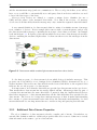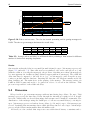
1
WISSPR
A Web-based Infrastructure for
Sensor Data Streams Sharing,
Processing and Storage
Master’s Thesis
Oliver Senn
[email protected]
Supervisor : Vlad Trifa
Professor : Friedemann Mattern
Institute for Pervasive Computing
Department of Computer Science
ETH Zürich
June 2010
Abstract
Hardware miniaturization, the increased speed of microchips and reduced energy consumption
allowed the development and deployment of many embedded (mobile) devices in the last ten
years. More and more of those devices are equipped with numerous sensors and an increasing
number of specialized sensor networks are installed worldwide. However, most existing deployments are isolated and the data is not merged in order to allow building mashups. This is
mostly due to the lack of an uniform and easy way to make sensor data available, to integrate,
and process it.
The thesis proposes a novel, distributed architecture (Wisspr ) that facilitates the advanced
interaction with sensor data. Wisspr supports publishing and sharing of sensor data over the
Web in the form of data streams. The representation of sensor data as streams and the use of
Web messaging protocols ease the development of (Web-based) sensor monitoring applications.
Additionally, Wisspr also provides mechanisms for storing sensor data, as well as for executing
continuous queries over the data. This three-fold functionality provides most applications with
the necessary mechanisms to interact with sensor data in a very easy, declarative way.
Wisspr allows to deal with many devices and high sensor sampling rates because it was
designed in a modular and scalable way. An important advantage of the modular design is the
use of specialized engines for publishing, storing and querying. This helps making Wisspr even
more scalable and flexible.
We demonstrate the performance and limitations of our prototype implementation by testing
it against several benchmarks. We also argue why our platform is suitable for a wide range of
potential applications by analyzing the requirements of a set of typical sensing applications.
Zusammenfassung
In den letzten 10 Jahren konnten, dank kompakterer Hardware, verbesserter Geschwindigkeit
der Microchips und reduzierter Energieaufnahme, viele eingebettete, oftmals mobile Geräte
entwickelt und eingesetzt werden. Ein immer grösser werdender Anteil dieser Geräte ist mit
verschiedenen Sensoren ausgestattet und eine zunehmende Zahl von spezialisierten Sensornetzen
werden weltweit installiert. Jedoch sind viele der derzeitigen Installationen voneinander isoliert
und die produzierten Daten werden nicht zusammen gebracht, um Mashups zu ermöglichen.
Dies liegt vor allem daran, dass ein einheitlicher and einfacher Weg fehlt, um die Sensordaten
verfügbar zu machen, einzubinden und zu analysieren.
Diese Arbeit schlägt eine neuartige, verteilte Architektur vor (genannt Wisspr ), die die Interaktion mit Sensordaten vereinfacht. Wisspr unterstützt das Publizieren und Bereitstellen
von Sensordaten über das Web in der Form von data streams. Die Verkörperung von Sensordaten als streams und der Gebrauch von Web-Messaging-Protokollen hilft die Entwicklung
von (Web-basierten) Kontrollsystemen fr Sensoren zu vereinfachen. Zusätzlich stellt Wisspr
Mechanismen zur Verfügung, die es erlauben Sensordaten zu speichern und kontinuierliche
Abfragen auszuführen. Diese drei Merkmale erlauben vielen Anwendungstypen die Interaktion
mit Sensordaten in einer sehr einfachen und deklarativen Art.
Wisspr kann mit vielen Geräten und hohen Abtastraten umgehen, da es in einer modularen und skalierbaren Art entworfen wurde. Ein wichtiger Vorteil des modularen Designs ist
die Verwendung von spezialisierten Software-Infrastrukturen für Messaging, Persistierung und
Abfragen. Dieser Punkt hilft zusätzlich, Wisspr skalierbar und flexibel zu machen.
Wir zeigen die Performanz und die Beschränkungen unserer Prototyp-Implementierung mittels mehreren Tests auf. Indem wir die Anforderungen von typischen Sensor-Applikationen
analysieren, bringen wir zusätzliche Argumente vor, weshalb die Plattform sich für den Einsatz
mit verschiedensten Typen von Applikationen eignet.
Table of contents
1 Introduction
1.1 Goals . . . . . . . . . . . . . . . . . . . . . . . . . . . . . . . . . . . . . . . . . .
1.2 Contributions . . . . . . . . . . . . . . . . . . . . . . . . . . . . . . . . . . . . . .
1.3 Outline . . . . . . . . . . . . . . . . . . . . . . . . . . . . . . . . . . . . . . . . .
2 Related Work & Motivation
2.1 Low-level Sensor Data Access . . . . .
2.1.1 Messaging for WSNs . . . . . .
2.2 Web-based Access to Sensor Data . . .
2.2.1 Alternatives to the Web Service
2.3 Stream Processing Engines . . . . . .
2.4 Web Messaging Protocols . . . . . . .
2.5 Motivation . . . . . . . . . . . . . . .
1
2
2
3
.
.
.
.
.
.
.
.
.
.
.
.
.
.
.
.
.
.
.
.
.
.
.
.
.
.
.
.
.
.
.
.
.
.
.
.
.
.
.
.
.
.
.
.
.
.
.
.
.
.
.
.
.
.
.
.
.
.
.
.
.
.
.
.
.
.
.
.
.
.
.
.
.
.
.
.
.
.
.
.
.
.
.
.
.
.
.
.
.
.
.
.
.
.
.
.
.
.
.
.
.
.
.
.
.
.
.
.
.
.
.
.
.
.
.
.
.
.
.
5
5
6
8
9
10
11
12
3 System Architecture
3.1 Target Use Cases . . . . . . . . . . . . . . . . . . . .
3.1.1 Static Data Analysis . . . . . . . . . . . . . .
3.1.2 Monitoring with Relaxed Latency Requirements
3.1.3 Monitoring with Small Latency Requirements .
3.1.4 (Near) Real-time Analysis . . . . . . . . . . .
3.2 A Modular Architecture . . . . . . . . . . . . . . . .
3.2.1 External Specialized Engines . . . . . . . . . .
3.3 Sensor Data Stream Semantics . . . . . . . . . . . .
3.3.1 Additional Data Stream Properties . . . . . .
3.4 Messaging Connector Module . . . . . . . . . . . . .
3.5 Storage Connector Module . . . . . . . . . . . . . . .
3.6 Query Processing Connector Module . . . . . . . . .
3.7 Integration with InfraWot . . . . . . . . . . . . . . .
3.8 Flexibility of the Architecture . . . . . . . . . . . . .
.
.
.
.
.
.
.
.
.
.
.
.
.
.
.
.
.
.
.
.
.
.
.
.
.
.
.
.
.
.
.
.
.
.
.
.
.
.
.
.
.
.
.
.
.
.
.
.
.
.
.
.
.
.
.
.
.
.
.
.
.
.
.
.
.
.
.
.
.
.
.
.
.
.
.
.
.
.
.
.
.
.
.
.
.
.
.
.
.
.
.
.
.
.
.
.
.
.
.
.
.
.
.
.
.
.
.
.
.
.
.
.
.
.
.
.
.
.
.
.
.
.
.
.
.
.
.
.
.
.
.
.
.
.
.
.
.
.
.
.
.
.
.
.
.
.
.
.
.
.
.
.
.
.
.
.
.
.
.
.
.
.
.
.
.
.
.
.
.
.
.
.
.
.
.
.
.
.
.
.
.
.
.
.
.
.
.
.
.
.
.
.
.
.
.
.
.
.
.
.
.
.
.
.
.
.
.
.
.
.
.
.
.
.
.
.
.
.
.
.
.
.
.
.
15
15
15
17
18
18
19
19
19
20
22
22
23
24
25
.
.
.
.
.
31
31
32
33
33
33
4 Implementation
4.1 Modularity through OSGi . . . . . .
4.2 RESTful Interfaces . . . . . . . . . .
4.3 Device Driver Extensions . . . . . . .
4.3.1 RESTful Data Transport . . .
4.3.2 OSGi Service Data Transport
.
.
.
.
.
. . . . . .
. . . . . .
. . . . . .
Approach
. . . . . .
. . . . . .
. . . . . .
.
.
.
.
.
.
.
.
.
.
.
.
.
.
.
.
.
.
.
.
.
.
.
.
.
.
.
.
.
.
.
.
.
.
.
.
.
.
.
.
.
.
.
.
.
.
.
.
.
.
.
.
.
.
.
.
.
.
.
.
.
.
.
.
.
.
.
.
.
.
.
.
.
.
.
.
.
.
.
.
.
.
.
.
.
.
.
.
.
.
.
.
.
.
.
.
.
.
.
.
.
.
.
.
.
.
.
.
.
.
.
.
.
.
.
.
.
.
.
.
.
.
4.3.3 Providing Extended Device Descriptions
4.3.4 Phidgets RFID driver . . . . . . . . .
4.4 Web Interface Module . . . . . . . . . . . . .
4.4.1 Restlet & Freemarker . . . . . . . . .
4.4.2 Bundle Service . . . . . . . . . . . . .
4.5 Wisspr-wide Configuration . . . . . . . . . . .
4.6 Messaging Connector Module . . . . . . . . .
4.6.1 Web-Messaging Protocol . . . . . . .
4.6.2 Device Driver Registry . . . . . . . . .
4.6.3 Frequency-based Data Streams . . . .
4.6.4 Instant Data Streams . . . . . . . . .
4.6.5 Senders . . . . . . . . . . . . . . . . .
4.6.6 Creation of Data Streams . . . . . . .
4.7 Storage Connector Module . . . . . . . . . . .
4.7.1 Creating a Data Stream Persistence . .
4.7.2 Engine Interface . . . . . . . . . . . .
4.7.3 Currently Supported Engines . . . . .
4.8 Query Processing Connector Module . . . . .
4.8.1 Registering a Query . . . . . . . . . .
4.8.2 Query Processing Engine Interface . .
4.8.3 Currently Supported Engines . . . . .
4.9 InfraWot Extensions . . . . . . . . . . . . . .
4.10 Support for the CometD Protocol . . . . . . .
5 System Evaluation
5.1 Benchmarking Framework . . . . . .
5.1.1 XML Configuration . . . . .
5.1.2 Hardware . . . . . . . . . . .
5.2 Device Simulator . . . . . . . . . . .
5.2.1 Implementation . . . . . . .
5.3 Experiments . . . . . . . . . . . . .
5.3.1 Coping with Many Devices .
5.3.2 Delay with High Load . . . .
5.3.3 Many Data Streams . . . . .
5.3.4 Influence of Complex Filtering
5.3.5 End-to-End Test . . . . . . .
5.3.6 Persisting Data Streams . . .
5.4 Discussion . . . . . . . . . . . . . .
.
.
.
.
.
.
.
.
.
.
.
.
.
.
.
.
.
.
.
.
.
.
.
.
.
.
.
.
.
.
.
.
.
.
.
.
.
.
.
.
.
.
.
.
.
.
. . . . . . .
. . . . . . .
. . . . . . .
. . . . . . .
. . . . . . .
. . . . . . .
. . . . . . .
. . . . . . .
. . . . . . .
Expressions
. . . . . . .
. . . . . . .
. . . . . . .
.
.
.
.
.
.
.
.
.
.
.
.
.
.
.
.
.
.
.
.
.
.
.
.
.
.
.
.
.
.
.
.
.
.
.
.
.
.
.
.
.
.
.
.
.
.
.
.
.
.
.
.
.
.
.
.
.
.
.
.
.
.
.
.
.
.
.
.
.
.
.
.
.
.
.
.
.
.
.
.
.
.
.
.
.
.
.
.
.
.
.
.
.
.
.
.
.
.
.
.
.
.
.
.
.
.
.
.
.
.
.
.
.
.
.
.
.
.
.
.
.
.
.
.
.
.
.
.
.
.
.
.
.
.
.
.
.
.
.
.
.
.
.
.
.
.
.
.
.
.
.
.
.
.
.
.
.
.
.
.
.
.
.
.
.
.
.
.
.
.
.
.
.
.
.
.
.
.
.
.
.
.
.
.
.
.
.
.
.
.
.
.
.
.
.
.
.
.
.
.
.
.
.
.
.
.
.
.
.
.
.
.
.
.
.
.
.
.
.
.
.
.
.
.
.
.
.
.
.
.
.
.
.
.
.
.
.
.
.
.
.
.
.
.
.
.
.
.
.
.
.
.
.
.
.
.
.
.
.
.
.
.
.
.
.
.
.
.
.
.
.
.
.
.
.
.
.
.
.
.
.
.
.
.
.
.
.
.
.
.
.
.
.
.
.
.
.
.
.
.
.
.
.
.
.
.
.
.
.
.
.
.
.
.
.
.
.
.
.
.
.
.
.
.
.
.
.
.
.
.
.
.
.
.
.
.
.
.
.
.
.
.
.
.
.
.
.
.
.
.
.
.
.
.
.
.
.
.
.
.
.
.
.
.
.
.
.
.
.
.
.
.
.
.
.
.
.
.
.
.
.
.
.
.
.
.
.
.
.
.
.
.
.
.
.
.
.
.
.
.
.
.
.
.
.
.
.
.
.
.
.
.
.
.
.
.
.
.
.
.
.
.
.
.
.
.
.
.
.
.
.
.
.
.
.
.
.
.
.
.
.
.
.
.
.
.
.
.
.
.
.
.
.
.
.
.
.
.
.
.
.
.
.
.
.
.
.
.
.
.
.
.
.
.
.
.
.
.
.
.
.
.
.
.
.
.
.
.
.
.
.
.
.
.
.
.
.
.
.
.
.
.
.
.
.
.
.
.
.
.
.
.
.
.
.
.
.
.
.
.
.
.
.
.
.
.
.
.
.
.
.
.
.
.
.
.
.
.
.
.
.
.
.
.
.
.
.
.
.
.
.
.
.
.
.
.
.
.
.
.
.
.
.
.
.
.
.
.
.
.
.
.
.
.
.
.
.
.
.
.
.
.
.
.
.
.
.
.
.
.
.
.
.
.
.
.
.
.
.
.
.
.
.
.
.
.
.
.
.
.
.
.
.
.
.
.
.
.
.
.
.
.
.
.
.
.
.
.
.
.
.
.
.
.
.
34
35
35
35
36
37
38
38
39
39
41
42
43
45
45
46
47
47
47
49
49
49
50
.
.
.
.
.
.
.
.
.
.
.
.
.
55
55
56
58
59
59
60
60
61
64
65
66
67
68
6 Conclusion and Future Work
71
6.1 Future Work . . . . . . . . . . . . . . . . . . . . . . . . . . . . . . . . . . . . . . 72
6.1.1 Prototype Improvements . . . . . . . . . . . . . . . . . . . . . . . . . . . . 72
6.2 Acknowledgments . . . . . . . . . . . . . . . . . . . . . . . . . . . . . . . . . . . 73
Appendices
74
A User Manual
A.1 Creating a Data Stream . . . . . . .
A.1.1 Creating Another Queue . . .
A.2 Creating a Data Stream Persistence .
A.2.1 Getting the List of Configured
A.3 Registering a Continuous Query . . .
A.4 Java Demo Application . . . . . . .
. . . . . .
. . . . . .
. . . . . .
Databases
. . . . . .
. . . . . .
B Administration Manual
B.1 Installing Wisspr . . . . . . . . . . . . . . .
B.2 Prerequisites for the Messaging Module . . .
B.3 Prerequisites for Other Modules . . . . . . .
B.4 Driver Configuration . . . . . . . . . . . . .
B.4.1 Integrated Mode . . . . . . . . . . .
B.4.2 Stand-alone Mode . . . . . . . . . .
B.5 General Configuration . . . . . . . . . . . .
B.5.1 Crucial Parameters . . . . . . . . . .
B.5.2 Messaging Module Parameters . . .
B.5.3 Storage Module Parameters . . . . .
B.5.4 Query Processing Module Parameters
B.5.5 SunSpot Driver Simulator Parameters
B.6 Staring Wisspr . . . . . . . . . . . . . . . .
B.6.1 Stopping . . . . . . . . . . . . . . .
C Developer Manual
C.1 Projects . . . . . . . . . . .
C.1.1 Core Projects . . . . .
C.1.2 Driver Projects . . . .
C.1.3 Further Projects . . .
C.2 Preparing a Workspace . . . .
C.3 Running Wisspr from Eclipse
C.4 Packaging . . . . . . . . . .
C.4.1 Usage . . . . . . . .
C.5 Benchmarking Framework . .
C.5.1 Preparing a Machine .
C.5.2 Deploying a Build . .
C.5.3 Running a Benchmark
Bibliography
.
.
.
.
.
.
.
.
.
.
.
.
.
.
.
.
.
.
.
.
.
.
.
.
.
.
.
.
.
.
.
.
.
.
.
.
.
.
.
.
.
.
.
.
.
.
.
.
.
.
.
.
.
.
.
.
.
.
.
.
.
.
.
.
.
.
.
.
.
.
.
.
.
.
.
.
.
.
.
.
.
.
.
.
.
.
.
.
.
.
.
.
.
.
.
.
.
.
.
.
.
.
.
.
.
.
.
.
.
.
.
.
.
.
.
.
.
.
.
.
.
.
.
.
.
.
.
.
.
.
.
.
.
.
.
.
.
.
.
.
.
.
.
.
.
.
.
.
.
.
.
.
.
.
.
.
.
.
.
.
.
.
.
.
.
.
.
.
.
.
.
.
.
.
.
.
.
.
.
.
.
.
.
.
.
.
.
.
.
.
.
.
.
.
.
.
.
.
.
.
.
.
.
.
.
.
.
.
.
.
.
.
.
.
.
.
.
.
.
.
.
.
.
.
.
.
.
.
.
.
.
.
.
.
.
.
.
.
.
.
.
.
.
.
.
.
.
.
.
.
.
.
.
.
.
.
.
.
.
.
.
.
.
.
.
.
.
.
.
.
.
.
.
.
.
.
.
.
.
.
.
.
.
.
.
.
.
.
.
.
.
.
.
.
.
.
.
.
.
.
.
.
.
.
.
.
.
.
.
.
.
.
.
.
.
.
.
.
.
.
.
.
.
.
.
.
.
.
.
.
.
.
.
.
.
.
.
.
.
.
.
.
.
.
.
.
.
.
.
.
.
.
.
.
.
.
.
.
.
.
.
.
.
.
.
.
.
.
.
.
.
.
.
.
.
.
.
.
.
.
.
.
.
.
.
.
.
.
.
.
.
.
.
.
.
.
.
.
.
.
.
.
.
.
.
.
.
.
.
.
.
.
.
.
.
.
.
.
.
.
.
.
.
.
.
.
.
.
.
.
.
.
.
.
.
.
.
.
.
.
.
.
.
.
.
.
.
.
.
.
.
.
.
.
.
.
.
.
.
.
.
.
.
.
.
.
.
.
.
.
.
.
.
.
.
.
.
.
.
.
.
.
.
.
.
.
.
.
.
.
.
.
.
.
.
.
.
.
.
.
.
.
.
.
.
.
.
.
.
.
.
.
.
.
.
.
.
.
.
.
.
.
.
.
.
.
.
.
.
.
.
.
.
.
.
.
.
.
.
.
.
.
.
.
.
.
.
.
.
.
.
.
.
.
.
.
.
.
.
.
.
.
.
.
.
.
.
.
.
.
.
.
.
.
.
.
.
.
.
.
.
.
.
.
.
.
.
.
.
.
.
.
.
.
.
.
.
.
.
.
.
.
.
.
.
.
.
.
.
.
.
.
.
.
.
.
.
.
.
.
.
.
.
.
.
.
.
.
.
.
.
.
.
.
.
.
.
.
.
.
.
.
.
.
.
.
.
.
.
.
.
.
.
.
.
.
.
.
.
.
.
.
.
.
.
.
.
.
.
.
.
.
.
.
.
.
.
.
.
.
.
.
.
.
.
.
.
.
.
.
.
.
.
.
.
.
.
.
.
.
.
.
.
.
.
.
.
.
.
.
.
.
.
.
.
.
.
.
.
.
.
.
.
.
.
.
.
.
.
.
75
75
76
77
77
77
79
.
.
.
.
.
.
.
.
.
.
.
.
.
.
81
81
81
82
82
82
83
83
83
84
84
84
84
85
85
.
.
.
.
.
.
.
.
.
.
.
.
87
87
87
88
88
88
89
89
90
90
90
91
91
91
Chapter
1
Introduction
”Like the personal computer, ubiquitous computing will enable nothing fundamentally new, but
by making everything faster and easier to do [...], it will transform what is apparently
possible.”
Mark Weiser (1952-1999)
In the last two decades the Web has changed many aspects of our lives. In the 1990’s
the Web was mainly used by humans to exchange information between humans. With the
introduction of Web Services [10], another aspect became more important, namely applications
exchanging information with each other over the Internet. With the advent of Web 2.0 [53], the
development was again oriented towards human users by providing applications such as social
networks, instant messaging and collaboration tools (i.e. wikis).
In parallel, the progress in hardware miniaturization, reduced energy consumption and
increased speed of microchips allowed the development and deployment of embedded, mobile
devices. The vision of equipping all everyday objects with microchips was propagated in 1999
by the Auto-ID center at MIT, under the umbrella term Internet of Things which has become
an important topic in ubiquitous computing research. Today, this vision slowly becomes reality.
RFID tags are attached to more and more things and people own more and more personal,
mobile devices such as mobile phones, netbooks, e-book-readers, portable music players and
the like.
Most recently, many of those new mobile devices are being equipped with numerous sensors,
primarily to support their primary functionality (e.g. the iPhone has a light sensor to detect the
ambient light level and to adjust the brightness of the display accordingly). Home appliances
are increasingly being equipped with sensors as well (for example heating systems with wireless
temperature sensors for each room). Both industry and the research community are starting to
look into new ways to use more of the potential of this huge amount of sensor data. Many new
monitoring applications can be imagined when one can merge the sensor data from different
places and devices easily.
2
Introduction
However, in many cases, the sensors of a device are not accessible from the outside or
without implementing a proprietary, vendor-specific protocol. Many approaches to solve this
problem have been proposed in the past. However, some were strictly focusing on specific types
of sensors networks whereas others did not provide abstractions for sensor data that would
allow the implementation of monitoring applications. Additionally, almost all of the platforms
proposed so far use specifically developed concepts or communication protocols which limits
their interoperability. The Web of Things community [34] tries to develop open architectures
by reusing Web standards such as HTTP [26] and REST-style architectures [27] to facilitate
the access to the functionality and the data of devices. Furthermore, other techniques used
successfully in the Web shall be reused as well, for example, caching, indexing or searching.
A first step is the ”web-enabling” of devices that has been explored previously. Generic data
models for the representation of sensor data are necessary, as is a infrastructure for making
sensor data available globally. In the Web we have DNS servers, web servers, load balancers
and search engines which are all necessary components to make the Web work. For web-enabled
devices this infrastructure is also necessary but missing in large parts up to know.
Wisspr ’s primary goal is to offer a flexible and scalable infrastructure for handling device
data so that applications can be easily built on top of it. Flexibility is needed in order to support
a wide range of applications with radically different requirements regarding the processing of
sensor data. We mentioned before that soon millions of devices with sensing capabilities will be
around. Wisspr needs to be highly scalable in order to be useful for such numbers of devices.
1.1
Goals
The project presented here has several goals derived from the vision and earlier work in the
Web of Things community. A fundamental question is how and in which form to make sensor
data available over the Web so that it can be easily published, shared, queried and stored. We
plan to address this question and also propose a working prototype which reuses components
developed in earlier work [20, 51]:
• Data Representation: Analyze the nature of the (sensor) data produced by devices
and then explore which representations are suited best to describe this data in a Web
context. Also find suitable protocols that allow to publish the data in a dynamic fashion.
• Infrastructure Architecture: Propose a suitable architecture that supports many potential applications by providing basic functionality. The architecture must be highly
flexible and scalable. Explore whether existing engines can be used for handling critical
aspects of the system and whether they can help making the system more scalable.
• Prototype Development & Evaluation: Implement a working prototype which integrates components developed earlier (especially InfraWot and the device driver infrastructure). Evaluate the prototype to demonstrate the support for many use cases.
1.2
Contributions
We propose a distributed infrastructure for interacting with sensor data in multiple ways.
The system supports publishing and sharing of sensor data in the form of data streams, using
common Web protocols and concepts. This allows (Web) applications to get sensor data in a
publish/subscribe manner and therefore enables them to easily monitor sensor devices. Wisspr
allows users to specify precisely what data and from which devices they want to receive. This
1.3. Outline
3
functionality optimizes the amount of data that needs to be transferred and often also reduces
the complexity necessary at the client (because the data does not need to be filtered any
further).
Wisspr also supports storing of sensor data and executing continuous queries over the data,
thereby providing a complete set of functionality for many potential applications. Often, the
implementation of a sensor monitoring application is simplified considerably since only the data
streams, queries and which data streams to store needs to be specified. This allows people not
familiar with databases or even stream processing engines to build sophisticated applications
quickly and easily.
A special focus during the design and implementation was put on scalability. Every component of Wisspr can be run separately in order to be flexible and to use the processing power
of many machines. The system leverages existing solutions for publishing (message brokers),
storing (databases) and querying (stream processing engines) sensor data. This results in a
system that can be adapted depending on the needs of certain applications (e.g. number of
devices, sensor sampling rate or the use of a specific engine).
1.3
Outline
The thesis is structured as follows: After the introduction, the related work and the motivation for this thesis are discussed in chapter 2. After that we present the target use cases for our
system and the system architecture (chapter 3). Chapter 4 discusses the details of the prototype implementation of Wisspr. Afterwards, the evaluation chapter focuses on presenting the
results of our performance tests (chapter 5). The last chapter deals with the overall conclusions
and the future work (chapter 6).
4
Introduction
Chapter
2
Related Work & Motivation
Wireless sensor networks (WSNs) consist of autonomous sensors that monitor certain physical
conditions (such as temperature, vibration, pressure or humidity). The sensors are distributed
and communicate the measured data via a wireless (ad-hoc) network (often the data is forwarded
via multiple sensors to a sink node). WSNs were initially almost exclusively used for scientific
purposes (see for example [72]). Typical applications used a sense, store, analyze pattern,
meaning that the sensor nodes transmitted the data they gathered to a base station (or sink)
where the data was stored. Later on, scientists analyzed the data. A typical example is the ”A
Macroscope in the redwoods” [67] project where temperature, humidity and solar radiation was
measured on several redwood trees (see figure 3.1). All of the early projects were implemented
in a very specific way. Only with time, platforms for the development of generic WSNs were
developed.
With the popularization of WSNs in different areas (e.g. military, environmental, health and
home applications), continuous monitoring and immediate event detection became an important
requirement (see [7]). This trend is likely to continue, especially because power and computation
constraints on the devices become less important and therefore higher sampling rates will be
possible.
This change in requirements calls for a different abstraction for modeling sensor data. To
detect events, one often has to look at many tuples of sensor data coming from many devices.
So sensor data should be understood as infinite streams of data. Research has come up with
many systems that address this issue. We introduce some of them in the next section.
2.1
Low-level Sensor Data Access
In many cases, the sensor nodes gather sensor data, do some kind of aggregation and send
the data to a sink afterwards. This behavior is hard-coded in the sensor node and altering the
behavior is difficult once the network is deployed. TinyDB [50] addresses the problem that in
many sensor network deployments the gathered sensor data cannot be accessed with a query
processor-like interface. It supports the specification of sampling rates and windows with a SQLlike interface. Sub-queries are supported but the data needs to be materialized. Furthermore,
event-based queries are possible which is useful for scientific sensor networks where events in
nature (e.g. temperature, light or vibration thresholds) are monitored. TinyDB allows to adjust
the sampling and data transmission rates of sensors automatically, so that the network achieves
a certain lifetime (the mechanism calculates the sampling rates based on the power levels of
the sensors).
From an implementation perspective, the Semantic Routing Trees take care that only nodes
6
Related Work & Motivation
participate in the query if they need to, resulting in additional power savings. This technique
also roots event-based queries at the node where the event was detected. This may lead to
power problems for a node that experiences much more events (and therefore triggers more
queries) than others. Nevertheless, TinyDB provides a very good query processor for powerconstrained sensor networks.
TinyDB, despite offering query capabilities, still offers raw sensor data to the user. Among
others Whitehouse et al. noted that this makes it very difficult for a non-technical user to
interpret the output coming from sensors. They argue that users normally want to augment
the raw data. For example, they would like to get notified about a detected vehicle rather than
getting the raw magnetometer readings.
Whitehouse et al. introduced the notion of Semantic Streams in [70]. Semantic Streams are
a framework to facilitate the semantic interpretation of sensor data. Users can use a declarative
language (based on Prolog and its constraint logic programming CLP(R)) for describing and
composing inference over sensor data. Even more, the framework allows users to specify quality
of service parameters (e.g. confidence interval, total latency or energy consumption) for the
result. The benefits of the framework are the abstraction it provides from low-level distributed
programming and that it makes the output of sensor networks more understandable to nonexperts. Semantic Streams go one level higher than TinyDB because they provide a semantic
interpretation of the sensor data. However, the framework lacks flexibility for some use cases
because it assumes that all sensor data is collected on a central server and the processing is then
done there. A unique sink is a limitation and very different from the approach taken by TinyDB
where each sensor node can gather sensor data (also from other nodes) and execute queries on it.
These two projects focus on processing sensor data. Another aspect of sensor data access
is the way the data gets transferred to a user. TinyDB and the Semantic Streams project offer
the data in a static way (as query results). As mentioned before, many WSNs may want to
analyze the data as it gets measured (to trigger alerts for example). This requirement calls for a
dynamic method to transfer sensor data. Of course, the clients could poll the sensors regularly
to get the most up-to-date data, but this would neither be elegant, nor feasible for high sensor
sampling rates.
2.1.1
Messaging for WSNs
A common technique to deal with this problem is to use a messaging or publish/subscribe
system (see [36]). The idea is to decouple the publisher of data from the consumers. The
publisher sends messages that encapsulate the data to be transmitted to the messaging system.
There, the messages get routed to different channels based on pre-defined rules. Messages may
be routed according to their type or the actual content of a message may be used for the routing.
Most messaging systems also allow publishers to specify topics (or keywords) that are used for
routing purposes.
To get data, consumers can subscribe to channels they are interested in. For example, a
consumer may subscribe to a channel defined to contain all messages with the topic roomB22.
To receive the messages in a pushing fashion, messaging systems often support a protocol so
that consumers get notified when new messages are available.
TinyDDS [14] is a topic-based publish/subscribe mechanism tailored for WSNs. This approach is a possible solution for the tight coupling that WSNs usually feature. Their solution
is based on the Data Distribution Service standard [55] and provide a library to developers
that allows to do basic forms of data aggregation and event detection. TinyDDS also of-
2.1. Low-level Sensor Data Access
7
fers QoS parameters such as maximum latency and reliability. The underlying event routing
protocols (which are also provided by TinyDDS ) then try to satisfy those constraints. The paper mentions small memory footprints and power consumption as central aspects of WSNs, but
does not detail any further how their solution does try to minimize power or memory footprints.
Another topic-based messaging solution for WSNs is the MQTT-S [37] protocol
developed by IBM, which is an extension of the Message Queuing Telemetry Transport (MQTT) protocol [39].
The protocol supports named, hierarchical topics (e.g.
wsn/building2/floorD/room10/sensor3/temperature). The motivation of this work was
that WSNs are not integrated into traditional networks. Therefore, a protocol was developed
that allows the integration with standard message brokers supporting MQTT. The integration
does however require a gateway which translates between the two protocols and therefore every
message from a device is routed to this gateway first. The MQTT-S protocol was simplified
to have a minimal memory and computation overhead and therefore can be run directly
on low-power devices. The protocol even assumes that the underlying network provides
point-to-point, auto-segmenting data transport with in-order delivery. This assumption
however makes the protocol not directly usable with some sensor node platforms (which do
not feature e.g. point-to-point delivery). The protocol itself does not guarantee any QoS levels
besides best-effort.
Rooney and Garcs-Erice developed Messo and Preso, two protocols for sensor network
messaging [60]. To minimize storage and memory space overhead even further they separated
the publish functionality (Messo) from the subscribe functionality (Preso). Messages are again
published for a specific topic in Messo. Messo is only using MAC layer acknowledgments so
end-to-end delivery is not guaranteed. The authors argue that this is acceptable, since Messo
is targeted for monitoring applications. Detailing what kinds of monitoring applications would
have helped because there are certainly monitoring applications where the loss of messages
cannot be tolerated. Messo uses a routing tree to transport messages to a broker which converts
the messages to MQTT format (just as MQTT-S above). Furthermore, messages are aggregated
as they travel up the tree so that fewer messages have to be sent.
Preso is the protocol for sensor nodes to subscribe to certain topics. Preso distributes
a message on a given topic to all subscribed device in a reliable way. In order to do that
a topic overlay tree is used for the routing of the messages. Nodes that participate in
an overlay forward a message down the tree if they have children in the overlay. To keep
the topic trees intact the devices periodically send the topics they are interested in to the broker.
Several projects provide query processing and messaging functionality together with other
features in whole middleware stacks for sensor networks. One example is the GSN project [6],
that avoids the repetitive implementation of identical functionality in different sensor networks.
Flexible integration and discovery of sensor networks is provided by XML-based deployment
descriptors that describe an output data stream (they are called virtual sensors). Those
descriptors can be loaded/adapted at runtime. The descriptor specifies one or several input
data streams (either from a physical sensor or from other virtual sensors) and one output
stream. The output stream can also be the result of a continuous query executed over the
input streams. The continuous query is written in a SQL-like language similar to the one
used in TelegraphCQ (see section 2.3). Users can later on refer to the query results of those
continuous queries with standard SQL queries. This makes integration with other applications
or middleware platforms easier. The disadvantage, however, is that all the continuous queries
must be pre-defined in the XML descriptor. Adding queries at run-time only works by adapting
8
Related Work & Motivation
the descriptor. Another disadvantage of GSN is that the architecture is not very flexible
because it does not allow to replace the query processing engine mechanism used or other
parts of the system. Additionally, it was not designed to be scalable in the sense that many
GSN instances could work together to support more devices and higher sampling data rates
(this would for example require to be able to execute queries over sensor networks registered
at different GSN instances or a mechanism to perform some operations, like query processing
on other machines). GSN does also not present a mechanism for publishing the device data in
way that would be easy to use for other applications.
Discussion: The systems introduced above address the problem of transporting and accessing sensor data as it is produced. Filtering capabilities are introduced (simple ones when using
a topic-based messaging system and advanced ones when using TinyDB ). However, only the
GSN project is interpreting sensor data as streams of messages. But it does this only internally
(the data is not exposed to client applications as streams). We think that using a data stream
abstraction throughout the system is helpful, because sensor data is served in a consist way to
clients, they can easily interpret and re-use the data in a streaming manner.
No system features a layer to make the sensor data available over the Web. We argue that
to support integration of sensor networks on a global scale a common protocol is necessary for
transmitting sensor data. In our opinion, the Web is suitable for that purpose because of its
omnipresence and its simple yet versatile protocol stack (TPC/IP and HTTP and REST, see
section 4.2).
2.2
Web-based Access to Sensor Data
Several projects have used Web services for providing access to sensor data [12, 21, 58].
Bagnasco et al. [12] describe a two-layer architecture which allows to access device functionality.
The lower layer provides basic services to access heterogeneous hardware resources. This layer
uses a RESTful Web service architecture. A web server and a TCP/IP stack is running on the
device itself. Those Web services offered by the devices are used by a powerful node which acts
as a gateway to outside clients. This node exposes the device’s services as SOAP Web services
and provides additional aggregation services. An interesting point is that the services from the
devices are automatically described in a WSDL document and made public by the gateway
node. However, the authors do not provide arguments for why they use SOAP-based Web
services for the public layer or why they do not let clients access the RESTful Web services
provided by the devices directly.
Another work [21] also proposes an architecture where clients interact with a gateway node
to access device functionality. In this approach both the services accessible by clients and the
ones implemented by devices (and used by the gateway node) are implemented using WSDL
for descriptions and SOAP for the transport. Within the sensor network the direct diffusion
protocol [41] is used. Similarly to the project above, access to sensor data is only possible by
queries which deliver results once, i.e. polling is necessary for constant updates.
According to the paper, the SOAP-based implementation helps to build more generalpurpose sensor networks. However, no arguments are given for the advantages over a RESTful
architecture. Furthermore, the overhead of the implementation is not analyzed, although the
XML representation had to be compressed in order to reduce message sizes.
In the tiny Web services project [58] a Web service implementation is presented that is
2.2. Web-based Access to Sensor Data
9
directly installed on devices. The implementation has a very small footprint (48k of ROM,
10k of RAM) and uses WSDL to describe services but SOAP is avoided as binding, because of
its overhead. Instead a HTTP binding is used and method calls and method parameters are
directly encoded in the URL (therefore no XML parsing on the device is necessary). HTTP
relies on TCP/IP and the authors use the uIP [25] implementation.
The authors propose the use of the WS-Eventing standard to allow publish/subscribe-like
access to sensor data. Devices would act as event sources that would inform a notification
manager when an event occurred. Afterwards, the notification manager (which runs on
a gateway node) informs the subscribers. In the current prototype implementation, this
functionality was not implemented.
Discussion: The three projects presented showed that Web services can provide a more
elegant approach to develop more flexible sensor networks. However, mechanisms for dynamically access sensor data (avoiding polling) are not provided, except for the last paper where the
functionality was not implemented and therefore it is hard to evaluate whether the overhead
introduced by the WS-Eventing standard would be acceptable for small devices. In our opinion,
avoiding polling for sensor data is crucial, as high data rates for many concurrent clients cannot
be supported otherwise.
2.2.1
Alternatives to the Web Service Approach
Dickerson et al. [23] are noting that the Web model does not fit sensor stream abstractions
and that existing streaming protocols (like Web feeds and multimedia streaming protocols)
are not suitable for sensor data either. They make an interesting point by stating that users
sometimes want to access historical data in a pull and real-time updates in a push fashion.
The paper proposes Stream Feeds which represent sensor streams by an URL. Streams can be
accessed using a RESTful (or SOAP) interface over HTTP. A HTTP GET request can be used
to get historical data from a stream. To subscribe to streams a HTTP PUT request is used
(which can contain filters on the stream data). In the current implementation, the client then
opens a socket to the server to get updates asynchronously. This solution has the disadvantage
that a different protocol than HTTP is used. The authors acknowledge that and propose a
HTTP-based protocol.
Streams are described by their data which is represented in XML format. Surprisingly, the
paper does not propose a certain XML schema that streams have to comply with but allows
every valid XML document. As it seems (the authors do not detail this) this means that the
data than can be retrieved from a stream may not be uniform. The semantics of a stream is
ambiguous in that scenario and it is not described how data streams are created (for example
when different types of devices are present). As a consequence filtering is done solely on the
XML tag names, so only on a syntactical level.
The work by Trifa et al. [71] proposes Smart Gateways to enable Web-based interactions
with all kinds of embedded devices, therefore building the Web of Things. The gateways can
use device drivers to connect with many types of devices and they provide optimizations for
example by caching sensor values to avoid unnecessary communication with devices (therefore
reducing power consumption). The paper also presents a simple mechanism to access device
data in a publish/subscribe manner. Clients can register for events with certain keywords by
sending a HTTP POST request including an URL on which they would like to receive updates.
The gateway then sends messages (with a matching keyword) to clients with a HTTP POST
request. The authors point out that their current implementation is very basic and that further
10
Related Work & Motivation
work is necessary to provide a scalable messaging solution.
A clean definition of the connection between devices, the data they produce and the
keywords describing events is missing. This makes interpreting the data a client receives more
difficult and results in more complexity at the client side (for interpreting the data).
Discussion: The two projects presented above are actually providing a way of getting device
data in a publish/subscribe fashion. Both employ the idea of transporting messages back to
the client by POSTing the data to a callback URL. The underlying idea of the mechanism
is both simple and flexible although problems may arise in networks with firewalls and NAT.
However, both papers do not comply to certain Web messaging standards. Furthermore, two
problems remain: The first is that both projects do not define clean semantics for the data
transmitted. In our opinion this is necessary in order to make device data streams useful and
easily interpretable by clients.
A second problem is the ability of the current implementations to work with many sensors
and many clients. Both projects provide implementations that were not developed with scalability in mind, however, this is a central aspect in a global network of sensors and therefore
solid messaging implementations need to be employed.
2.3
Stream Processing Engines
As mentioned above, our idea is to consider data from sensors as infinite sequences of
messages or data streams. For sensor networks, this abstraction is not so commonly used,
however, for other use cases like stock tickers, the data stream abstraction has been increasingly
used for over a decade, and extensive research has been done in this area. The results are
interesting for us because of the different data stream abstractions and query languages that
allow to process data streams in advanced fashions.
Among the first stream processing systems were Aurora and Borealis [5, 4]. The data stream
abstraction defined there (infinite sequences of data items from a data source) was commonly
used afterwards. The systems defined an algebra, in many parts similar to the relational algebra,
but it was extended by aggregation operators that work over windows of tuples of a stream. The
two systems however did not define a query language but used the boxes and arrows paradigm
known from workflow systems to specify the processing operations over a data stream.
Another early system was TelegraphCQ [18] which addresses problems like the distributed
process of queries over data streams and data loss. TelegraphCQ already provided a basic query
language but the query still was basically the definition of the data flow using basic building
blocks (i.e. the query operators).
The STREAM system [52] was among the first ones that provided a query language that
abstracted more from the basic query operators. Much research was then dedicated to the
query languages and numerous ones have been proposed (for example [16, 24, 17, 42]). Among
which, very specialized ones, such as [13] which provides a language specialized for treating
RFID events.
Many early papers differed heavily when it came to windowing semantics, and most of them
did not specify the semantics of the query language formally. CQL [11] was different in that
it formally specified the semantics of its windowing operations. CQL defines a SQL-like query
language which supports both relations and streams. It supports selection, projection, join and
aggregation operations over streams using windowing functionality (such a sliding windows).
Furthermore, stream-to-relation and relation-to-stream operators are defined.
2.4. Web Messaging Protocols
11
With the emergence of industrial stream processing engines (like Streambase [64] or
Esper [38]) it was hoped that a standard query language for streams would be agreed upon.
Up to know this hasn’t been the case, although many of the languages used by the engines are
similar to CQL.
Another approach to address the problem of data stream processing is to take a messaging
system and extend it to allow event-detection or in general queries over data streams. The
simplest form is to to define conditions over messages when a subscription is made. Tian et al.
present such a publish/subscribe system based on XML [66]. The system allows to specify an
XPath expression when doing the subscription. The client only gets messages that fulfills the
specified expression. This mechanism does not provide much more functionality than traditional
messaging systems, especially complex events cannot be detected.
A system with slightly more expressive power is Cayuga [22] because it supports not only
conditions on subscriptions but also the union of such conditional streams.
PADRES [45] is supporting advanced mechanisms to detect events. The user specifies
several subscriptions which consists of predicates. Atomic subscriptions are conjunctions of
such predicates. Each arriving message is routed to the clients according to their subscriptions.
PADRES now allows to combine subscriptions to allow to detect complex event patterns. The
conjunction of two subscriptions is allowed as well as the alternation (or operator). Interestingly
a ordered sequence of fulfilled subscriptions can be specified. For example, it can be specified
that a message matching a subscription s2 occurs provided that another publication already
matched a subscription s1 (within a certain timespan). Another feature is the support for
detection of periodic events.
2.4
Web Messaging Protocols
As identified above, having a a publish/subscribe mechanism to receive sensor data is, in
our opinion, fundamental. Additionally, we stressed the suitability of the Web for sensor data
distribution. With the advent of techniques such as Ajax and in general more responsive Web
applications, numerous protocols were developed to overcome the request/response scheme of
HTTP. Even the Web Hypertext Application Technology Working Group (WHATWG), which
is currently working on the HTML5 specification, included a polling-free server to client data
transport mechanism in their draft (see [43]).
The protocols we present in the following can be grouped into two categories. The first
three protocols are designed to use long-hanging requests or responses. Those protocols are
generally known by the term Comet. The protocol presented at the end is a protocol using the
Web hook idea. The idea is for clients to receive updates to a callback URL.
RestMS [3] strives to provide messaging via an asynchronous RESTful interface over
HTTP. The protocol defines a stack consisting of five layers. The lowest layer is provided
by HTTP. The transport layer builds on this and defines a RESTful layer of working with
server-held resources (i.e. POST is used to create a resource, GET to retrieve one, PUT
to update one and DELETE removes the resource). The mechanism to allow non-polling
access to resources uses long-hanging requests: The client sends a GET request to the server
but the server only responds when an event has happened (e.g. a resource is updated).
To get notifications when new resources are created, the client can retrieve an Asynclet
from the server which contains the URL of the future resource. The client can then again
use a long-hanging request on that URL to get informed as soon as the resource exists.
12
Related Work & Motivation
The layer above the transport layer is the RestMS layer which defines the actual RESTful
messaging service. The definition resembles other messaging standards: Feeds are write-only
streams of messages which then get routed according to joins (i.e. routing criteria) to
corresponding pipes which are read-only streams of messages meant for a single consumer.
To retrieve a message, the client must first have retrieved the pipe to know the message
URI. The message will often be an Asynclet so that the client later gets the message.
The profile layer then provides the actual implementation for feeds, pipes and joins (for example a AMQP compliant profile may be used). The last layer then provides the client binding.
BOSH [56] emulates a bidirectional stream between two entities, therefore data can be
transmitted in both directions. The basic idea is similar to RestMS: The server side does
not respond to a HTTP request until it actually has data to send to the client. As soon
as the client receives a response, it sends another request (thereby ensuring that there is
(almost) always a request that the server side can use to push data). The authors claim that
the protocol can achieve low latencies especially with HTTP/1.1. because then all requests
during a session will pass over the same two persistent TCP connections. An advantage of the
protocol is that it works through proxies and NATs. A disadvantage on the other hand may
be that the server needs to have two TCP connections open for each client. When the clients
only use HTTP/1.0 or when there are a large number of clients, the TCP connection handling
may become a bottleneck.
The Bayeux protocol [61] and its implementation CometD use a different approach.
So-called forever-responses are used to send multiple messages via one HTTP response. This
means that incomplete HTTP responses are delivered to the client. The argument for this
is that this approach avoids the latency and extra messaging that is common when using
anticipatory requests. Of course, the problem with the Bayeux approach is that the user
agents and proxies must know how to handle incomplete HTTP responses. Similar to BOSH,
the protocol only specifies a polling-free data transport and not a whole messaging protocol.
The pubsubhubbub (PuSH) protocol [28] focuses on server-to server publish/subscribe functionality. It uses a web-hook-based approach and leverages the Atom feed format. To start
with, a data provider declares a number of hubs in its feed. A subscriber initially fetches the
Atom URL as normal. If the Atom file declares its hubs, the subscriber can then register with
the feed’s hub(s) and subscribe to updates. To do a subscription, the client has to include a
callback URL in the subscription request. The hub then sends a HTTP POST request including
the most up-to-date feed to that callback URL whenever the feed was updated. The publisher
side of the protocol works by the feed server pinging all hubs as soon as the feed was updated.
The configured hubs then fetch the feed and multicast the changed content out to all registered
subscribers.
The authors of the protocol claim that by using many hubs the protocol allows a very
scalable and reliable mechanism for publish/subscribe over the Web. One disadvantage of
PuSH is that because a HTTP callback mechanism is used, clients have to be accessible from
the Internet and they have to run a Web server.
2.5
Motivation
The chapter shows that many requirements we have for Wisspr are satisfied by earlier
projects. However, no project combines our requirements from the three areas sensor net-
2.5. Motivation
13
works, Web support and streaming semantics (see figure 2.1). Projects exist that combine
sensor networks with streaming [50, 70, 6] but Web access is not supported. Other projects
support Web access to sensor data but not in a streaming fashion [12, 21, 58].
Wisspr is the intersection of the three topics. It addresses sensors, interprets the data
produced by sensors as data streams and makes the streams Web-accessible. A particular
emphasis lies on flexibility and scalability. In the context of Wisspr flexibility means that for
example, different processing engines can we used or different protocols for transmitting sensor
data. Scalability is necessary because the vision of a global sensor network platform requires
an infrastructure that can handle potentially millions of sensors and clients. All the presented
projects do not address scalability as a central problem.
Figure 2.1: Wisspr in the context of research topics
14
Related Work & Motivation
Chapter
3
System Architecture
”Simplicity, carried to the extreme, becomes elegance.”
Jon Franklin (1942)
This chapter describes the basis of Wisspr ’s architecture. We start with presenting target
use cases for our system. We realized very soon that it is too difficult to design and implement
a system that satisfies the needs for all possible use cases. Therefore, we try to focus on groups
of important use cases which are described in the first section. Afterwards, we present the
general ideas of our modular architecture in section 3.2, followed by the definition of our data
stream abstraction (section 3.3). Then we describe the core of the architecture (sections 3.4 to
3.6) and conclude the chapter with section 3.7 about the integration with InfraWot and some
examples of why we claim that our architecture allows to build complex, scalable and flexible
sensor applications (section 3.8).
3.1
Target Use Cases
In this section, we categorize typical sensor applications. The requirements of the use cases
will be used afterwards to derive the system architecture. We claim that a system that is able
to satisfy the requirements of all three categories is suitable for a large part of potential sensor
network applications. Table 3.1 shows a summary of the different requirements.
3.1.1
Static Data Analysis
The most prominent use case in early sensor network deployments was to sense and store
the data before analyzing it. Classic examples are the GlacsWeb project [54] or the redwood
monitoring [67] mentioned earlier. Even today, many sensor networks for scientific use are
designed after this schema (see [35] for many more examples).
16
System Architecture
Static
Relaxed Latency
Small Latency
Near Real-time
Pushing
no
yes
yes
yes
Storing
++
+
--
Cont. Queries
++
+
-
Latency
-+
++
+++
Throughput
++
++
++
+++
Amount of Data
++
++
+
-
Table 3.1: Different requirements of target use cases: Indicates whether use cases need push-based
access to data, storage of data or continuous queries. Additionally, the latency and throughput
requirements and the amount of data are characterized.
In those cases, sensor data does not have to be interpreted as dynamic streams of tuples
since the data is stored (normally in a relational database) and queried after the experiment
has ended (and therefore all data is available). A typical architecture is shown in figure 3.1,
using again the redwood monitoring project as basis.
An important requirement is a high throughput because a lot of data needs to be stored. This
is especially true since the whole data analysis is done once the experiment is over, therefore the
sensor data may not be aggregated beforehand. Another requirement is ease of use, as storing
sensor data should be possible with minimal configuration and effort in general. This means
that the application developer should not have to write code for creating the database tables
or the insert statements. He should only specify which data to persist in a declarative manner.
A third requirement is that many storage solutions should be supported. Support for storage
solutions should not be limited to for example relational database management systems. The
last requirement is that access to the stored data is easily possible (with standard interfaces
like ODBC or REST).
Figure 3.1: Static data analysis use case (tree drawing courtesy of [67])
3.1. Target Use Cases
3.1.2
17
Monitoring with Relaxed Latency Requirements
Monitoring applications have radically different requirements than the traditional sensor
networks mentioned above. Especially, a continuous analysis of the data must be possible.
This means that queries are executed over a subset of the complete data of an experiment. Of
course, storing the data may still be required (so the requirements for storage from above still
apply).
First, we discuss applications where monitoring plays an important role, but the delay with
which an event is detected is not critical. We assume that the delay can be in the orders of
seconds or even minutes. A potential setup is shown in figure 3.2 for a volcano monitoring
application (inspired by [69]). The sensor nodes measure the vibration and noise levels and
send them to a sink. The sink routes the data to a computer which detects seismic events and
sends alarms.
Another example application is the detection of low energy levels in a sensor network. All
nodes send their current energy levels to the sink periodically. There, the sink analyzes the
messages and fires an alarm if the energy levels for a sensor node were below a certain threshold
for the past 15 minutes.
Figure 3.2: Monitoring application setup: Volcano monitoring
In order to build such as system we have different requirements. First and foremost, we need
a mechanism to expose sensor data as streams of data. The implementation of that mechanism
needs to be fast so the introduced latency is acceptable for the applications even with many
18
System Architecture
simultaneous messages. Another requirement is that the messaging part is independent of the
storage part. Messages should not have to be stored first before we’re able to analyze them,
and the performance of the messaging should not be reduced when data is stored at the same
time.
The event detection should be able to use advanced mechanisms normally used in stream
processing engines such as aggregates and windowing functionality. Some example event detection queries are shown in listings 3.1 and 3.2 for the two example applications introduced
above (the queries are written in a SQL-like pseudo code language). It should be possible to
store detected events the same way as raw sensor data.
SELECT sensorId , avg ( batteryLevel )
FROM batteryLevels [ Range 2 hours ]
GROUP BY sensorId
HAVING avg ( batteryLevels ) < 0 . 2
Listing 3.1: Stream that contains sensor IDs that had a battery level below a threshold for the last
two hours (batteryLevels is a stream where the sensors report their battery levels periodically).
SELECT avg ( seismicLevel )
FROM sensor23 [ Rows 1 0 ]
HAVING avg ( seismiclevel ) > 210
Listing 3.2: Stream of high seismic activity for a sensor: Considers the last 10 measurements from
the sensor, calculates the average and reports it only if it is above a threshold.
3.1.3
Monitoring with Small Latency Requirements
For some monitoring applications, the latency that is introduced when detecting an event is
crucial. For example, in a fire detection application a fire alert should be triggered as fast as
possible after enough sensors detected for example a temperature that is too high. In many
cases the stability of the latency is even more important than the absolute (small) value. It
might be acceptable to detect a fire after 5 seconds, but the system must guarantee that the 5
seconds delay are not exceeded.
3.1.4
(Near) Real-time Analysis
Some sensing applications need the detection of events in quasi real-time (we define the
maximal tolerable latency to be smaller than one millisecond). Primary concerns besides latency
are throughput (the quick detection of an event should also be guaranteed in case of high load),
and a secure and reliable data transmission protocol. Such systems must be optimized for
the deployment at hand to maximize the raw performance. Many applications that require
maximal performance in terms of throughput, latency, and reliability fall into this category. For
example, sensory-motor coordination for robot locomotion or synchronization between machines
on an industrial production line require accurate data transmission. For these applications,
our solution is certainly (already because of its use of HTTP) not an option and dedicated
industrial-class solution are necessary.
3.2. A Modular Architecture
3.2
19
A Modular Architecture
Modularity is an important property for many systems and is especially important for Wisspr
because it fosters flexibility and scalability. Flexibility is fostered for example because modularization allows to turn off (or even not to install) modules not needed by an application.
Modularization helps in having a scalable system because the different modules can run on
different machines.
The modules needed for Wisspr can easily be derived from the target use cases from above.
First, we need to get the data from the devices. To achieve that we can reuse the device drivers
developed by Simon Mayer in his thesis [51] and adapt them slightly to form our device driver
module. The adaptations to the device drivers are only on the implementation level, therefore
we don’t cover the architecture of the drivers here (the interested reader may refer to [51]).
Then, we need to have a publish/subscribe way for getting sensor data. This is the requirement for a messaging module. Storing sensor data was also considered to be an important
requirement. Therefore, Wisspr provides a storage module. The third module provides advanced querying functionality. This query processing module is necessary because the filtering
capabilities that can be used directly when specifying a data stream are only of limited use as
we will see in the next section (for example no windowing functionality is provided).
After introducing each module, we will present sample application setups that rely on the
modular architecture in section 3.8.
3.2.1
External Specialized Engines
Implementing a message broker, a storage engine and a stream processing engine would
probably be a bit too much for a master thesis. Fortunately it is not necessary because there are
already dozens of mature engines around for messaging, storage and query processing (available
as open source projects). So our idea is to reuse those engines. Furthermore, Wisspr should
not just use a single engine, but should make the engines pluggable. Wisspr is merely the glue
between devices, messaging, storage and query processing. Because modules connect certain
types of engines to the Wisspr ecosystem, the names of the modules contain the word connector.
Using specialized engines also helps to achieve our goal of a scalable system because many
engines are inherently scalable. MySQL for example features advanced replication options (see
[2]) and RabbitMQ (a message broker) can be run on clusters of machines (see [48]).
A negative point that can appear when providing such a flexible system may be that the
user cannot get started quickly without first installing and configuring all the necessary engines.
Therefore the goal is to have Wisspr providing (embedded) engines that work without a complex
configuration.
3.3
Sensor Data Stream Semantics
The first challenge, even before defining the architecture, is to define the semantics of the
data streams. We used the semantics used in stream processing engines as guidelines, but
justify our decision below independently.
The origin of all the data in our system are devices. Normally, sensor devices which have
multiple sensors that measure quantities like temperature, light levels or vibration. So each
device offers a number of data fields. We require these data fields to have a name and a type
(e.g. integer, double or String). We insist on that for two reasons: First, the devices know
about the type of their data (manufacturers of sensor hardware specify what unit they measure,
20
System Architecture
and the measurement range) and can communicate it. The second point is that, as we will see
later on, we would like to automatically store and query data from devices and there we need
to know the data types of the data.
Messages from devices are defined to contain a unique device identifier (we use a
URL) and the values of the measured data fields. Note that if the receiver of a message
does not need all data fields, then the message may only contain the requested data field values.
A very natural definition of a data stream is that it consists of an infinite stream of messages
from a number of devices. Devices sample their sensors with a certain frequency and provide
the data stream with a message containing the most up-to-date values every time. An example
is shown in figure 3.3. It depicts a data stream which receives sensor data messages from three
devices containing the measured light values. A client can then receive the messages from the
data stream.
Figure 3.3: Data stream which contains light measurements from three devices.
So the first property of a data stream is from which devices it includes messages. This
property can be specified by a set of unique device identifiers (URLs). As mentioned above, a
client sometimes only needs some data fields from the devices and therefore the requested data
fields are the second property of a data stream.
It is important to note that the data fields are specified per data stream and not per device.
That means that a data stream has an exactly defined schema. All messages that are part of
a certain data stream have the same data fields. Conversely, that also implies that all devices
that deliver messages to a data stream must have all the data fields that were specified for the
data stream. The reason for forcing these uniform messages is that it makes understanding
the contents of a data stream much easier and allows the automatic understanding of a data
stream which will become important when we consider storing and querying data streams.
3.3.1
Additional Data Stream Properties
The above definition of data streams is already complete and coherent. Nevertheless, we
extended the definition with two additional properties that allow a user to define more exactly
what information she wants to get in a data stream.
3.3. Sensor Data Stream Semantics
21
Sampling Frequency
The first property is a sampling frequency for the data stream. Although consuming data from
the same devices, different applications may need the data with a different sampling frequency.
An application that wants to detect fires by checking the temperature measured by a sensor
may specify a sampling frequency of 0.1 Hz (so gets a message every 10 seconds) whereas an
application to monitor the heating system may only want to receive the temperature once every
hour.
The specified sampling rate applies for each device. So a data stream that gets data from
two devices and which has a specified sampling frequency of 1 Hz gets two separate messages
each second (one from each device).
Filter
The second property is a filter that is executed on the messages of a data stream. A filter is a
predicate that can include all data fields of a data stream and must evaluate to a Boolean value.
Only messages where the filter evaluates to true are included in the data stream. An example
filter for a data stream with (at least) the data fields temperature, light and vibration
would be:
(temperature >= 10 && light < 200) || vibration > 0
Specification of a Frequency and a Filter
Both, sampling frequency and filter are optional. If none of them is specified, then all messages
from the devices are included in the data stream (the devices use a default sampling frequency).
The description above explains what happens when either a sampling frequency or a filter is
specified.
But we also allow the specification of both a sampling frequency and a filter. The semantics
is as follows: The sampling frequency can now only be guaranteed to be never exceeded. That
means that, with a sampling frequency of 1 Hz, no more than 1 message per device per second
will be contained in the data stream no matter how many messages conform to the filter. In
case multiple messages conform to the filter, the most recent one will be included in the data
stream. On the other hand, it can happen that less than one message per device per second can
be contained in the data stream, simply when no messages conform to the filter. We illustrate
this with an example in figure 3.4.
Figure 3.4: Messages contained in a data stream with specified frequency and filter: the most recent
message is published if several messages fulfill the filter; no message is published if no message fulfills
the filter.
22
System Architecture
This combination that isn’t easy to understand at first makes sense for some applications:
Consider the case where you have devices that sample with a very high sampling frequency. If
you have a data stream with a filter to detect certain events (for example a temperature higher
than 60 degree Celsius) and this condition becomes true, then one would get many (potentially
thousands) of messages per second. With the possibility of specifying a sampling frequency
in addition to the filter one can limit the number of messages one gets when your condition
becomes true.
3.4
Messaging Connector Module
This is the central module of Wisspr because it implements the data stream abstraction and
is responsible for allowing clients and other modules to create data streams. The module gets
the device data and then routes the data to the appropriate data streams. This process includes
filtering of the data and making sure that the data streams get data with the correct sampling
frequency.
Internally the module uses a message broker implementation. Multiple different message
brokers shall be usable with the messaging connector module and the scalability features of the
brokers shall be employed. The message broker interfaces are not exposed to client applications or other modules but the messaging connector module rather supports a number of Web
messaging protocols to distribute the data stream data.
The data flow through the messaging module is illustrated in figure 3.5. The internal
protocols between the driver and the devices and between the driver module and the messaging
connector module are protocols defined by this project.
Figure 3.5: The messaging connector module (M) gets data from the device driver module (D)
and offers it to clients and other modules via a Web-based messaging protocol. Internally a message
broker (MB) is used.
3.5
Storage Connector Module
The storage connector module allows to persist data from devices. Since data streams are
used as data abstraction, the module stores data streams. Clients can request to persist certain
3.6. Query Processing Connector Module
23
data streams. The module then connects to the data stream (by subscribing to them via the
messaging connector module) and stores the arriving data with the help of an external storage
engine (figure 3.6).
The operator of this module can configure different storage engines and the client that
wishes to persist a data stream can choose which engine to use.
Because our data streams have a clearly defined schema (we know what data fields and
types a message of a data stream contains) it is possible to automatically persist a data stream
without further configuration by the user. For example, we can create database tables in a
relational database that have columns with the right data type for each data field of a data
stream.
Figure 3.6: The storage connector module (S) gets the data from the messaging connector module
and persists it in a storage engine (DB). Clients can then access the stored data directly via the
storage engine.
3.6
Query Processing Connector Module
As mentioned above (see section 3.3), data streams already provide simple filtering capabilities out of the box. However, advanced continuous queries cannot be specified by the filter
property. Since many applications might need to further query data streams, we provide the
query processing connector module.
To achieve a uniform interface, one query language for the formulation of the queries would
have to be defined. We quickly dismissed this idea because there is no single query language for
continuous queries that is accepted by all major manufacturers of stream processing engines,
let alone by the scientific community (see chapter 2).
Furthermore, the support for multiple engines is an important cornerstone of our architecture and if we decided to use one language, we would have to write converters that translate
queries from the general language to the engine-specific one. This is far beyond the scope of
this thesis and has been done before (see for example the MaxStream project [15]).
The approach taken is for the user to specify a query processing engine to use and to
formulate the query in the language of the engine. This has the disadvantage that the user
is forced to know about the type of engine behind the scene. It would be much more elegant
if the user could simply specify the query and nothing else, but this is not feasible without a
standard stream processing query language.
24
System Architecture
Besides specifying the engine and the query, the user also has to specify the data streams
over which the continuous query should be executed. As with every continuous query, the
output of the query is another data stream. This query result data stream is again created at
a messaging connector module. The query processing module routes its query results to the
messaging connector module which makes the results available in the query result data stream.
The integration of the module is shown in figure 3.7 and the data flow in figure 3.8.
Figure 3.7: The query processing connector (Q) gets the data from the data streams involved in
the query. The stream processing engine (QPE ) continuously executes the query and publishes the
results in a data stream (using the messaging connector bundle).
The query result data stream has a schema similar to a device data stream. The stream
is made of messages with a number of data fields. The data fields have a name, a type and a
value. For example for the query in listing 3.3 the result data stream would contain messages
with a field named avg(light) which would be of type float (the query processing engine is
giving us this information) and would have a certain value.
SELECT avg ( light ) FROM ds0 . win : time ( 3 0 sec )
Listing 3.3: Example continuous query (Esper syntax) which returns the average measured light
value over a window of 30 seconds.
This strict schema allows us to deal with query result data streams just the same way as
with normal data streams. Clients can get and easily interpret the messages of those streams;
or they could store the streams or execute another continuous query on them (an example of a
configuration where a query result data stream is stored in shown in figure 3.9).
3.7
Integration with InfraWot
InfraWot is a modular, distributed infrastructure for the Web of Things that provides critical
functionality in order for users to build mashups and is presented in [51]. It incorporates a device
discovery service and acts as a repository which can be searched for specific devices. Devices are
hierarchically structured in InfraWot and can be searched with an advanced query mechanism.
3.8. Flexibility of the Architecture
25
Figure 3.8: Data flow for the query processing connector module: 1. Data is transferred to the
messaging connector module. 2. The query processing connector module gets the data. 3. The
data is forwarded to the engine. 4. The query results are published again as a data stream. 5. The
client applications or other modules can access the query result data stream the usual way.
Since InfraWot knows about devices, it is a very helpful companion for Wisspr which does
not feature device discovery capabilities. It is planned to adapt InfraWot so that the user can
select some devices found with InfraWot and then create a data stream (using Wisspr ) with
a single click. The integration, however, is very loose. InfraWot only needs to know a Wisspr
instance with a configured messaging connector module. The Wisspr instance can be located
anywhere because all interaction between InfraWot and Wisspr shall be RESTful.
Another interesting type of integration is to have Wisspr instances and the modules also in
the InfraWot repository. This would allow users to also search for available Wisspr modules
and then use them to create data stream, persist and query them.
3.8
Flexibility of the Architecture
In this section we demonstrate the versatility of the presented architecture by showing
a few deployment examples, depicted in figures (gray rectangles depict the individual machines).
We start with the simplest possible deployment where all modules and engines are located
on a single machine, as depicted in figure 3.10. Although this scenario gives the impression
that it demands a very fast machine, one has to bear in mind that the modules are lightweight
and today’s message brokers, DBM systems and stream processing engines consume only small
amounts of CPU and memory in idle state. For a small deployment, this configuration is totally
acceptable and is able to deal with a considerable number of messages per second, as we will
show in our evaluation (see chapter 5).
If a deployment consists of many devices, for example located in different rooms, it may be
26
System Architecture
Figure 3.9: Further use of query result data streams: In step 5 the data from the query result data
stream is received and stored in a database.
Figure 3.10: Centralized deployment example: all modules and engines run one a single machine.
necessary to install the machine that runs the device driver in the vicinity of the devices because
the range of their wireless communication modules is limited. Such a scenario is shown in figure
3.11 where the device driver module is installed on a separate machine and communicates with
the messaging module which resides on a different machine. Note that the idea is that the two
machines do not have to be in the same LAN, they can be connected only by the Internet.
A slightly different version would be to run the device driver and the messaging module
on one machine and the rest of the modules / engines on another machine. We do not cover
this configuration in more detail here because it it was used for the evaluation and therefore is
described in chapter 5.
The third scenario is adaptable for high performance. This can be achieved by installing the
3.8. Flexibility of the Architecture
27
Figure 3.11: Deployment example with driver modules in different rooms (using separate servers).
engines (for messaging, storing and query processing) on separate machines. To get even better
performance, one can use the scalability mechanisms provided by the engines (e.g. clustering
support). See figure 3.12 for a depiction.
Figure 3.12: Deployment example that uses the scalability features of external engines.
The last deployment example we present is a completely decentralized one, with its loose
coupling of modules Wisspr makes it really easy to support this scenario as well. In this example
every module is installed on separate machines (see figure 3.13). This scenario is the most likely
to happen because some companies will offer sensor data and therefore run Wisspr within their
network. Others will want to get sensor data and store or process the data further. They will
run their own Wisspr instance, configured for their needs. Further reasons for the scenario are
performance and security requirements. IT network policy may for example prevent databases
from being installed on machines that are accessible from the Internet. Therefore the storage
connector module may be installed on an Internet-accessible machine (a machine in the DMZ
zone) while the DBMS itself is installed on a machine that is not accessible from the outside.
To conclude the chapter, figure 3.14 shows a real-world deployment example. An energy
provider installed energy meters in homes and companies. Local Wisspr instances make that
data available as data streams (step 1). For billing purposes the energy provider stores all
28
System Architecture
Figure 3.13: Decentralized deployment example: All modules and engines are running on separate
machines.
the raw data (step 2). This data can be processed at the end of the month for example.
Additionally, statistics are calculated based on the data, using a query processing connector
module (step 3). The authority responsible for the energy sector subscribes to the streams
providing the statistics (step 4) and publishes them in a publicly accessible cloud database
(step 5). Web applications can then use that data to present it to Web users (step 6).
3.8. Flexibility of the Architecture
29
Figure 3.14: Real-world deployment example: Smart energy meter data from homes and companies
is collected by the energy provider. The data is stored and statistics are calculated and provided to
the authorities which make them publicly available in the cloud.
30
System Architecture
Chapter
4
Implementation
”Any sufficiently advanced technology is indistinguishable from magic.”
Arthur C. Clarke (1917-2008)
This chapter details on the implementation of Wisspr, first by looking at some overall design.
Afterwards, each module that was developed is described. The programming language used
to implement the system was Java mainly because of three reasons: First, the other recently
developed projects (by Vlatko Davidowski [20] and Simon Mayer [51]) all were implemented in
Java. The second reason is the use of the OSGi framework (detailed below).
4.1
Modularity through OSGi
OSGi [8] provides a dynamic model for components for the Java platform. Before OSGi, Java
did not feature an appropriate component model that allowed the clean separation of program
parts into separate modules. Today, OSGi is widely used for a variety of application types:
IDEs, application servers, application frameworks, industrial automation, residential gateways
and even phones.
The basic idea of OSGi (see figure 4.1) is to modularize applications into different bundles
(the components of an application). Bundles are connected together in a dynamic way by offering a publish-find-bind model. A bundle first publishes a service using the OSGi framework’s
service registry and afterwards another bundle can find and use the service. This decoupling
allows to make modules working independently and at the same time makes dependencies
between them clearly visible.
OSGi allows to start, stop, add and remove bundles at run-time through its life-cycle management. This allows applications to be extended with new functionality while they are running.
Another point is that bundles are not isolated. OSGi allows bundles to import or export code
from other bundles, allowing to share common classes thereby (like business objects).
32
Implementation
Figure 4.1: OSGi layers (Illustration courtesy of the OSGi Alliance)
The decision to use OSGi was motivated because it provides an easy way to develop loosely
coupled, modular applications which is crucial for Wisspr. Another important point is the
ability to distribute the modules on different machines. OSGi does not provide mechanisms to
support this requirement (OSGi services only work within the same JVM) so far. The OSGi 4.2
specification features a remote services mechanism but most OSGi framework implementations
do not implement it so far. Other work was also done in that area (e.g. R-OSGi [59]) but no
project exposes remote services in a RESTful way. This means that even when we would use
those mechanisms, we would still have to implement two sets of services (one set for interaction
between modules and one for the interaction between the modules and client applications).
4.2
RESTful Interfaces
The concept of REST was introduced in [27]. REST-style architectures consist of servers
which transfer resources upon request to clients. A resource can be any (application-level)
concept that needs to be addressed. A representation of a resource captures the current state
of a resource (a HTML document may for example be a representation of a resource). The
representation of a resource is what is concretely transferred in the HTTP response. REST
also introduces the uniform interface principle, which defines that the operation to be executed
by a server on a resource should be determined solely based on the HTTP method of a request
(the methods are GET, POST, PUT and DELETE).
The different modules that make up Wisspr provide their services to the Web and implement
a set of RESTful APIs. All interactions between client applications and Wisspr are happening
through those interfaces. This allows Wisspr users to develop client applications quickly and
easily, especially because the support for interaction with RESTful Web services is built-in in
many of the most popular Web application frameworks.
The RESTful interfaces are also used for the communication between the different modules.
This is necessary if the modules are running on different machines that are only connected
through the Internet. By using the same interfaces, the implementation is simplified.
Of course, faster protocols than HTTP could be used if the modules would be running in the
same LAN or even on the same machine in the same Java virtual machine. Such optimizations
were planned but not implemented so far (see the chapter 6.1).
4.3. Device Driver Extensions
4.3
33
Device Driver Extensions
As mentioned before, Wisspr is reusing the device driver architecture developed in [51]. In
particular the device driver for SunSpots is reused. A device driver works with one class of
devices (e.g. SunSpots). It discovers new devices and interacts with them. The devices, as well
as their sensors and actuators, are presented to the user in a hierarchical form. For example,
the user can retrieve a list of all connected SunSpots by issuing a GET request to the URL
/sunspots/ (different response formats such as HTML, JSON or XML are supported). Then
the user could get information about the capabilities of a device again by sending a GET request
(this time the URL would be /sunspots/sunSpotName). This hierarchy is continued down to
the sensors. A request to the URL /sunspots/sunSpotName/sensors/temperature/ would return information about the temperature sensor, including the last measured temperature value.
In order to make the drivers work well together with Wisspr, a few adaptations had to be
implemented. As described in section 3.4, the messaging module gets the sensor data from
a device driver. Theoretically, it would have been possible to implement this mechanism by
polling the URLs of the sensors regularly. However, this inefficient mechanism was not an
option and therefore a new interface for the communication between the device driver and the
messaging module had to be developed.
4.3.1
RESTful Data Transport
The interface implements a very basic RESTful publish/subscribe mechanism, solely to be
used between device drivers and the messaging bundle of Wisspr. A messaging module wishing
to receive the sensor data of all devices connected to a device driver can issue a HTTP POST
request to the URL http://{deviceDriverHost}/data (the request must include an attribute
callbackURL). Afterwards, the messaging module will receive the sensor data via HTTP POST
requests on the given callback URL. This simple mechanism is far more efficient than the
messaging module polling for updates.
A potential disadvantage of this mechanism is the latency it introduces to the transfer of
sensor data between the driver and the messaging module. In many networks HTTP is however
the only protocol that can be used since ports of other protocols are often blocked by firewalls.
Furthermore, other open and flexible protocols working through the Internet may introduce
delays comparable to HTTP. Nevertheless, other protocols should be considered in the future.
Besides, if the device driver and the messaging module are on the same machine (which will be
often the case), much more efficient mechanisms for data exchange can be used.
4.3.2
OSGi Service Data Transport
The high latency of the RESTful data transport mechanism was the primary reason for us
to adapt the device driver to work as an OSGi bundle and to expose a data service to other
bundles. This allows us to run the messaging module and the device driver together and the
data transfer happens in-memory, therefore is very fast. The interface of the data service is very
simple: it allows another bundle to register a DeviceEventListener which will get notified as
soon as sensor data is available (the interface is shown in listing 4.1).
With these two data notification mechanism we offer the flexibility to run the device driver
and the messaging module on separate machines, yet we also provide a very fast data transfer
mechanism if the two entities are being run in the same OSGi framework instance.
34
Implementation
im po rt ch . ethz . inf . vs . wot . driverPlugins . library . commons . Data ;
p u b l i c i n t e r f a c e DeviceEventListener {
p u b l i c enum D ev ic eE v en tT yp e {
DEVICE_APPEARED ,
DEVICE_DISAPPEARED ,
DEVICE_DATA
}
p u b l i c v o i d receivedEvent ( String deviceURL , D ev ic eE v en tT yp e type , Data data ) ;
}
Listing 4.1: DeviceEventListener interface implemented by consumers of device data.
4.3.3
Providing Extended Device Descriptions
The device drivers were further extended to provide more (necessary) information to the
messaging module. Concretely, the description of devices was extended with further information: as described in section 3.3, in our model of data streams, all sensor data is typed. The
standard device drivers did not specify the type of sensor data explicitly. The data was just
sent as a String and had to be interpreted afterwards by client applications.
We adapted the device description that can be retrieved from a device driver (with a call
to an URL like http://{deviceDriverHost}/devices/{deviceName}) so that it contains extended information about the sensors of a device including the name of all the sensors, the type
of the sensor data and the maximal frequency the sensor can be queried with (given in Hz).
The last addition to the device description is that it returns the URLs of the messaging
modules that are currently subscribed to the driver’s data. Integration of this information right
in the device description has practical reasons (we will detail on that when we talk about the
messaging module implementation below). An example device description in XML can be seen
in listing 4.2.
<? xml v e r s i o n=” 1 . 0 ” e n c o d i n g=”UTF−8” s t a n d a l o n e=” no ” ?>
<r e s o u r c e><name>device_4</name>
...
<schema>
< f i e l d s>
< f i e l d c l a s s=” Double ” name=” t e m p e r a t u r e ” />
< f i e l d c l a s s=” Double ” name=” a c c e l e r a t i o n X ” />
< f i e l d c l a s s=” I n t e g e r ” name=” l i g h t ” />
...
</ f i e l d s>
</ schema>
<f r e q u e n c y C o n f i g u r a t i o n>
<f r e q u e n c i e s>
<f r e q u e n c y f r e q u e n c y=” 5 . 0 ” name=” t e m p e r a t u r e ” />
<f r e q u e n c y f r e q u e n c y=” 1 0 . 0 ” name=” a c c e l e r a t i o n X ” />
<f r e q u e n c y f r e q u e n c y=” 5 . 0 ” name=” l i g h t ” />
...
</ f r e q u e n c i e s>
</ f r e q u e n c y C o n f i g u r a t i o n>
<w i s s p r −u r l s>
<w i s s p r −u r l>http: // vslab20 . inf . ethz . ch:8085</ w i s s p r −u r l>
</ w i s s p r −u r l s>
</ r e s o u r c e>
Listing 4.2: Sample XML description of a device
4.4. Web Interface Module
35
A last extension was the requirement that each driver provides a list of all currently connected devices under the URL http://{deviceDriverHost}/devices. This allows Wisspr to
get all available devices easily (without any configuration on where to find the list of devices
with this specific driver). It has to be noted that this requirement does not affect the flexibility
of the design of a device driver. For example for the SunSpot driver, the list of devices was
already available under http://{deviceDriverHost}/sunspots. /devices now is a simple
alias to /sunspots.
4.3.4
Phidgets RFID driver
To test the new extensions and to illustrate that they do not require much additional implementation work, we implemented a driver for the Phidgets RFID reader [40]. The driver
connects to a single RFID reader and exposes this device and its sensor data (which consists
of the currently read tag). The driver, because of its simplicity, can also be used as a starting
point to develop a driver for another class of devices.
4.4
Web Interface Module
This helper module is responsible for providing the RESTful Web interface which is the
central point of interaction between client applications and Wisspr and also between modules.
The module is used by all other modules in order for them to provide resources (in the sense
of REST). This simplifies the process of making resources available for modules and it frees
them from running a Web server on their own. It has to be noted that the essence of the Web
interface is not the visible graphical user interface that is provided, but rather the Web services
that allow to create data streams for example. Those services are crucial for the functionality
of Wisspr whereas the UI is not.
4.4.1
Restlet & Freemarker
The module is implemented using Restlet [65], an open-source REST framework for the
Java platform. The advantage of Restlet lies in the fact that it provides useful abstractions
to implement the REST architectural principles (every resource has an equivalent Java class).
Furthermore, it works well with OSGi bundles where static resources (e.g. pictures or template
files) need to be loaded through the bundle’s class loader.
To provide HTML output, we use a templating engine called FreeMarker [62], which allows
us to achieve a clean separation between business logic, control code and the HTML output.
Each resource specifies a FreeMarker template and upon rendering, the resource hands a data
model (a simple Java POJO) that contains the data that the template needs. In the template
one can then refer to the fields of the data model object.
To support other output formats than HTML we use the XStream Library [68], which
serializes Java objects to common output formats. Currently, we support XML and JSON.
The Java object which is serialized is the same that is used for the FreeMarker template. This
reuse makes it simple to support many output formats with only few more lines of code. To
prove this we show listing 4.3 which shows the code from a resource that handles a GET request
to that resource.
36
Implementation
@Override
p u b l i c Repr esentati on represent ( Variant variant ) throws R e s o u r c e E x c e p t i o n {
C o n f i g u r a t i o n D a t a M o d e l dm = new C o n f i g u r a t i o n D a t a M o d e l ( ) ;
i f ( variant . getMediaType ( ) . equals ( MediaType . A PP LI CA T IO N_ XM L ) ) {
r e t u r n DataModelUtil . g e t X M L R e p r e s e n t a t i o n ( dm ) ;
} e l s e i f ( variant . getMediaType ( ) . equals ( MediaType . A P P L I C A T I O N _ J S O N ) ) {
r e t u r n DataModelUtil . g e t J S O N R e p r e s e n t a t i o n ( dm ) ;
} else {
Map<String , Object> dataModel = new TreeMap<String , Object >() ;
dataModel . put ( ” c o n f i g u r a t i o n ” , dm ) ;
r e t u r n g e t H T M L T e m p l a t e R e p r e s e n t a t i o n ( ” c o n f i g u r a t i o n . html ” , dataModel ) ;
}
}
Listing 4.3: Method to handle GET requests for a resource. This method implements the content
negotiation idea of REST by delivering a different output format depending on the preferences of
the client.
4.4.2
Bundle Service
The Web interface module provides a service to other bundles so that they can use the full
functionality in a very convenient way. The interface of the service is shown in listing 4.4 (the
imports and the Javadoc is not shown).
The two first methods are central. The attach method allows to register a new resource.
The bundle simply provides the implementation of the resource and the URI on which the
resource should be found. The second method (getRoutes) allows to get all registered routes.
This method is mainly used to remove a previously registered route.
Methods three and four (registerObject and deregisterObject) are allowing to (un)register certain objects under a given key. The registered objects can then be retrieved and
used in the resource classes. This is an important functionality because the resource class to
handle a specific request is created at run-time and therefore must have a constructor without
arguments. That means that the objects that are needed by resource cannot be passed via the
constructor. Instead of making the necessary objects static (and therefore accessible by the
resource), we decided to provide this registration-based approach, which is more elegant.
p u b l i c i n t e r f a c e Rest letServi ce {
p u b l i c Route attach ( String uriPattern , Class <? e x t e n d s Resource> targetClass ) ;
p u b l i c RouteList getRoutes ( ) ;
p u b l i c v o i d regi sterObje ct ( String key , Object object ) ;
p u b l i c v o i d d e r e g i s t e r O b j e ct ( String key ) ;
p u b l i c b o o l e a n addMenuItem ( String l a b e l , String url ) ;
p u b l i c v o i d remo veMenuIt em ( String url ) ;
}
Listing 4.4: Web interface service provided to other bundles.
The Wisspr Web interface features a top-level menu (see figure 4.2). Bundles can add and
remove menu items with the two last service methods (addMenuItem and removeMenuItem) in
the interface dynamically at run-time.
4.5. Wisspr-wide Configuration
37
Figure 4.2: Top-level menu of the Web interface
4.5
Wisspr-wide Configuration
Another common mechanism used by all Wisspr bundles is the configuration mechanism.
Bundles often need some configuration options in order to work or to be customized (e.g.
ports or paths to files), it makes sense to offer this functionality Wisspr -wide. Wisspr uses a
configuration file in the user’s home directory to store the configuration options (as name-value
pairs). All configuration options whose name starts with run-time. can be adapted at runtime. The Web interface features a configuration page for this purpose where the options can
be changed (see figure 4.3 at the top).
Figure 4.3: Configuration page of the Web interface
In order for properties that can be changed at run-time to be useful, bundle classes must be
able to get notified about a change in the value. The configuration mechanism exactly allows
this. Classes can implement a listener interface and register it for a specific configuration
option. As soon as the option is changed, the listener method (see listing 4.5) is called and the
38
Implementation
class knows about the changed option. This mechanism is currently used to allow Wisspr -wide
activation/deactivation of the messaging, storage and query processing modules at run-time.
p u b l i c i n t e r f a c e P r o p e r t y L i s t e n er {
p u b l i c v o i d p r o p e r t y V a l u e C h a n g e d ( String key , String oldValue , String newValue ) ;
}
Listing 4.5: Configuration property listener interface implemented by classes that want to get
notified when a configuration property changed its value.
Another configuration mechanism are configuration actions. Configuration actions can be
triggered by the user (again from the configuration page, see bottom of figure 4.3) to execute
certain processes. Any bundle class can implement a configuration action (see listing 4.6) and
register it. It is then shown on the configuration Web page. Currently, configuration actions
are used to reload database and query processing engines configurations.
p u b l i c i n t e r f a c e ConfigurationAction {
p u b l i c v o i d e x e c u t e C o n f i g u r a t i o n A c t i o n ( ) throws Exception ;
p u b l i c String g e t C o n f i g u r a t i o n A c t i o n K e y ( ) ;
p u b l i c String g e t C o n f i g u r a t i o n A c t i o n D e s c r i p t i o n ( ) ;
}
Listing 4.6: Configuration action interface implemented to let users execute actions that adapt the
configuration of Wisspr at runtime.
4.6
Messaging Connector Module
The messaging connector module is responsible for getting data from device driver modules
and then offering the data in a streaming fashion to client applications and other Wisspr
modules. In other words the module allows the creation of data streams. The creation of a
data stream can be done RESTfully with a single HTTP POST request including the devices
that make up the data stream, the data fields and optionally a filter and a frequency.
The overall processing the messaging module has to perform is shown in figure 4.4. The
figure shows how messages from devices arrive at the Device Driver, are then forwarded to
the Device Driver Registry which then passes the messages to Workers that are responsible
for the processing (filtering and respecting frequencies of data streams). After processing the
messages are given to a Sender which will then send the messages to the message broker. We
will describe each of those components in the following sections.
4.6.1
Web-Messaging Protocol
As described in section 3.4 Wisspr shall offer its data via a web-enabled messaging mechanism. In the related work (chapter 2) we looked at different protocols and stressed the
lightweight and scalable approach of the PuSH protocol which seems suitable for Wisspr. We
think PuSH is more elegant than other protocols because it doesn’t use ”hacks” such as incomplete HTTP responses as other protocols do. Since Wisspr instances must be exposed to the
4.6. Messaging Connector Module
39
Figure 4.4: Overall processing steps
Web anyway and Web applications are too, the restriction of PuSH that it doesn’t work behind
certain firewalls and NATs is therefore not a strong limitation in our case.
We were looking for a convenient way to support the PuSH protocol for our initial implementation. RabbitMQ [47] is an enterprise-grade messaging system based on the AMQP [32]
standard. It is written in Erlang, can be run on many platforms, and is licensed under an open
source license. It features a plugin supporting the PuSH protocol natively (called RabbitHub).
We used the combination of RabbitMQ and PuSH as a start for our implementation. It
has to be noted however that RabbitMQ is not tightly integrated and could be replaced easily.
The support of other protocols and message brokers is planned (see the future work section
6.1) and already implemented for the CometD protocol (see section 4.10).
4.6.2
Device Driver Registry
As the name implies, the device driver registry is responsible for the management of the
drivers that are connected to the messaging connector module. Drivers must be registered first
with the registry in order to be used.
If the driver runs as an OSGi bundle within the same OSGi framework instance as the
messaging connector module then this registration is done automatically. We already explained
above (section 4.3) that drivers implement an OSGi driver service. The registry uses the OSGi
declarative services mechanism [9] to get notified as soon as a new device driver was started.
In that case, the driver is automatically registered. Similarly, a driver is unregistered after it
was stopped.
For stand-alone drivers running on other machines, the device driver registry has of course no
means of detecting the presence of such drivers automatically. In that case, the administrator
of the Wisspr instance must register the driver manually. This can be done easily via the
configuration page of the Wisspr Web interface where the administrator simply enters the
URL where the driver can be reached.
After the registration, the device driver registry gets all the messages that arrive from a
driver. The registry implements the observer pattern [31] in order to provide the sensor data
to other components (the components that do the actual processing).
4.6.3
Frequency-based Data Streams
We described our semantics of data streams above (section 3.3) mentioning that it is possible
to have frequency-based data streams and additionally data stream that just filter messages
but deliver all of them instantly. As the reader can imagine, the two variants also need different
implementations. In this section, we address data streams with a frequency specified.
In the case where a data stream has a frequency but no filter, the semantics is that one
message per device is delivered periodically to the data stream (at the configured frequency).
40
Implementation
Because the sampling rate of the sensors of devices cannot be equal to the frequency of the data
stream (imagine multiple data stream with different frequencies), we need to store the most
recent arriving sensor data item temporarily until it is time to pass it on to the data stream.
Note that we have to do that for each device from which a data stream wants to receive data.
The situation gets more complex if we have data streams with a frequency and a filter
configured because in that case we need to filter all messages that arrived during the interval
period. This is necessary because we want to return the most recent message that satisfied the
filter in the interval period (and no message if no message satisfied the filter).
The currently implemented mechanism stores the messages (from the devices needed) for
each registered data stream that arrive within an interval period. Determining which message
needs to be passed on is done once the interval period is over and a new message has to be
sent. This has the advantage that storing the arriving data is very fast and the disadvantage
that it needs more memory compared to an approach where messages would be filtered upon
arrival (note that this would have to be done for each data stream).
Figure 4.5 shows the interaction between the temporary storage and the other components
(the Worker component will be explained below).
Figure 4.5: Temporary storage of arriving data
To explain the processing chain, we refer to figure 4.6. There exists a Data Stream Data
Sender for each registered data stream (with a frequency configured). This class implements
the Java java.util.TimerTask which fires with the data stream frequency (e.g. frequency is
1 Hz, then the task fires every second).
Every time the task fires, it adds the information that the particular data stream should send
another message to a queue (the Publishing Queue). The actual preparation of the messages
to be sent is then done by a number of Worker threads. As can be seen in the figure 4.6, the
worker threads are constantly looking for queue entries that indicate that a data streams needs
to send more messages.
4.6. Messaging Connector Module
41
As soon as a worker received an entry from the queue it gets the complete definition of the
data stream (especially the filter) from the Exchange Configuration which acts as a data stream
registry.
Afterwards, the worker gets the stored messages from the temporary data storage. If the
data stream has no filter, simply the newest arrived message from each device is sent by the
Sender to the message broker. If a filter was specified, the messages are filtered first and the
newest message from each device that matches the filter is sent.
The decoupling of the timer tasks and the actual preparation of the messages to be sent
was done because otherwise we would have to run a thread per data stream which does all the
preparation. With many data streams registered this can become a problem. In the current
implementation we also have one thread per data stream (the timer task) but it sleeps most of
the time. It only wakes up to add a notification to the publishing queue (which is non-blocking).
Figure 4.6: Processing for frequency-based data streams: Tasks to send data for certain data
streams are fired by timers. The task gets the data that needs to be send and forwards it to a sender
which is responsible for actually sending it to a message broker.
4.6.4
Instant Data Streams
For data streams that do not specify a frequency, the processing is much easier. In principle
every message that arrives from a driver is filtered and sent on if the filter matches. Figure 4.7
shows the process in more detail.
As soon as data arrives at the temporary data storage, an entry is added to the Instant
Publishing Queue for each data stream that wants to get data from the device from which the
data came from. The entries consist of the actual data and an internal data stream ID. Similarly
to the worker threads above, the Instant Workers poll the queue for new entries. As soon as
an instant worker was able to fetch an entry, it gets the corresponding data stream definition
(again similar to above). Then the message is filtered and sent on if the filter matches.
The vigilant reader may have observed that the current implementation is not as elegant as it
could be: There is no reason that the temporary data storage is involved in this process, since no
42
Implementation
messages need to be stored. This way of handling things is a relict of an early implementation
and should be adapted in the future so that the instant publishing queue subscribes to get
messages from the device driver registry directly.
Figure 4.7: Processing for instant data streams: Arriving data is put in a queue. Worker threads
get the data from there, filter it and pass it to the sender which is responsible for actually sending
it to a message broker.
4.6.5
Senders
The Senders were already introduced above. They are responsible for sending data to the
connected message broker. In the current implementation we use RabbitMQ. The sender interface is very simple (basically it just contains a sendMessage method). This implies that the
effort needed to support another message broker is minimal. The only thing that one has to
do is to implement a specific sender with the one mandatory method to send a message to the
broker.
For RabbitMQ we support two senders. The first one uses the native RabbitMQ Java
client to connect to RabbitMQ. This protocol uses the AMQP standard and Java sockets and
therefore is very fast and a suitable solution as long RabbitMQ is in the same LAN.
The second sender uses the publish functionality of the PuSH protocol. This means that
messages are sent to the message broker using HTTP POST requests. This sender is of course a
lot slower than the first one but it works no matter where RabbitMQ is located. Additionally,
since it is using PuSH, the message broker doesn’t have to be RabbitMQ anymore but any
PuSH compliant server could be used.
4.6. Messaging Connector Module
4.6.6
43
Creation of Data Streams
The messaging connector module has to be able to create three different types of data streams.
We will explain the process to create each type referring to the UML diagram shown in figure
4.8.
Device Data Stream
The most basic data stream type is a device data stream that only involves devices that are
connected to a driver which is connected to the Wisspr instance to which the request to create
the data stream was addressed. The process to create such a data stream involves the following
steps:
1. The user sends a request for the creation of a device data stream to a Wisspr instance.
The request includes the URLs of all devices, the names of the data fields, and optionally
a frequency and/or a filter (A in figure 4.8).
2. For each device URL given, it is checked whether the device is accessible under the given
URL. If a device is not reachable, an error is returned.
3. Afterwards, the device information (available sensors; data fields of the sensors; types and
maximum sampling rate of the data fields) is retrieved for each device (the information
is accessible via a GET request to the device URL, see 4.3).
4. It is then checked whether each device supports the data fields that were indicated in
the data stream creation request. The matching is currently simply by name. If the user
requests a data stream with a data field named ”temperature” then each device must
have a data field that is exactly named ”temperature”. Furthermore, all devices must
offer the same data type for a particular data field.
5. After all those checks, the data stream is actually created (B in figure 4.8) which means
that the data stream is registered in the exchange configuration (see above). A data
stream resource is created which contains the information about the data stream (and is
accessible via Wisspr ’s Web interface). An exchange (AMQP terminology for the entities
to which messages are sent) and a queue (entity to receive messages from) bound to the
exchange are created on the message broker.
6. After the creation, the user gets back two URLs: The first one is pointing to the data
stream resource and the second one is pointing to the created queue. The second URL
can then be used with a PuSH client to receive the messages of the data stream.
Distributed Data Stream
If the list of device URLs contains devices that are not directly connected to the Wisspr instance
to which the request was sent, then the process involves more steps. After step 3 from above
the following steps are executed (C in figure 4.8):
4. From the device information it is determined which Wisspr instances are connected (via
a driver) to those devices. This can be done because the device information contains a
list of Wisspr instances to which it is connected (see section 4.3).
5. On each of the identified Wisspr instances a normal, local device data stream is created
with the devices that are connected (via a driver) to that Wisspr instance.
44
Implementation
Figure 4.8: Internal process for creating data streams. See the text for more explanations.
4.7. Storage Connector Module
45
6. After the previous step we have data streams for all devices but for convenience we have
a single data stream that includes the messages from all device data streams that were
created on the different Wisspr instances. We do this by creating a merging data stream
(see below).
7. In the end the URL to the data stream resource of the merging data stream and to the
queue of the merging data stream are returned to the user. For the user it is totally
transparent that multiple data streams were created on multiple Wisspr instances.
Merging Data Stream
The process of creating a merging data stream is relatively simple (D in figure 4.8):
1. The only argument that must be provided to create a merging data stream is a list of
data stream resource URLs.
2. First, all data stream resources are fetched (they contain the descriptions of each data
stream that participates in the merging data stream).
3. Afterwards, it is checked whether all the data streams use the same data fields. This is
necessary because merging data streams need to comply to our data stream semantics
too (see section 3.3) which implies that one common schema is necessary.
4. The next steps are similar to steps 4 to 6 for creating a device data stream.
Query Result Data Stream
The last type of data stream is a query result data stream (see section 3.6, E in figure 4.8).
The only parameter that needs to be given is the URL to the resource describing the query.
Information like for example the schema of the data stream are constructed from the messages
of the data stream when they arrive (see section 4.7). The next steps to create a query result
data stream are again similar to steps 4 to 6 for creating a device data stream.
4.7
Storage Connector Module
In many cases, client applications want to store sensor data permanently. With the storage
connector module this can be done easily (i.e. with just one POST request, see below). The
module persists data streams to common storage engines (e.g. databases).
The storage engines are external to the module and can be configured with an XML configuration file (a sample configuration file is shown in listing 4.7. When persisting a data stream
the user can indicate which storage engine to use (if she doesn’t specify one, a default will be
used).
4.7.1
Creating a Data Stream Persistence
To create a persistence for a data stream, the user sends a POST request to the Wisspr
instance (URL would be http://{wissprInstanceURL}/persistences) on which he wants to
persist a data stream (the data stream does not have to be registered on the same Wisspr
instance). The only mandatory parameter is the URL to the data stream resource. The user
can optionally specify the name of a configured storage engine to be used (a list of configured
storage engines is available from Wisspr ’s Web interface).
46
Implementation
<? xml v e r s i o n=” 1 . 0 ” e n c o d i n g=”UTF−8” ?>
<r e g i s t e r e d D a t a b a s e s d e f a u l t=” D e f a u l t 1 ”>
<d a t a b a s e name=” D e f a u l t 1 ” d e s c r i p t i o n=” S t o r a g e on t h e l o c a l mysql d a t a b a s e . ”>
<c o n f>
<p r o p e r t y name=” d r i v e r C l a s s ”>com . mysql . jdbc . Driver</ p r o p e r t y>
<p r o p e r t y name=” u r l ”>jdbc:mysql: // local host:33 06 / wissprStorage</ p r o p e r t y>
<p r o p e r t y name=” username ”>wissprStorage</ p r o p e r t y>
<p r o p e r t y name=” password ”>wissprStorage</ p r o p e r t y>
</ c o n f>
</ d a t a b a s e>
<d a t a b a s e name=”Amazon SimpleDB 1 ” d e s c r i p t i o n=” Cloud s t o r a g e with Amazon SimpleDB”>
<c o n f>
<p r o p e r t y name=” t y p e ”>SimpleDB</ p r o p e r t y>
<p r o p e r t y name=” a c c e s s K e y I d ”>A K I A I Z 7 O O Q G B B R M O I 4 L A</ p r o p e r t y>
<p r o p e r t y name=” s e c r e t A c c e s s K e y ”>ZiIVD+1k h G b 9 D 7 N t Z 7 F R x c x z B g g l / KstrA672GbO</ p r o p e r t y>
</ c o n f>
</ d a t a b a s e>
</ r e g i s t e r e d D a t a b a s e s>
Listing 4.7: Sample storage engine configuration
After receiving the request, the storage connector module gets the data stream resource and
subscribes to the data stream using the PuSH protocol as a client. The module then persists
the incoming messages. The user gets back an URL to the persistence resource which represents
the data stream persistence.
4.7.2
Engine Interface
To support a specific storage engine (say an Oracle RDBMS), a specific interface has to be
implemented. As soon as an implementation for the interface is provided for a certain type of
storage engine, the engine can be used just by entering it in the configuration file. The engine
interface implementation then gets all configuration options (e.g. user name or password) from
the configuration file and can use them. This mechanism allows us to support more and more
engines in the future with little effort.
The interface (shown in listing 4.8) features distinct methods to persists device data
streams and query result data streams. That is simply because the schema of a device data
stream can be derived from its description, whereas the schema of a query result data stream
is embedded in the messages of the stream (see 3.6).
The first method creates the the storage space (tables in a RDBMS) for the data stream.
It has to be noted that not only the data of the data stream is persisted, but also its metadata
(device URLs, data fields, filter and frequency). This information may be important so that
it can for example be determined from which devices the data came from. For a relational
database, we create two tables, one for the metadata and one for the data. The data table has
a column for each data field of the data stream (with the appropriate type). Furthermore, a
column with the ID of the device from which the data came from is also included. Another
table is created to do the mapping between device ids and device URLs. This solution has the
advantage that the data table does not contain the raw device URLs as Strings (which would
represent a poor table design).
The second method of the interface is used to store the metadata of the device data stream
in the metadata storage space. And the third method is used to actually persist an incoming
message from the data stream.
4.8. Query Processing Connector Module
47
The methods for query result data streams are similar. The only difference is that the
creation of the storage space is divided because the metadata storage space can be created
immediately while the storage space for the data can only be created after the first message
arrived (as before that the schema of the data stream is unknown).
p u b l i c i n t e r f a c e Engine {
p u b l i c v o i d d e v i c e D a t a S t r e a m C r e a t e D a t a S t r e a m S t o r a g e S p a c e ( String gatewayName ,
i n t persistenceId , I n t e r n a l D a t a F i e l d [ ] dataFields ) throws Exception ;
p u b l i c v o i d d e v i c e D a t a S t r e a m S t o r e M e t a D a t a ( String dataStreamURL , String queueURL ,
String [ ] deviceURLs , I n t e r n a l D a t a F i e l d [ ] dataFields , f l o a t frequency ,
String filter ) throws Exception ;
p u b l i c v o i d d e v i c e D a t a S t r e a m P e r s i s t M e s s a g e ( JSONObject message ) throws Exception ;
p u b l i c v o i d q u e r y R e s u l t D a t a S t r e a m C r e a t e D a t a S t r e a m M e t a S t o r a g e S p a c e ( String gatewayName ,
i n t persistenceId ) throws Exception ;
p u b l i c v o i d q u e r y R e s u l t D a t a S t r e a m C r e a t e D a t a S t r e a m S t o r a g e S p a c e ( String gatewayName ,
i n t persistenceId , I n t e r n a l D a t a F i e l d [ ] dataFields ) throws Exception ;
p u b l i c v o i d q u e r y R e s u l t D a t a S t r e a m S t o r e M e t a D a t a ( String dataStreamURL , String queueURL ,
String queryURL ) throws Exception ;
p u b l i c v o i d q u e r y R e s u l t D a t a S t r e a m P e r s i s t M e s s a g e ( JSONObject message ) throws Exception ;
}
Listing 4.8: Interface which is implemented for each supported storage engine.
4.7.3
Currently Supported Engines
We currently support two relational databases (MySQL [19] and PostgreSQL [33]) and Amazon SimpleDB [46] which is a cloud database. SimpleDB is especially convenient since the
user does not have to install a database system on his machine and the data remains directly
accessible on the Web after storing.
4.8
Query Processing Connector Module
The module for executing continuous queries over data streams is implemented in a very similar manner as the storage connector module. The module allows to register stream processing
queries over a set of device data streams. Currently queries of query result data streams are
not supported but the support is planned for the future (see section 6.1).
Similar to the storage connector module, the query processing are only connected to the
module and remain external to the module. Configuration of the engines is done with an XML
configuration file (a sample is shown in listing 4.9). In the configuration, a default engine can
be specified that is used when the user does not specify an engine explicitly when registering a
query.
4.8.1
Registering a Query
To register a query over a set of data streams, the user sends a POST request to the Wisspr
instance (URL would be http://{wissprInstanceURL}/queries on which she wants to persist
48
Implementation
<? xml v e r s i o n=” 1 . 0 ” e n c o d i n g=”UTF−8” ?>
<r e g i s t e r e d Q u e r y P r o c e s s i n g E n g i n e s d e f a u l t=” Esper ”>
<q u e r y P r o c e s s i n g E n g i n e name=” Esper ” d e s c r i p t i o n=”Embedded query p r o c e s s i n g e n g i n e ( Esper ) . ←”>
<c o n f>
< !−− no p r o p e r t i e s r e q u i r e d −−>
</ c o n f>
</ q u e r y P r o c e s s i n g E n g i n e>
</ r e g i s t e r e d Q u e r y P r o c e s s i n g E n g i n e s>
Listing 4.9: Sample query processing engine configuration
a data stream. Two parameters are mandatory: first, the comma separated list of data stream
resource URLs and the actual query. The query has to be written in the syntax of the engine
that is used. We argued in the related work (chapter 2) why a single language to write queries
in is currently not feasible.
To refer to data from certain data streams in the query, the user would have to use the full
data stream URL. However this is cumbersome and some query languages may even prevent
forward slashes in queries. Therefore the user has to specify an alias for each data stream URL
when registering the query. The dataStreamURLs parameter would then look like shown in
listing 4.10 and a sample query (in Esper’s syntax) is shown in listing 4.11.
http : / / vslab20 . inf . ethz . ch : 8 0 8 5 / datastreams / ds0 a s ds0 , http : / / vslab20 . inf . ethz . ch : 8 0 8 5 / ←datastreams / ds1 a s ds1
Listing 4.10: dataStreamURLs parameter for registering a continuous query
SELECT avg ( ds0 . light ) , avg ( ds1 . light ) FROM ds0 . win : time ( 3 0 sec ) , ds1 . win : time ( 4 0 sec )
Listing 4.11: Sample query: Returns a stream with average light values from two data streams for
windows over 30 and 40 seconds respectively.
The specification of the query processing engine to use for the query can be specified (optional) as well as the Wisspr instance on which the query result data stream shall be registered.
If the Wisspr instance is not set, then the same Wisspr instance is used as for the query (as
long as it features a messaging connector module of course).
After receiving the request, the module gets the data stream resources and determines the
query processing engine to use. Afterwards, the query result data stream is created (again
using the normal mechanism via HTTP to create data streams) and the query is registered at
the query processing engine. Then, the module subscribes to each source data stream using the
PuSH protocol. The module then routes all incoming messages from the data streams to the
query processing engine. Additionally, it fetches all messages produced by the query processing
engine and publishes them to the query result data stream (using the PuSH protocol).
After the query was registered successfully, the user gets back three URLs. The first URL is
pointing to the created query resource (which describes the query and links to the query result
data stream). For convenience, the URL to the query result data stream resource and queue
are also returned to the user.
4.9. InfraWot Extensions
4.8.2
49
Query Processing Engine Interface
The mechanism used to support many query processing engines is exactly the same as for
storage engines. Specific engines have to implement an interface in order to work together with
the query processing module. After the implementation is available for a certain engine, it only
needs to be configured in the XML configuration file in order to be used.
As we only support queries over device data streams so far, the current interface (shown in
listing 4.12) is very simple. Query processing engines only have to implement two methods.
The first method (registerQuery) is used to register a query on the engine. The engine
gets the actual query, a map with the data stream models (which contain all information about
the data streams) and their aliases that are used in the given query. The last parameter is the
URL to the query result data stream resource. The method implementation registers the query
and makes sure that result messages are forwarded to the query result data stream.
The second method (processMessage) is called by the module every time a message from
a source data stream arrives. The method implementation is responsible for forwarding the
message, in an appropriate form, to the query processing engine.
p u b l i c i n t e r f a c e Engine {
p u b l i c v o i d registerQuery ( String query ,
Map<DataStreamDataModel , String> dataModels , String r e s u l t D a t a S t r e a m U R L )
throws IOException ;
p u b l i c v o i d proc essMessa ge ( JSONObject message , D a t a S t r e a m D a t a M o d e l dataModel )
throws Exception ;
}
Listing 4.12: Interface which is implemented for each supported query processing engine.
4.8.3
Currently Supported Engines
Currently we only support Esper [38], an open source engine for complex event processing
that uses an SQL-like syntax for continuous queries. Esper has the advantage that it integrates
well with Java and can even be run in an embedded mode (Esper is then started from the client
Java code and runs in the same JVM as the client). We currently use that possibility because it
allows us to deliver a query processing connector module that works out of the box with Esper
(The user does not have to install a separate engine first). Support for more engines is planned
for the future (see future work in section 6.1).
4.9
InfraWot Extensions
As mentioned in section 3.7, our goal is to provide a way to create data streams using the
interface of InfraWot. For that purpose we extended the UI as can be seen in the screenshot
in figure 4.9. The user can click on an icon to add a device to a new data stream. After she
added all the devices, she can create the data stream by clicking on the appropriate link (see
screenshot).
The sequence diagram in 4.11 illustrates what happens behind the curtains: When the user
clicks on the icon to add a device to the devices of the new data stream, a HTTP POST request
(including the device URL), is sent to a Wisspr component called the Data Stream Creator.
The data stream creator stores the device URL in a cookie on the client.
50
Implementation
After the user added all devices this way, she finally clicks on the link to create the data
stream. The user is presented with a page (see screenshot 4.10) where she can select the data
fields of the data streams as well as entering a filter and/or a frequency.
Finally, the data stream gets created the ”usual” way: the data stream creator issues a
POST request to the messaging connector module to create the data stream. The URLs to
the data stream resource and the queue are returned to the user.
Both platforms Wisspr and InfraWot profit from the integration. InfraWot can offer an
easy way for users to get device data in a streaming fashion, whereas Wisspr can be used more
easily because devices can be discovered via InfraWot.
Figure 4.9: Adapted InfraWot Web interface: Listed devices feature an icon to add them to a data
stream.
4.10
Support for the CometD Protocol
CometD [29] is a HTTP-based event routing protocol which implements the Bayeux protocol [61] for different languages such as Javascript, Python and Java. As such, it is an alternative
to PuSH. Since the protocol can be used easily from a Javascript client and because it is part
of the popular Dojo toolkit [30], we wanted to provide access to data streams via this protocol
as well.
To keep the implementation simple we decided to implement a ”converter” from PuSH to
CometD. The converter allows Javascript clients to subscribe to a data stream and to get the
4.10. Support for the CometD Protocol
51
Figure 4.10: Page to specify data fields, filter and frequency for a new data stream.
messages via CometD. The implementation uses a servlet which handles requests from clients to
subscribe to a data stream by using the PuSH protocol to actually subscribe to a data stream.
The messages are then received by the servlet and forwarded (using CometD) to the client.
Figure 4.12 shows the interactions between the different entities more explicitly. First, the
Javascript client applications uses a CometD channel dedicated for data stream subscriptions to
send a message with the queue URL of a data stream to the Connector Servlet. The servlet then
subscribes to the data stream (using the PuSH protocol) and creates a new CometD channel for
messages of that data stream. The channel name is then returned to the client (asynchronously,
the client subscribed to the subscription channel beforehand). The client then subscribes to
the newly created channel to get messages of the data stream.
52
Implementation
Figure 4.11: Interaction between InfraWot and Wisspr to create a data stream. The user first
specifies a number of devices and triggers the creation of the data stream. Wisspr then allows the
selection of the data fields and the specification of a filter and/or a frequency for the data stream.
Finally, the data stream gets created in the normal way.
4.10. Support for the CometD Protocol
53
Figure 4.12: PuSH to CometD ”converter”: Interactions between the client (browser), the servlet
and the PuSH client.
54
Implementation
Chapter
5
System Evaluation
”The most exciting phrase to hear in science, the one that heralds the most discoveries, is not
‘Eureka!’(I found it!) but ‘That’s funny...’”
Isaac Asimov (1920-1992)
An important part of this thesis is the analysis of the implementation and the assessment of
whether the chosen architecture is suitable for the requirements that were specified in chapter
3. Our goal is to measure the performance of our system regarding different parameters such
as reliability, throughput, latency and scalability. As mentioned in section 3.1 on one hand, we
designed wisspr for use cases where the raw throughput is important (a lot of data needs to be
stored for example) and latency is not. On the other hand, we also want to support use cases
where the latency must not exceed as certain threshold. Throughout the evaluation, those two
types of use cases will be considered. At last, the tests should also reveal the bottlenecks of
the current prototypical implementation so that it can be improved in the future.
5.1
Benchmarking Framework
Benchmarking with many machines and many engines (wisspr, databases, message brokers,
...) often results in long setup times before an actual experiment can be carried out. To avoid
this, we developed an advanced framework to declare and execute experiments. The framework
allows a user to specify experiments in a set of XML files (see below). All tasks to set up an
experiment are then done automatically. Wisspr is deployed on all machines that are involved
in an experiment. Wisspr, the needed engines (databases and message brokers), and device
drivers are started and configured. Afterwards, the experiments are carried out and the results
are fetched and processed (directly into Matlab data files).
The implementation of the framework was written in Java and uses SSH and shell scripts
to setup the machines for the tests.
56
System Evaluation
For a complete picture of the processes involved during an experiment, each message that
passes through wisspr is timestamped at many points in the system. Those timestamps can
then be used to do the analysis. A central NTP server is used so that the timestamps are
consistent.
5.1.1
XML Configuration
To define a set of benchmarks, the user first has to specify the machines that are involved in
the experiment. Listing 5.1 shows an example configuration with two machines. The notebook
is configured to run Wisspr with only the storage connector module enabled. Furthermore,
a MySQL database server will be run on the machine. The second machine runs a Wisspr
instance with an enabled messaging connector module and a device driver simulator (using the
OSGi mode). Some configuration parameters are specified, but their values are variables that
can be set by each experiment run (explained below). On the second machine we also run the
RabbitMQ message broker.
<? xml v e r s i o n=” 1 . 0 ” e n c o d i n g=”UTF−8” ?>
<benchmarkNodeConfiguration name=”Node C o n f i g u r a t i o n A”>
<h o s t s>
<h o s t name=” notebook ” a d d r e s s=” 1 2 9 . 1 3 2 . 7 5 . 2 5 2 ” k e y F i l e P a t h=” . . / k e y s / i d d s a h e m e r a ”>
<w i s s p r>
<s t o r a g e C o n n e c t o r c o n f i g u r a t i o n F i l e=” DB C on fi g ur at i on . xml” />
</ w i s s p r>
<mysql />
</ h o s t>
<h o s t name=” v s l a b 2 0 . i n f . e t h z . ch ” a d d r e s s=” v s l a b 2 0 . i n f . e t h z . ch ” k e y F i l e P a t h=” . . / k e y s /←i d d s a v s l a b 2 0 ”>
<w i s s p r>
<c o n f i g u r a t i o n>
<p r o p e r t y name=” d r i v e r C o r e . s i m u l a t o r . numDevices ”>{ numDevices }</ p r o p e r t y>
<p r o p e r t y name=” d r i v e r C o r e . s i m u l a t o r . f r e q u e n c y ”>{ frequency }</ p r o p e r t y>
<p r o p e r t y name=” d r i v e r C o r e . s i m u l a t o r . s i m u l a t i o n T i m e ”>{ simulatorTime }</←p r o p e r t y>
</ c o n f i g u r a t i o n>
<d r i v e r name=” S u n S p o t S i m u l a t o r ” h o s t=” v s l a b 2 0 . i n f . e t h z . ch ” mode=”OSGi” />
<m e s s a g i n g C o n n e c t o r />
</ w i s s p r>
<rabbitmq />
</ h o s t>
</ h o s t s>
</ benchmarkNodeConfiguration>
Listing 5.1: Sample nodes configuration specifying two hosts participating in an experiment.
The second step is to define the entities of a benchmark: data streams, data stream persistences, and queries. Listing 5.2 shows an example again with two data streams one of which
is persisted in a database. The configuration file references the node configuration from above
and uses the names of the nodes to specify where a data stream should be created or where
to store the data stream. The configuration also specifies a sink. A sink fetches messages of
a data stream, processes them (i.e. extracts the timestamps) and stores them in Matlab data
files for later analysis.
To complete the configuration, the specification of the actual test parameters (e.g. the
duration of a test) is necessary. A sample of such a benchmark suite is shown in listing 5.3. The
configuration contains a set of runs that represent the experiments that are actually executed.
It also references a certain benchmark configuration and specifies values for the parameters
specified in other configuration files with curly brackets. Note that parameters can be set on a
global level for all runs or separately for each run.
5.1. Benchmarking Framework
57
<? xml v e r s i o n=” 1 . 0 ” e n c o d i n g=”UTF−8” ?>
<benchmark n o d e c o n f i g u r a t i o n=” nodes . xml”>
<d a t a s t r e a m s>
<d a t a s t r e a m name=” ds1 ” r e g i s t e r A t=” v s l a b 2 0 . i n f . e t h z . ch ”>
<d e v i c e s>
<d e v i c e>http: // vslab20 . inf . ethz . ch:8083 / sunspots / device_0</ d e v i c e>
<d e v i c e>http: // vslab20 . inf . ethz . ch:8083 / sunspots / device_1</ d e v i c e>
<d e v i c e>http: // vslab20 . inf . ethz . ch:8083 / sunspots / device_2</ d e v i c e>
</ d e v i c e s>
< d a t a f i e l d s>
< d a t a f i e l d>temperature</ d a t a f i e l d>
< d a t a f i e l d>light</ d a t a f i e l d>
< d a t a f i e l d>seqNum</ d a t a f i e l d>
</ d a t a f i e l d s>
< f i l t e r >true</ f i l t e r >
</ d a t a s t r e a m>
<d a t a s t r e a m name=” ds2 ” r e g i s t e r A t=” v s l a b 2 0 . i n f . e t h z . ch ”>
<d e v i c e s>
<d e v i c e>http: // vslab20 . inf . ethz . ch:8083 / sunspots / device_0</ d e v i c e>
</ d e v i c e s>
< d a t a f i e l d s>
< d a t a f i e l d>temperature</ d a t a f i e l d>
</ d a t a f i e l d s>
<f r e q u e n c y>2 . 5</ f r e q u e n c y>
</ d a t a s t r e a m>
</ d a t a s t r e a m s>
< p e r s i s t e n c e s>
< p e r s i s t e n c e name=” p1 ” d a t a s t r e a m=” ds1 ” databasename=” D e f a u l t ” r e g i s t e r A t=” notebook ” />
</ p e r s i s t e n c e s>
<s i n k s>
<s i n k name=” s i n k 1 ” d a t a s t r e a m=” ds2 ” r a b b i t m q h o s t=” v s l a b 2 0 . i n f . e t h z . ch ” />
</ s i n k s>
</ benchmark>
Listing 5.2: Sample benchmark configuration defining two data streams, a data stream persistence
and a sink.
58
System Evaluation
<? xml v e r s i o n=” 1 . 0 ” e n c o d i n g=”UTF−8” ?>
<benchmarkSuite name=” 1 data stream , 50 d e v i c e s , no f i l t e r ”>
<benchmark f i l e =” d a t a s t r e a m . xml”>
<p a r a m e t e r name=” benchmarkDir ”>1 d s _ 2 0 d e v _ n o f i l t e r</ p a r a m e t e r>
<p a r a m e t e r name=” numDevices ”>50</ p a r a m e t e r>
<p a r a m e t e r name=” s i m u l a t o r T i m e ”>390</ p a r a m e t e r>
<run name=” d50 m50 ” rampUpTime=” 30 ” runningTime=” 180 ”>
<p a r a m e t e r name=” f r e q u e n c y ”>1</ p a r a m e t e r>
</ run>
<run name=” d50 m100 ” rampUpTime=” 30 ” runningTime=” 180 ”>
<p a r a m e t e r name=” f r e q u e n c y ”>2</ p a r a m e t e r>
</ run>
<run name=” d50 m200 ” rampUpTime=” 30 ” runningTime=” 180 ”>
<p a r a m e t e r name=” f r e q u e n c y ”>4</ p a r a m e t e r>
</ run>
</ benchmark>
</ benchmarkSuite>
\ begin { lstlisting }
Listing 5.3: Sample suite configuration: Specifies several global experiment parameters and three
experiment runs which use different device sampling frequencies.
As one can imagine, this framework allows great flexibility when specifying experiments. It
allows to easily execute tests involving many machines and fully automate the setup, execution
and result fetching which saves a lot of time.
5.1.2
Hardware
For our tests we used a desktop computer and a notebook. The machines were connected
using a 100 MB/s LAN (see figure 5.1). The specifications of the machines were as follows:
• Lab Machine: Intel Core 2 Duo (2.4 GHz) CPU with 8 GB of RAM running Ubuntu
Linux 64 bit, Kernel 2.6.31-21
• Notebook: Intel Core 2 Duo Mobile (2.26 GHz) CPU with 4 GB of RAM running
Ubuntu Linux 64 bit, Kernel 2.6.31-21
Figure 5.1: Hardware setup for experiments
The large amount of RAM for the lab machine was necessary because during the stress
testing all messages remained in the queues of the message broker until the experiment ended.
This was done to prevent any negative influence by fetching the messages from the message
broker while the experiment was running.
5.2. Device Simulator
5.2
59
Device Simulator
For the stress testing we needed to simulate up to 200 devices which produce a total of up to
10000 messages per second. To do this with real devices would be nearly impossible, therefore
we implemented a simulator. The simulator is a normal device driver module and therefore can
be used just like a ”real” driver module (it supports both an OSGi and a stand-alone mode).
It mimics SunSpots and offers all the functionality of the real SunSpot driver (including the
Web interface), however the sensor data is randomly generated. The driver can be configured
with three parameters:
• driverCore.simulator.numDevices: The number of devices that are simulated.
• driverCore.simulator.frequency: The sampling rate (in Hz) that is used by each
device. The total number of messages produced by the driver is then equal to the product
of the number of devices and the frequency.
• driverCore.simulator.simulationTime: The time in seconds the simulator should run.
5.2.1
Implementation
Each device is simulated in a separate thread that runs until the simulation time is exceeded.
The device thread generates messages with random values and sends them to the messaging
connector module (either via the OSGi service or via the HTTP callback mechanism). The
values for the individual sensors are chosen to be in a range that could also be measured by a
real sensor:
• Acceleration: Values between -1 and 1 for each dimension
• Light: Values between 0 and 500
• Temperature: Values between 0 and 36
• Tilt: Values between 0 and 1
• Switch: Either on or off
The biggest challenge in implementing the driver was to guarantee that the specified sampling rate can be matched exactly. The simple mechanism of invoking Thread.sleep(1000
/ frequency) every time after a message was sent does not work reliably for sampling rates
higher than 700 messages per second (sampling rates higher than 1000 messages per second
are not supported because Java does not allow to send a thread to sleep state for less than one
millisecond).
To cope with that problem we implemented a mechanism that uses no sleep statements in
each iteration, but rather verifies the sampling rate periodically (and then sleeps for a longer
time to achieve the target sampling rate). The check is done each time the simulator generated
the number of messages that should be generated in 5 seconds. The implementation works well
and achieves the target sampling rate with a precision of +/- 0.4 % (under normal conditions).
An important thing to note about the simulator is that the computation resources it needs
cannot be ignored when many devices and high sampling rates are simulated. In the case
where we want to generate 10000 messages per second with 200 devices the simulator utilizes
200 threads and each thread sends a message every 20 milliseconds. On the lab machine one
60
System Evaluation
CPU is used to 40 percent to generate that many messages (that is one fifth of the whole
computation power of the machine as it has a dual core processor).
Running the simulator on another machine and then sending the messages to the machine
running Wisspr does also not help because the HTTP callback protocol would have to be used
to transfer the messages which is a lot slower than the in-memory transfer when using the OSGi
mode.
5.3
Experiments
This section presents the experiments that were done in order to test the performance of the
system. For each experiment the purpose and the configuration that was used is explained,
followed by the results. If nothing is stated explicitly, each run of the experiment was repeated
at least five times. Furthermore, every run of an experiment consisted of three phases: First, all
engines are started on the involved machines, then the data streams, persistences and queries
are registered. Afterwards, the system is given 30 seconds to stabilize. Finally, data is collected
during five minutes.
5.3.1
Coping with Many Devices
In our first experiment, we want to demonstrate that Wisspr works well when many devices
send messages to it. The implementation was done in a way that only the number of messages
plays a role but not the number of devices that generate the messages.
To show this we used one machine (the lab machine) to run the complete stack (Wisspr,
RabbitMQ and the device driver simulator in OSGi mode). One data stream was used that
gets all data fields from all simulated devices. The data stream does not specify a filter or
frequency. The number of simulated devices was varied from 50 to 200 (in steps of 50). The
load imposed on the system was also varied from 1000 to 5000 messages per second (in steps
of 1000).
Results
The test result in figure 5.2 shows the total delay introduced by Wisspr. The delay is measured
from the time a message is created in the driver simulator until the message was sent to
the message broker (time tC in figure 5.6). The delay introduced by Wisspr grows with the
number of messages the system has to handle, but remains very small. For all the processing
steps explained in section 4.6.4 and a load of 5000 messages per second, the delay introduced
per message is not more than 5 milliseconds. Surprisingly, it seems as if the delay is smaller
when more devices are used (consider figure 5.3). From an implementation point of view this
cannot be explained since it is agnostic of devices. In figure 5.4, we compare the delay over
time for two runs with 25 and 200 devices. One can see that the messages with a higher delay
occur more often when 25 devices are used (also see figure 5.5).
Overall the differences are very small. With 25 devices the average delay (with a load of 5000
messages per second) is around 5 milliseconds and for 200 devices it is around 2 milliseconds (for
the same load). We do not analyze this result further because the performance for only a few
devices is still very good and it gets better for more devices. Additionally, we double-checked
the implementation to ensure that it is not dependent on the number of devices. The only
hypothesis for this behavior is that the generation of messages by the device driver simulator
is smoother when more devices are simulated. This could be the case because more threads
generate the same amount of messages and it may be, that because of this less peaks in the
5.3. Experiments
61
Delay [ms]
6
25 Devices
50 Devices
100 Devices
150 Devices
200 Devices
4
2
0
1000
2000
3000
4000
Load [Messages / s]
5000
Figure 5.2: Delay introduced with different numbers of devices and load: Surprisingly, more simulated devices seem to result in less delay.
1
0.8
0.6
25 Devices
200 Devices
0.4
0.2
0
0
5
10
Delay [ms]
15
Figure 5.3: Cumulative distribution function (CDF) for runs with 25 and 200 devices
generation of messages occur. As mentioned, this is only a hypothesis for now and future
analysis is necessary to find evidence for it.
5.3.2
Delay with High Load
The second experiment was setup to determine how the delay introduced by Wisspr evolves
when more and more messages need to be handled. Additionally, a more detailed analysis of
the inner workings of Wisspr was performed. Again, only one machine was used, but this time
we always simulated 20 devices. The data stream gets the data from all 20 devices (and again
uses no filter or frequency). Each experiment run used a higher overall load starting with 1000
messages per second (which is equal to a device sampling frequency of 50 Hz) and going up to
10000 messages per second.
Measured Times Explained
Before explaining the results we have to introduce the meaning of the different times we measure
during an experiment. Figure 5.6 shows the different timestamps that are recorded for each
message during its way through the system. It is assumed that the reader is familiar with the
implementation section of the messaging connector module (see section 4.6).
62
System Evaluation
Figure 5.4: Delay for each message for runs with 25 and 200 devices: For 25 devices, more messages
with a higher delay occur.
5
x 10
25
5
0
5
x 10
50
5
100
0
5
5
x 10
150
0
5
5
x 10
200
0
5
5
x 10
0
0
1
2
3
4
5
Delay [ms]
6
7
8
9
10
Figure 5.5: Distribution of message delays for runs with different numbers of devices: The more
devices, the more messages with low delays (the load was 5000 messages/s).
The time t1 denotes the time needed to transfer a message from a device driver to the
messaging module. This time depends on whether the driver is used as an OSGi bundle (and
the messages are therefore transferred using the OSGi service) or in stand-alone mode in which
case messages are transported using HTTP. After arriving at the messaging connector module,
the message is placed in a queue and retrieved later on in order to be processed. The time a
message spends in the queue is called t2 and the time to filter a message is t3. After filtering
the message is passed on to the sender (time t4 ). Afterwards the message is sent to the message
5.3. Experiments
63
broker. This time is called t5. Finally t6 denotes the time a client needs to fetch a message.
For convenience the total delay introduced by this part of Wisspr is called tC.
Simulator
Pool Worker (1)
Device Driver Registry
msg creation
msg creation
receive event
receive event
Sender (1)
Client
Pool Worker (2)
queueing
queueing
filtering
filtering
Sender (2)
sending
sending
RabbitMQ
RabbitMQ
queue
queue
t1
t2
t3
t4
t5
t6
Time from driver to
messaging module
Time in queue
Time for filtering
n/a
Time to send
Time to fetch messages
by the client
tC
Total delay introduced by the messaging module
Figure 5.6: Timestamps overview
Results
The experiment shows that high data rates are possible with a very small delay (see figure
5.7, left). For up to 7000 messages per second, the delay is smaller than 10 milliseconds. 8000
messages per second are still acceptable, but the delay already increases to approximately a
hundred milliseconds. The delay grows exponentially when even more messages arrive.
When we look at the delay introduced by different parts of the system (see figure 5.7, right),
we can immediately see that times t1, t3 and t4 remain constant (for up to 8000 messages per
seconds) and need almost no time. Time t5 the time needed to send the message to the broker
is bigger but still almost not relevant. The only time that really matters is the time messages
spend in the queue (t2 ). The dominance is so high that we don’t need to depict t2 separately,
as can bee seen in figure 5.7, left.
The fact that messages stay in the queue for most of the processing time indicates that the
mechanism to get messages from the queue and process them further (filtering and sending) is
not efficient enough. At the moment, the queue is polled by 20 threads that fetch a message,
do the filtering, and send the message. Tuning of the number of threads or the adaptation of
the way the queue is polled could improve this situation.
The reason for the quick degradation with more than 8000 messages per second does not lie
primarily in the implementation of the queuing mechanism, but because the lab machine used
64
System Evaluation
5
10
2
10
4
3
10
Delay [ms]
Delay [ms]
10
2
10
1
0
10
t1
t3
t4
t5
−2
10
10
0
10
−4
1K
2K
3K 4K 5K 6K 7K
Load [Messages / s]
8K
(a)
9K 10K
10
1K 2K 3K 4K 5K 6K 7K 8K 9K
Load [Messages / s]
(b)
Figure 5.7: Delays with high load: a) Total delay (tC ), b) Delays introduced by different steps of
the processing of a message
for the experiment does not have enough computing power to handle the whole experiment.
Besides running Wisspr, the machine also has to simulate the devices and run the message
broker. One can also see that the machine is overloaded when looking at time t4 because it
measures only the time it takes to pass a message to a sender and this is a simple Java method
call. This is the reason why this time is always constant. The increase of t4 for 9000 messages
per second can clearly be attributed to an overloaded machine.
We redid the experiment and put the message broker on a separate machine. As expected
the performance of Wisspr was better: up to 9000 messages per second could be served with
a delay smaller than 100 milliseconds. Afterwards, the machine is again overloaded and the
delay grows very fast.
All in all, we can state that Wisspr introduces very small delays (less than 10 milliseconds)
for up to 7000 messages per second even when the message broker and additional processes
(like the device driver simulator) run on the same machine (see figure 5.8). Considering the
latency requirements discussed in section 3.1, this is a very good result because it is the first
precondition to support applications with relatively tight latency constraints.
5.3.3
Many Data Streams
So far, we only tested with one data stream. Now we want to evaluate the behavior when
many data streams are registered. The experiment was carried out with one machine (as in the
experiments above) and the overall delay that is introduced was measured. We only simulated
one device and each data stream got the data from this device. The data streams use no
frequency or filter, but only differ in the specified data fields. Each data stream uses a unique
combination of data fields. This is necessary to ensure that Wisspr creates all the data streams
because it is verified whether a similar data stream exists before a new data stream is registered.
We did experiments for the following numbers of data streams: 5, 10, 50, 100, 150 and 200.
Note that an incoming message from a device needs to be processed differently for each data
stream and needs to be sent to the message broker also for each data stream (since each data
stream has a separate channel on the message broker). This means that in our case the overall
number of entities that are processed by Wisspr grows linearly with the number of registered
data streams.
As a consequence, the load for this experiment was calculated by multiplying the number of
5.3. Experiments
65
1
0.9
0.8
0.7
0.6
1000 msgs/s
7000 msgs/s
9000 msgs/s
0.5
0.4
0.3
0.2
0.1
0 0
10
1
10
2
10
Delay [ms]
3
10
4
10
Figure 5.8: CDFs for three runs with high load (1000, 7000 and 9000 msgs/s): It is clearly visible
that the maximum load that the machine can cope with lies between 7000 and 9000 messages per
second.
# Data Streams
5
10
50
100
150
200
Average [ms]
76.4
87.1
78.9
79.9
80.9
87.7
Std. Deviation [ms]
49.9
58.9
46.7
47.7
49.6
57.7
Table 5.1: Many Data Streams: total delay (tC ) with 5000 entities/s: The number of data streams
does not influence the delay significantly.
data streams with the sampling rate of the single sensor we simulated. We determined above
that Wisspr can handle up to 7000 messages per second. In this experiment we therefore
simulated a total load of 1000, 3000 and 5000 messages per second. This means that for 200
data streams the sampling frequencies then was be 5, 15 and 25 Hz.
Results
We obtained very encouraging results (consider table 5.1 and figure 5.9). The delay grows as
expected when more load is imposed on the system. More importantly, the delay increases the
same way regardless of the number of data streams that are registered. The overhead associated
with a data stream is very small and it is nearly impossible to measure. We conclude that the
number of data streams is not a limiting factor of Wisspr (at least not for reasonable numbers
of data streams).
5.3.4
Influence of Complex Filtering Expressions
The complexity of the filtering expression of a data stream could be another factor that
increases the delay. We analyzed this hypothesis in this experiment. We simulated 20 devices
66
System Evaluation
90
80
Delay [ms]
70
60
5 DS
10 DS
50 DS
100 DS
150 DS
200 DS
50
40
30
20
10
1000
3000
5000
Total Load [Entities / s]
Figure 5.9: Different numbers of data streams, overall delay (tC ): The overhead introduced by a
data stream is very small.
with a sampling rate of 250 Hz and registered one data stream that gets all data from all
devices. In the first run we used no filter, in the second run however, we used a complex
filtering expression that involves all data fields (shown in listing 5.4).
temperature > 10 && light <= 5 | | ! ( accelerationX > 0 . 5 && accelerationY > 0 . 5 && ←accelerationZ > 0 . 5 ) | | ( tiltX < 0 . 5 && tiltY < 0 . 5 && tiltZ < 0 . 5 ) | | temperature >= 0
Listing 5.4: Complex filtering expression used in the experiment. All data fields of the data stream
are used.
Results
The experiment showed that when no filter is used the time spent in the filtering code is on
average around 0.0013 milliseconds. This is the time needed to check that the data stream does
not use any filter. If the complex filter from above is used, the actual filtering takes place and
for each message on average 0.21 milliseconds are needed. Even when the load on the system
is around 1000 messages per second, the overall delay introduced by Wisspr for a data stream
is around 5 milliseconds. In comparison, the 0.2 milliseconds introduced by the filtering are
therefore acceptable and we can conclude that the use of a complex filter does not affect the
overall performance of Wisspr.
5.3.5
End-to-End Test
So far, we only tested the performance of Wisspr alone. Now we show the order of latency
that can be achieved in a real-world use case. For that purpose, we measured also the time a
5.3. Experiments
Sampling Rate [Hz]
5
25
50
75
100
67
Total Msgs/s
100
500
1000
1500
2000
Int. Processing [ms]
1.5
2.5
3.4
4.2
5.2
Fetching Time [ms]
5.6
17.3
98.0
250.8
1177.7
Overall Time [ms]
7.3
20.0
101.5
255.1
1183.0
Table 5.2: Relation between the processing delay and the delay to get messages via the PuSH
protocol: The delay remains very small for up to 500 messages per second.
client application needs to fetch the messages via the PuSH protocol (using RabbitHub). Our
use case is the monitoring of seismic activity (for example near a volcano). We simulated 20
devices with acceleration sensors. Data was offered to clients through four data streams (each
contained the data of 5 sensors). The data streams contained an event each time the detected
acceleration was above a pre-defined threshold. We wanted to get informed as soon as any
device in a group detected an acceleration above threshold in any dimensions.
For this experiment we used the lab machine configured like in the previous experiments.
The notebook computer was used as the client this time (the machine getting the messages
from the data streams). The sampling rate of the sensors was varied from 5 to 100 Hz (equals
100 - 2000 messages per second overall load).
Results
Table 5.2 shows the sampling rate in Hz for each device, the overall load in messages per second
and then the internal processing time and the fetching time (delay between the message is sent
to the broker and arrives at the client). With our implementation and setup, we observe small
delays (below 100 ms) for up to 1000 msgs/s (with a sampling frequency of 50Hz), and the
delay starts degrading quickly with more messages.
One can see that the internal processing time for each message is much smaller compared
to the fetching over HTTP (figure 5.10). Besides, one can see that the fetching time increases
much faster with more messages than the internal processing time. This means that fetching
the messages via RabbitHub takes most of the time and that the limitation comes from the
HTTP messaging itself. Another cause of the performance degradation was that the client side
could not handle the reception of more than 500 messages per second (which means receiving
more than 500 HTTP POSTs per second) as the default Web server used on the client to receive
notifications (the Grizzly Web Server [1]) was not specifically tuned for such high loads. An
open question is whether RabbitHub (the plugin to support the PuSH protocol in RabbitMQ)
has problems sending more than 500 HTTP POST requests per second. Further tests would
be necessary to test this hypothesis.
5.3.6
Persisting Data Streams
This experiment measures the performance of another aspect of Wisspr, namely the ability to
persist data streams. The experiment uses two Wisspr instances. One is responsible for offering
the data streams and the other one allows to persist the data streams. The lab machine was
used to run Wisspr, RabbitMQ and the device driver simulator. The notebook computer run
a Wisspr instance with a storage connector and the MySQL database that was used to persist
the data stream. The sampling rate of the sensors was varied from 1 to 16 Hz. The number of
simulated devices was also varied: 50, 100 and 200 devices were used.
68
System Evaluation
4
10
3
Delay [ms]
10
Processing
Fetching
2
10
1
10
0
10
100
500
1000
Load [Messages / s]
1500
2000
Figure 5.10: End-to-end use case: Time for the internal processing and for getting messages via
PuSH: The time to get messages dominates the overall delay.
# Devices
50
100
200
1 Hz
51.754
69.037
218.05
2 Hz
53.256
169.39
294.42
4 Hz
82.658
246.51
3585.5
10 Hz
163.74
23477
66905
12 Hz
906.63
44226
89510
14 HZ
8269.2
57095
90561
Table 5.3: Average end-to-end delay in milliseconds when persisting a data stream for different
number of devices and sampling frequencies.
Results
Our tests show that the delay is very small (around 200 ms) for up to 500 messages per second
(figure 5.11 and table 5.3). Since this test is very similar to the end-to-end test above (only
with the addition of storing the messages), the problem of fetching more than 500 messages/s
becomes apparent also in this test (huge variation appear with more messages). The additional
delay introduced compared to the test above (e.g. at 500 msgs/s) comes from the storage
connector module and the database. Inserting the data into the database usually needs less
than 1 millisecond. The main factor is the parsing of the message. The message arrives via
PuSH in JSON format and needs to be parsed in order to be stored in the database. This
process is responsible for the additional delay.
5.4
Discussion
Wisspr is able to process many messages without introducing large delays. For up to 7000
messages per second, the introduced delay through the internal processing is below 10 milliseconds. Additionally, we showed that many data streams can be handled concurrently. The
distribution of the messages using the PuSH protocol allows very small delays (< 20 ms) for
up to 500 messages per second and moderate delays (< 250 ms) for up to 1500 messages per
second. Persisting data streams introduces additional delays but for loads of up to 500 messages
per second the delays remain smaller than 200 milliseconds.
All in all, we can conclude that target use cases with relaxed latency constraints and to
5.4. Discussion
69
some extent also use cases with small latency requirements can be supported by Wisspr.
140
120
100
Delay [s]
80
50 devices
100 devices
200 devices
60
40
20
0
−20
1
2
4
10
Sensor Sampling Rate [Hz]
14
16
Figure 5.11: Persisting a data stream, end-to-end delay: The delay remains small for up to 500
messages per second overall load.
70
System Evaluation
Chapter
6
Conclusion and Future Work
With the likely deployment of millions of sensors worldwide over the next years we think that
the necessary infrastructure to connect the sensors together is required since the full potential
of all the sensors can only be used when sensor data is merged and processed. Challenges in
developing such an infrastructure are threefold: The infrastructure must be scalable in order
to handle the data of potentially millions of sensors. To support the wide variety of sensing
and monitoring applications, the infrastructure needs to be highly flexible. Still, the platform
needs to be easy to use to boost the development of applications that use the infrastructure.
We presented Wisspr, a first approach in developing such an infrastructure. We think that
by providing the possibility to publish, store and query sensor data, many applications for
analyzing sensor data can be developed easier than with most previously developed platforms.
The RESTful interfaces that are used by clients to use Wisspr are as simple to use they can
be. Data streams can be defined by sending a single request. Similarly, also queries can be
addressed and data streams persisted with a single request. But besides being simple to use,
the interfaces are powerful enough to support diverse application requirements.
The prototype implementation (explained in detail in chapter 4) was designed in a modular
way in order to achieve a scalable and flexible platform. We argued that the possibility of
running each Wisspr module on separate machines supports scalability because the processing
power of many machines can be used, and it supports flexibility because the modules can be
run across network borders (i.e. by different companies).
Another point that improves the flexibility of the platform is the use of external engines
(message brokers, databases and stream processing engines). Application developers can choose
the engine that fulfills their requirements to be used by Wisspr. In many cases however, the
application developers may not care about the type of engine used and in such cases we should
provide a default (embedded) engine (see section 6.1).
We performed several benchmarks (see chapter 5) in order to support our claim that Wisspr
is a scalable platform. Overall, the results are promising. For up to 7000 messages per second,
the delay introduced by internal processing is very small (below 10 milliseconds). Additionally,
we showed that the overhead introduced when handling many data streams is small. Endto-end tests using the PuSH protocol showed that (in a LAN) very small latencies (below
20 milliseconds) can only be achieved for up to 500 messages per second. This means that
the currently used protocol is clearly limiting the overall performance of the platform. For
applications with relaxed latency constraints (latencies of up to 250 milliseconds) a higher
throughput (1500 messages/s) can be handled. All in all, we can conclude that target use
cases with relaxed latency constraints and to some extent also use cases with small latency
requirements can be supported by Wisspr.
72
6.1
Conclusion and Future Work
Future Work
On a high level, future work should address questions regarding the flexibility of the chosen
data stream abstraction. The abstraction was chosen based on the knowledge of current device
types and certainly has its limitation. It should be explored in more detail, for what types
of devices the abstraction is not suitable and how it could be adapted. Furthermore, the
semantic description of the data in streams could be explored so that streams can be interpreted
automatically.
The development of faster, scalable Web messaging protocols will be a key factor for the
deployment and the use of platforms like Wisspr in the future. It would be interesting to
analyze what specific requirements Wisspr has regarding a Web messaging protocol and how
this requirements could be supported.
The last topic we mention here is about configurability and manageability. The configuration
and deployment of thousands of Wisspr instances is complex and error prone. Furthermore, no
registry or discovery mechanism is currently provided. Future work should therefore provide
ways of dealing with the complexity of a global network of Wisspr instances.
6.1.1
Prototype Improvements
The implementation of Wisspr is still a prototype, and a lot of improvements can still be
done. We mention some here:
Rewriting internal queue mechanism: We identified the mechanism that is internally
used to queue arriving messages before they can get processed (in the messaging connector
module) as a bottleneck. The implementation is very basic at the moment. Especially, we have
to note that an incoming message is stored in a separate queue for each registered data stream
that wants to receive messages from the device the message came from. This implies that more
memory is used than strictly necessary. Rethinking of this mechanism and in general avoiding
processing by using similarities among data streams (for example when two data streams use
the same filter) could provide a better performance.
Getting rid of RabbitHub: One of the most urgent adaptations is to remove the
dependency on RabbitHub. The support of the PuSH protocol through a plugin of the message
broker limits the flexibility of Wisspr. We already implemented a basic mechanism so that
Wisspr can connect to other hub implementations, but the mechanism must certainly be
improved and configured to be the default way for using the PuSH protocol.
Embedded engines: At the moment Wisspr can only be used fully after at least a
message broker (RabbitMQ) and a storage engine (like a MySQL database) were installed.
For many users that don’t need an external engine this may be a reason to avoid Wisspr.
Because of that, Wisspr should provide embedded default engines for both messaging and
storage. We already do this for the query processing connector module where we provide
an embedded Esper engine. This adaptation would allow to use Wisspr right away without
installing anything else.
Support for more types of engines: The previous improvement is especially important
for user that need a quick solution for basic needs. On the other end of the spectrum, advanced
users might want to use Wisspr with a very specific type of engine (regardless whether it is
for messaging, storage or querying). Therefore, Wisspr should support more query processing,
6.2. Acknowledgments
73
storage and messaging engines in the future. The interfaces that need to be implemented are
simple and therefore it should be relatively easy to provide support for additional engines.
Queries over query result streams: Currently queries can only be executed over device
data streams (or merging data streams). To complete the functionality of the query processing
connector module it should also be possible to execute queries over the result data streams of
other queries.
Drivers for more types of devices: To make Wisspr useful, it needs to work with a lot
of types of devices. Therefore more device drivers need to be developed. This goal could be
supported by making it easier to develop a driver module for Wisspr, for example by adapting
AutoWot (introduced by [51]) to automatically create a Wisspr -compatible driver.
Support for more and upcoming Web messaging protocols: Currently, we only
support the PuSH protocol and the CometD protocol through a connector servlet implementation. To be useful in many situations, Wisspr should support more Web messaging protocols.
It is very likely that new protocols will emerge in the recent future and the use of Wisspr
certainly also depends on its support for those protocols.
Automatic inter-module protocol switching: At the moment, modules use the
RESTful interface to interact with each other, just like any other client applications does.
To optimize the performance, Wisspr could use different (faster) protocols between the
modules when they are located in the same LAN or even on the same machine. An automatic
mechanism that determines the fastest protocol and switches to it automatically would be
helpful.
User Authorisation: At the moment everyone can create data streams and subscribe to
the data of them. This situation is of course not acceptable as soon as Wisspr is used widely.
Therefore an authorisation framework should be implemented that regulates the access of
Wisspr modules but also the access to data of streams.
Large scale test deployment: We did many tests to assess the performance of Wisspr
in this thesis. However, to really evaluate the flexibility and scalability of Wisspr in real
deployment conditions, a large scale test deployment should be done. The test deployment should run for several weeks so that the long-time behavior can be evaluated. The best
case would of course be when Wisspr would be used in a real-world sensor network deployment!
6.2
Acknowledgments
First and foremost I would like to thank my supervisor Vlad Trifa for giving me the possibility
to do a thesis in an area in which I’m personally very interested in. This, the great freedom I
enjoyed during the thesis and our close collaboration as a team were constantly motivating me.
I furthermore like to thank the many people for the fruitful discussions that helped shaping
Wisspr and the thesis in general: My laboratory collegues Simon Mayer, Soojung Hong and
Vlatko Davidowski for their ideas and advice. Dominique Guinard, Frederic Montagut and
Adrian Petcu for their critical feedback regarding Wisspr. Finally, I thank my friends and
family for their continuing support during the last six years of my studies at ETH!
74
Conclusion and Future Work
Appendix
A
User Manual
This chapters describe briefly how Wisspr can be used by client application developers and
ordinary users.
The RESTful interfaces that are explained below can also be found via the Web interface.
A HTML page describing the interfaces is presented when the corresponding URL is accessed
with a Web browser.
A.1
Creating a Data Stream
To create a data stream one has to send a HTTP POST request to the URL
http://{wissprInstanceURL}/datastreams. The request can contain the following parameters:
• devices: This mandatory parameter defines what devices will participate in the datastream. The value must contain a comma-separated list of device URLs.
• data (mandatory): Specifies the data fields that are included in the data stream. Data
fields are separated with comma. Note that all devices included in the data stream
must feature all data fields (with the same data types) that were defined with the data
parameter.
• frequency: Used to define the frequency in Hertz (positive floating-point number) with
which to sample the data. The maximum frequency that can be specified can be derived
from the maximum sampling frequencies of each device for each data field. An error is
reported if the indicated frequency is larger than allowed. The parameter is mandatory
unless a filter was specified (but it can also be specified together with a filter).
• filter: An optional filter criteria to filter the actual data coming from devices can be
specified. The filter criteria must evaluate to a boolean value (either true or false) and
can include criteria over all data fields combined with logical operators. Bracketing is also
supported. With that ability, arbitrary complex expressions can be created. Internally
the JEP library is used to evaluate the expressions. Pleas see the Web interface for a list
of all supported operators. The filter parameter is mandatory when no frequency was
specified (to get all messages you can specify the trivial filter true).
In case the creation of the data stream was successful you’ll get a 201 HTTP response. The
location header is set to the URL of the resource describing the created data stream. The
response body consists of the queue URL. The messages of the data stream will be put into
76
User Manual
curl −i −d ” d e v i c e s=h t t p : / / v s l a b 2 0 : 8 0 8 1 / s u n s p o t s / b l u e&data=a c c e l e r a t i o n X , a c c e l e r a t i o n Y , ←a c c e l e r a t i o n Z&f r e q u e n c y =3.0 ” http : / / vslab20 : 8 0 8 5 / datastreams
Listing A.1: Command to create a data stream
this queue. At the queue URL you can subscribe to receive notifications with new messages
when they arrive (using a pubsubhubbub client). Listing A.1 shows a curl command to create
a data stream.
The created data stream resource describes the properties of a data stream (see screenshot
A.1). By setting the Accept request header to either application/json or application/xml
one can get JSON and XML format representations respectively.
Figure A.1: Data stream resource: Describes the properties of a data stream.
A.1.1
Creating Another Queue
It is important to note that the queue created at the time the data stream was created can
only be used by one client. When two clients subscribe to the same queue, they would fight for
the messages. Therefore if more than one client wants to get the data of a stream, it has to
create another queue. This is done easily with a PUT request to the data stream resource (see
the command in listing A.2). The queue URL is contained in the Content-Location response
header.
A.2. Creating a Data Stream Persistence
77
curl −i −X PUT http : / / vslab20 : 8 0 8 5 / datastreams / bh_0
Listing A.2: Command to create another queue for a data stream.
A.2
Creating a Data Stream Persistence
A HTTP POST request needs to be sent to http://{wissprInstanceURL}/persistences
in order to store the data coming from a data stream in a database (see listing A.3 for an
example.). The only mandatory parameter (dataStreamURL) indicates which data stream to
persist. If no other parameters are specified, then the data stream gets persisted in the default
database. Optionally one can specify two parameters:
• queueURL: Specifies the queue to use by the storage module. This is useful when the data
stream was just created and the queue is not used for any other purpose. If no queue is
specified, the storage module will create a new queue first. The last parameter allows to
specify which database to use for persisting the stream
• databaseName: allows to specify which database to use for persisting the stream.
After the successful creation of a data stream persistence, a HTTP 201 response is returned.
The location header is set to the persistence resource (describing the persistence, see screenshot
A.2).
curl −i −d ” dataStreamURL=h t t p : / / v s l a b 2 0 : 8 0 8 5 / d a t a s t r e a m s / bh 0&databaseName=D e f a u l t 1 ” http←: / / vslab20 : 8 0 8 5 / persistences
Listing A.3: Creation of a data stream persistence in a database called Default 1.
A.2.1
Getting the List of Configured Databases
A list of all currently configured databases is displayed when accessing
http://{wissprInstanceURL}/storage (see screenshot A.3). The list can also be retrieved in XML and JSON format.
A.3
Registering a Continuous Query
Continuous
queries
can
be
registered
using
a
POST
http://{wissprInstanceURL}/queries, an example is shown in listing A.4.
request
curl −i −d ” dataStreamURLs=h t t p : / / l o c a l h o s t : 8 0 8 5 / d a t a s t r e a m s / bh 0 a s ds0&query=s e l e c t avg ( ←a c c e l e r a t i o n X ) from ds0 . win : time ( 3 0 s e c ) ” http : / / localhost : 8 0 8 5 / queries
Listing A.4: Registration of a continuous query.
to
78
User Manual
Figure A.2: Persistence : Describes the properties of a data stream persistence. Can also be
retrieved in XML and JSON format.
Mandatory parameters are:
• dataStreamURLs: The parameter is used to specify the data streams that participate in
the query. At least one data stream URL has to be given. Multiple data streams can be
separated by comma. An alias has to be specified for each given data stream URL. This
alias then can be used in the query to refer to data from that particular data stream.
The alias is specified by adding as {alias} after each data stream URL. For example
http://vslab20:8085/datastreams/bh 1 as ds 0.
• The query must be written in the query language that is supported by the specified engine
(see below). You can use the aliases specified with the dataStreamURLs parameter in the
query to refer to data from certain data streams.
The following three parameters are optional.
• The queueURLs parameter can be used to specify the queues where messages of the data
streams can be fetched. If the parameter is not specified then new queues will be created
and used. If you specify the parameter you have to specify queues for all specified data
streams (separated by comma).
A.4. Java Demo Application
79
Figure A.3: List of configured databases.
• A specific query processing engine can be specified with the engineName parameter. If the
parameter is missing, then the default engine will be used. Similarly to the storage module, you can get a list of configured engines from http://{wissprInstanceURL}/query.
• The result of a continuous query is again a data stream which has to be registered via
a messaging module. If the messagingModuleURL parameter is given, then the indicated
messaging module will be used. If the parameter is not specified then the local messaging
module will be used.
A 201 HTTP response status is sent back after the query was registered. The location
header is set to the URL which identifies the created query resource (see screenshot A.4). The
response body consists of the URL of the query result data stream followed by the URL of the
query result data stream queue (they are separated by a comma). The result messages of your
query will be put into this queue. At the queue URL you can subscribe to receive notifications
with new messages when they arrive (see the pubsubhubbub protocol).
A.4
Java Demo Application
A simple Java demo application is contained in the source code of Wisspr. See the Java
project on the thesis DVD 1 under MainWorkspace/WissprJavaDemo.
80
Figure A.4: Query Resource describing a registered, continuous query.
User Manual
Appendix
B
Administration Manual
The administration manual describes how Wisspr can be installed and configured.
B.1
Installing Wisspr
Wisspr is programmed in Java and therefore a Java runtime system is needed. A recent
version of a Sun Java 6 JRE is required. The JRE needs to be 32 bit in order to work with the
drivers. We assume that you have a packaged version of Wisspr at hand. This means that you
should have four compressed files:
• gateway.tar.gz
• PhidgetsRFIDDriverStandalone.tar.gz
• SunSpotDriverSimulatorStandalone.tar.gz
• SunSpotDriverStandalone.tar.gz
Extract all of those files to a suitable directory. You now have the jar files for the standalone drivers as well as some libraries and scripts in your directory. Additionally, a gateway
directory can be found. Wisspr is installed there.
B.2
Prerequisites for the Messaging Module
In order to use the messaging module, we first have to install RabbitMQ, the message broker
used with the module and RabbitHub, the plugin for the message broker, supporting the pubsubhubbub protocol. These are step-by-step instructions to install RabbitMQ and RabbitHub
under Linux:
1. Install a recent version of an Erlang compiler. Under Ubuntu it usually is enough to
install the packages erlang and erlang-src and their dependencies.
2. Download the latest release of the RabbitMQ server from http://www.rabbitmq.com
and install it according to the instructions provided in the RabbitMQ documentation.
For Ubuntu/Debian a deb package is available.
3. Get the RabbitHub source. You have to use an older version since the newer versions of
RabbitHub seem to be broken (as of June 2010). You can get the new version from the
thesis DVD 1 under Downloads/tonyg-rabbithub-c49bd5a.tar.gz.
82
Administration Manual
4. Usually RabbitMQ is installed in /usr/lib/rabbitmq/lib/rabbitmq server-1.7.0/.
Create a directory called plugins there.
5. Extract the RabbitHub source into the plugin directory.
6. Rename the created directory to rabbithub.
7. In a shell, go to the rabbithub directory and invoke make. The source is now getting
compiled.
8. Activate the plugin by executing the command rabbitmq-activate-plugins.
9. Start RabbitMQ (i.e. /etc/init.d/rabbitmq start)
10. Invoke sudo rabbitmqctl status and verify that the RabbitHub plugin is listed under
running applications.
11. Open a browser and direct it to http://localhost:8000. The RabbitHub Web interface
should be displayed.
B.3
Prerequisites for Other Modules
In order to use the storage module, you need to install MySQL or PostgreSQL. As an alternative you can also use Amazon SimpleDB, then no installation is required.
The query processing module currently only uses the embedded engine Esper. No installations are required.
B.4
Driver Configuration
The drivers can be used either in integrated mode or in stand-alone mode. It is recommended
to use the integrated mode, whenever Wisspr and the drivers run on the same machine.
The drivers offer a Web interface once they’re started. By default the drivers use different
ports:
• SunSpot Driver: http://{driverHost}:8081
• SunSpot Driver Simulator: http://{driverHost}:8083
• Phidgets RFID Reader Driver: http://{driverHost}:8082
B.4.1
Integrated Mode
We first describe how to run the drivers together with the other Wisspr modules in one JVM.
In this mode, the drivers run as OSGi bundles and we therefore need to install and start those
bundles when Wisspr is started.
For that purpose we edit the file gateway/configuration/config.ini. The bundles that are loaded on startup are listed on the line that starts with osgi.bundles=.
The default configuration loads the SunSpot driver, so we have an entry reading
SunSPOTDriver DriverCore@start. If we want to use another device driver, we simply add it
here:
• SunSpot Driver Simulator would result in SunSPOTDriver DriverCoreSimulator@start
B.5. General Configuration
83
• Phidgets RFID Reader Driver would result in PhidgetsRFID@start
When wisspr is started the next time, the newly configured drivers will be started as well.
B.4.2
Stand-alone Mode
In case you would like to run your drivers in stand-alone mode, you have to make sure that
they’re not configured in integrated mode (see above). Afterwards you can simply go to your
Wisspr base directory and use the startXYZ.sh script to start the corresponding driver.
After the start, a log file and a file which contains the process id of the driver are created.
This information can be used to stop the driver (kill{pid}).
To be used with Wisspr, stand-alone drivers must first be registered.
After
you started the drivers and Wisspr (see below) you can go to the Web interface
(http://{wissprInstanceURL}/drivers). There you enter the base driver URLs in order
to register the drivers. Afterwards the drivers can be used together with Wisspr.
B.5
General Configuration
All configuration parameters used at run-time are managed in a configuration file in the
user’s home directory (called .wisspr.properties). A default version is created when Wisspr
is first run. This implies that the easiest way to begin to configure Wisspr is to start it (see
below) and then stop it immediately afterwards. This causes the default configuration file to
be created and then we can simply adapt that file.
Please note that you have to restart Wisspr after you changed a parameter (exceptions are
noted below).
B.5.1
Crucial Parameters
The following parameters are important and must be set in order for Wisspr to work properly:
• runtime.general.messaging.enabled: Enables or disables the messaging module
(true/false). This value can also be set via the Web interface (at run-time). Before
setting this parameter to true, make sure that the module is configured properly (see
below).
• runtime.general.storage.enabled: Enables or disables the storage module (true/false). This value can also be set via the Web interface (at run-time). Before setting this
parameter to true, make sure that the module is configured properly (see below).
• runtime.general.query.enabled: Enables or disables the query processing module
(true/false). This value can also be set via the Web interface (at run-time). Before
setting this parameter to true, make sure that the module is configured properly (see
below).
• wisspr.general.publicHost: The public host name under which Wisspr can be reached
from outside (i.e. localhost is a bad idea!). This parameter is absolutely crucial!
84
Administration Manual
B.5.2
Messaging Module Parameters
The messaging module allows to configure the RabbitMQ instance that shall be used. The
settings do not need to be changed as long as a locally installed RabbitMQ instance is used.
The supported parameters are (see the RabbitMQ documentation for more information):
• rabbitmq.username: The username to use to connect to RabbitMQ.
• rabbitmq.password: The password to use.
• rabbitmq.virtualhost: The virtual host to use.
• rabbitmq.requestedHeartbeat: The request heartbeat.
• rabbitmq.host: The host on which RabbitMQ is running. If you have a local installation
then localhost is just fine. Otherwise you have to set this property.
• rabbitmq.port: The port on which RabbitMQ can be reached.
Caution: At the moment one RabbitMQ instance cannot be used by multiple messaging
modules. The modules would attempt to create exchanges and queues with the same names.
One can avoid this problem by using a different virtual host for each messaging module that is
using the RabbitMQ instance.
B.5.3
Storage Module Parameters
The engines of the storage module are configured in a separate configuration file. In the main
configuration file, we specify the parameter wisspr.storage.dbConfigurationPath to be the
path to the storage engine configuration file.
The configuration file for specifying the engines was explained in section 4.7. Furthermore, a sample configuration is provided in the Wisspr installation (see file
gateway/sampleDBConfiguration.xml). The module can be enabled and used as soon as
the engines are configured.
B.5.4
Query Processing Module Parameters
Similarly to the storage module, the query processing engines are also configured in a separate
file. Configure the parameter wisspr.query.qpeConfigurationPath to point to the engine
configuration file.
The format of the configuration file was explained in section 4.8. The sample configuration
(see file gateway/sampleQPEConfiguration.xml) is directly usable because Esper is embedded
into Wisspr. The module can be enabled and used as soon as the engines are configured.
B.5.5
SunSpot Driver Simulator Parameters
The SunSpot simulator can also be configured via the configuration file. The following
parameters are supported:
• driverCore.simulator.numDevices: The number of devices to simulate.
• driverCore.simulator.frequency: The number of messages generated by each of the
devices per second.
• driverCore.simulator.simulationTime: The duration in seconds for which the devices
shall generate messages.
B.6. Staring Wisspr
B.6
85
Staring Wisspr
Once you configured wisspr you can start it. Go to the gateway/ directory and execute
the startGateway.sh script. You can verify that Wisspr was started by browsing to the Web
interface (available under http://{wissprInstanceURL}:8085).
B.6.1
Stopping
To stop Wisspr you have to find out its process id. This id can be found in the file
gateway/wisspr pid after executing the start script. Afterwards, Wisspr can be terminated
by using the command kill {pid}.
86
Administration Manual
Appendix
C
Developer Manual
This chapter should help to get a new developer started with Wisspr. All development is done
using Eclipse. It is assumed that the reader is familiar with Eclipse, OSGi and Java in general.
Furthermore note, that a local RabbitMQ should be installed to be able to easily develop (see
the installation instructions in section B.2).
C.1
Projects
Wisspr consists of many different projects. We present them here and describe them briefly.
The current repository URLs are provided in table C.1;
C.1.1
Core Projects
The core projects are the Wisspr modules and two helper projects. All of those projects are
implemented as OSGi bundles.
• LibraryBundle: An OSGi bundle which contains the libraries that are commonly used
by multiple other bundles. Additionally, common source code for all bundles is kept here.
• RestletBundle: Provides an OSGi service to other bundles that allows them to offer
RESTful services.
Project
LibraryBundle
RestletBundle
RabbitMQConnectorBundle
QueryProcessingConnectorModule
StorageConnectorModule
PhidgetsRFID
SunSPOTDriver DriverCore
SunSPOTDriver DriverCoreSimulator
Benchmarking
cometdrabbithubconnectorD
PackagedGateway
Subversion URL
/SunSPOT/SunSPOTDriverBundles/LibraryBundle/trunk
/sennol/RestletBundle/trunk
/sennol/RabbitMQConnectorBundle/trunk
/sennol/QueryProcessingConnectorBundle/trunk
/sennol/StorageConnectorBundle/trunk
/sennol/PhidgetsRFID/trunk
/SunSPOT/SunSPOTDriverBundles/SunSPOTDriver DriverCore/trunk
/sennol/SunSPOTDriver DriverCoreSimulator/trunk
/sennol/Benchmarking/trunk
/sennol/cometdrabbithubconnector/trunk
/sennol/PackagedGateway/trunk
Table C.1: Current (June 2010) repository URLs of the projects.
Base URL is
https://svn.inf.ethz.ch/svn/mattern/main/people/dguinard/projects
88
Developer Manual
• RabbitMQConnectorBundle: The implementation of the messaging module.
• QueryProcessingConnectorModule: The implementation of the query processing module.
• StorageConnectorModule: The implementation of the storage module.
C.1.2
Driver Projects
Currently three driver projects exist:
• PhidgetsRFID: Driver for the Phidgets RFID reader.
• SunSPOTDriver DriverCore: Driver for the SunSpots.
• SunSPOTDriver DriverCoreSimulator: Driver simulator that mimics SunSpots.
C.1.3
Further Projects
Several further projects exist:
• Benchmarking: Framework to deploy Wisspr on many machines and to execute benchmarks.
• cometdrabbithubconnector: Sample implementation of a Servlet application that uses
PuSH to get data from Wisspr and then offers the data via the CometD protocol to
clients.
• PackagedGateway: Project that allows to build packaged versions of Wisspr and the
drivers.
C.2
Preparing a Workspace
Eclipse is the primary tool to develop Wisspr, make sure that you use a new version (3.5 or
newer). This section provides a guide for how to setup Wisspr in a new Eclipse workspace. It
is assumed that the workspace was created.
1. Import the source code of the following projects (either via a subversion plugin or using
File, Import...):
• LibraryBundle
• RestletBundle
• RabbitMQConnectorBundle
• QueryProcessingConnectorModule
• StorageConnectorModule
• PhidgetsRFID
• SunSPOTDriver DriverCore
• SunSPOTDriver DriverCoreSimulator
• PackagedGateway
C.3. Running Wisspr from Eclipse
89
2. Most likely the projects will not compile because your JDK is named differently than the
one configured for the projects. First, make sure that you configured Eclipse with a 32
bit Java 6 JDK.
3. Adapt the build path to use the correct JDK for each project. Use Build Path, Configure
Build Path... and go to the Library tab. Remove the incorrect JRE System Library and
add the right one (via Add Library).
4. All projects should now compile.
C.3
Running Wisspr from Eclipse
In order to run Wisspr we have to create a new Run Configuration.
1. Create a new OSGi Framework run configuration.
2. De-Select all bundles from the target platform.
3. Re-add the following bundles of the target platform.
• javax.servlet
• org.eclipse.equinox.ds
• org.eclipse.equinox.util
• org.eclipse.osgi
• org.eclipse.osgi.services
4. If you want to override configuration parameters, you can specify them on the Arguments
tab in the VM arguments (e.g. -Drabbitmq.password=guest). All parameters that are
not overridden are taken from the .wisspr.properties file in your home directory.
5. On the Settings tab, make sure that the Runtime JRE is the 32 bit Java 6 JVM.
6. Apply the settings and run the configuration.
7. Wisspr is started.
If you want to disable certain drivers you can un-check the driver’s bundle in the run
configuration.
C.4
Packaging
The PackagedGateway project is used to generate a packaged version of Wisspr and the
drivers. Several Ant build files are used. build.xml packages Wisspr and triggers the other
build files which package the stand-alone drivers. The Ant build files were initially generated
by Eclipse via the Export Runnable Jar functionality.
The build files normally do not need to be adapted. An exception is the case when you add
a library (a jar file) to a driver project. This library needs to be exported by the build file and
therefore one must add such a statement in the driver’s build file. Copying an existing zipfileset
statement and adapting it is sufficient.
For a new driver an existing build file can be copied and adapted. It then needs to be
triggered by the main build file (look at the target buildStandaloneDrivers).
90
Developer Manual
C.4.1
Usage
Before you can use the packaging mechanism for the first time you have to adapt the property
workspaceDirectory in the main build file build.xml to point to your workspace. The use
afterwards is very simple:
1. Launch the 1 generatePlugins target within Eclipse. The target immediately finishes
because the plugins are generated in the background. Eclipse shows a progress indicator
in the bottom right corner. As soon as it disappears, the next step can be executed.
2. Execute the 2 package target. After the target finished, the build is copied to the
packages directory. The build is copied into a new directory (named after the generation date). Additionally, the build in the current directory is overwritten.
3. To make the build available commit the build in the current directory. The benchmarking
framework (see below) then deploys this build in the future (it gets the build from the
SVN repository).
C.5
Benchmarking Framework
The framework described in section 5.1 can be used for deploying and configuring a build of
Wisspr on a set of machines. Furthermore, benchmarks can be executed on a set of machines.
C.5.1
Preparing a Machine
Before a machine can be used with the benchmarking framework a few preparation steps are
necessary. The framework connects to the machines via SSH. In order to do that, the machines
must be configured to allow public key authentication. The private key must be available on
the machine on which the benchmarking framework is run. Furthermore, the key must not
have a passphrase. The key must give access to the root account since the framework needs to
start and stop system services (like RabbitMQ or databases).
Several directories need to be created on the target machine:
• /var/wisspr/
• /var/wisspr/gateway
• /var/wisspr/PhidgetsRFIDDriverStandalone
• /var/wisspr/SunSpotDriverSimulatorStandalone
• /var/wisspr/SunSpotDriverStandalone
If you plan to use the machine for the messaging module you of course have to install
RabbitMQ and RabbitHub first (see section B.2). After the installation you have to create the
directory /var/rabbitmq-server/sbin/. And finally, you have to copy the script from the
Benchmarking framework root directory called initd-rabbitmq-server to the newly created
directory.
C.5. Benchmarking Framework
C.5.2
91
Deploying a Build
A Wisspr build can be deployed on many machines at the same time. The machines need
to be specified in a node configuration file (see section 5.1). The Benchmarking class can then
be executed with the -d option. For example: -d benchmarks/allNodes.xml. The build
is downloaded from the subversion repository which implies that the machines need Internet
access.
C.5.3
Running a Benchmark
Please refer to section 5.1 to learn more about the specification of a benchmark or consult
the many examples in the benchmarking project.
Before running a benchmark (which may take a long time to complete) one can let the
framework verify the benchmark configuration. To do that, the Benchmarking class is started
like this: -c benchmarks/thesis/C/suite10.xml. The framework reports errors in the benchmark suite or acknowledges that the configuration is valid.
An experiment (a benchmark suite) can afterwards be executed by starting the Benchmarking class with -r benchmarks/thesis/C/suite10.xml benchmarks/results. The last
parameter indicates the directory where the results should be stored.
92
Developer Manual
Bibliography
[1] Grizzly Web Server. Online at https://grizzly.dev.java.net/. Accessed 15.06.2010.
[2] Mysql documentation, replication. Online at http://dev.mysql.com/doc/refman/5.0/
en/replication.html. Accessed 02.06.2010.
[3] RestMS. Online at http://www.restms.org/. Accessed 05.06.2010.
[4] D.J. Abadi, Y. Ahmad, M. Balazinska, U. Cetintemel, M. Cherniack, J.H. Hwang, W. Lindner, A.S. Maskey, A. Rasin, E. Ryvkina, et al. The design of the borealis stream processing
engine. In Second Biennial Conference on Innovative Data Systems Research (CIDR 2005),
Asilomar, CA, 2005.
[5] D.J. Abadi, D. Carney, Çetintemel U., M. Cherniack, C. Convey, S. Lee, M. Stonebraker,
N. Tatbul, and S. Zdonik. Aurora: a new model and architecture for data stream management. The VLDB Journal, 12(2):120–139, 2003.
[6] K. Aberer, M. Hauswirth, and A. Salehi. A middleware for fast and flexible sensor network
deployment. In Proceedings of the 32nd international conference on Very large data bases,
page 1202. VLDB Endowment, 2006.
[7] IF Akyildiz, W. Su, Y. Sankarasubramaniam, and E. Cayirci. Wireless sensor networks: a
survey. Computer networks, 38(4):393–422, 2002.
[8] OSGi Alliance. OSGi service platform, release 3. 2003.
[9] OSGi Alliance. OSGi service platform, release 4, Enterprise Specification. 2010.
[10] G. Alonso. Web services: concepts, architectures and applications. Springer Verlag, 2004.
[11] A. Arasu, S. Babu, and J. Widom. The CQL continuous query language: Semantic foundations and query execution. The VLDB Journal, 15(2):121–142, 2006.
[12] A. Bagnasco, D. Cipolla, D. Occhipinti, A. Preziosi, and A.M. Scapolla. Application of web
services to heterogeneous networks of small devices. WSEAS Transactions on Information
Science and Application, 3(5):1790–0832, 2006.
[13] Y. Bai, F. Wang, P. Liu, C. Zaniolo, and S. Liu. RFID data processing with a data stream
query language. In Proceedings of the 23nd International Conference on Data Engineering,
ICDE, pages 1184–1193, 2007.
94
BIBLIOGRAPHY
[14] P. Boonma and J. Suzuki. Middleware support for pluggable non-functional properties in
wireless sensor networks. In Services - Part I, 2008. IEEE Congress on, pages 360–367,
July 2008.
[15] I. Botan, Y. Cho, R. Derakhshan, N. Dindar, L. Haas, K. Kim, and N. Tatbul. Federated
Stream Processing Support for Real-Time Business Intelligence Applications. In VLDB International Workshop on Enabling Real-Time for Business Intelligence (BIRTE’09), Lyon,
France, August 2009.
[16] I. Botan, D. Kossmann, P.M. Fischer, T. Kraska, D. Florescu, and R. Tamosevicius. Extending XQuery with window functions. In Proceedings of the 33rd international conference
on Very large data bases, pages 75–86. VLDB Endowment, 2007.
[17] C. Brenninkmeijer, I. Galpin, A. Fernandes, and N. Paton. A semantics for a query
language over sensors, streams and relations. Sharing Data, Information and Knowledge,
pages 87–99.
[18] S. Chandrasekaran, O. Cooper, A. Deshpande, M.J. Franklin, J.M. Hellerstein, W. Hong,
S. Krishnamurthy, S.R. Madden, F. Reiss, and M.A. Shah. TelegraphCQ: continuous
dataflow processing. In Proceedings of the 2003 ACM SIGMOD international conference
on Management of data, page 668. ACM, 2003.
[19] Oracle Corporation.
08.06.2010.
MySQL database.
Online at http://mysql.com/. Accessed
[20] Vlatko Davidovski. A web-oriented infrastructure for interacting with digitally augmented
environments. Master’s thesis, Departement of Computer Science, ETH Zurich, 2010.
[21] F.C. Delicato, P.F. Pires, L. Pirmez, and L.F.R. da Costa Carmo. A flexible web service based architecture for wireless sensor networks. In Distributed Computing Systems
Workshops, pages 730–735, 2003.
[22] A. Demers, J. Gehrke, M. Hong, M. Riedewald, and W. White. Towards expressive publish/subscribe systems. Advances in Database Technology-EDBT 2006, pages 627–644,
2006.
[23] R. Dickerson, J. Lu, J. Lu, and K. Whitehouse. Stream feeds-an abstraction for the world
wide sensor web. The Internet of Things, pages 360–375, 2008.
[24] N. Dindar, B. Güç, P. Lau, A. Ozal, M. Soner, and N. Tatbul. DejaVu: declarative pattern
matching over live and archived streams of events. In Proceedings of the 35th SIGMOD
international conference on Management of data, pages 1023–1026. ACM, 2009.
[25] A. Dunkels. Full TCP/IP for 8-bit architectures. In Proceedings of the 1st international
conference on Mobile systems, applications and services, page 98. ACM, 2003.
[26] R. Fielding, J. Gettys, J. Mogul, H. Frystyk, L. Masinter, P. Leach, and T. Berners-Lee.
Hypertext Transfer Protocol HTTP/1. x. Network Working Group, RFC2616.
[27] R.T. Fielding. Architectural styles and the design of network-based software architectures.
PhD thesis, University of California, Irvine, 2000.
BIBLIOGRAPHY
95
[28] B. Fitzpatrick, B. Slatkin, and M. Atkins. PubSubHubbub Core 0.3 – Working Draft.
Online at http://pubsubhubbub.googlecode.com/svn/trunk/pubsubhubbub-core-0.
3.html. Accessed 05.06.2010.
[29] Dojo Foundation. CometD. Online at http://cometd.org/. Accessed 09.06.2010.
[30] Dojo Foundation. The Dojo Toolkit. Online at http://dojotoolkit.org/. Accessed
09.06.2010.
[31] E. Gamma, R. Helm, R. Johnson, and J. Vlissides. Design patterns: elements of reusable
object-oriented software. Addison-wesley Reading, MA, 1995.
[32] AMQP Working Group. AMQP Specification - Advanced Message Queueing Protocol.
Online at http://www.amqp.org/. Accessed 08.06.2010.
[33] PostgreSQL Global Development Group. PostgreSQL.
Online at http://www.postgresql.org/. Accessed 08.06.2010.
[34] D. Guinard and V. Trifa. Towards the web of things: Web mashups for embedded devices.
In Workshop on Mashups, Enterprise Mashups and Lightweight Composition on the Web
(MEM 2009), in proceedings of WWW (International World Wide Web Conferences),
Madrid, Spain, 2009.
[35] Jane K Hart and Kirk Martinez. Environmental sensor networks:a revolution in the earth
system science? Earth-Science Reviews, 78:177–191, 2006.
[36] G. Hohpe, B. Woolf, and K. Brown. Enterprise integration patterns. Addison-Wesley
Professional, 2004.
[37] U. Hunkeler, H.L. Truong, and Stanford-Clark A. MQTT-S–a publish/subscribe protocol
for wireless sensor networks. In IEEE Conference on COMSWARE, 2008.
[38] EsperTech Inc. Esper, complex event processing. Online at http://esper.codehaus.
org/. Accessed 06.06.2010.
[39] IBM Inc. MQ Telemetry Transport. Online at http://mqtt.org/. Accessed 01.06.2010.
[40] Phidgets Inc. Phidgets Inc. - RFID Reader. Online at http://www.phidgets.com/index.
php. Accessed 07.06.2010.
[41] C. Intanagonwiwat, R. Govindan, and D. Estrin. Directed diffusion: A scalable and robust
communication paradigm for sensor networks. In Proceedings of the 6th annual international conference on Mobile computing and networking, pages 56–67. ACM New York, NY,
USA, 2000.
[42] N. Jain, S. Mishra, A. Srinivasan, J. Gehrke, J. Widom, H. Balakrishnan, U. Çetintemel,
M. Cherniack, R. Tibbetts, and S. Zdonik. Towards a streaming SQL standard. Proceedings
of the VLDB Endowment archive, 1(2):1379–1390, 2008.
[43] I (Ed) Kickson.
”6.2 Server-sent DOM events”. HTML 5 - Call For Comments. WHATWG. Online at http://www.whatwg.org/specs/web-apps/2007-10-26/
multipage/section-server-sent-events.html. Accessed 05.06.2010.
96
BIBLIOGRAPHY
[44] S. Krishnamurthy. TinySIP: Providing seamless access to sensor-based services. In Mobile
and Ubiquitous Systems-Workshops, 2006. 3rd Annual International Conference on, pages
1–9, 2006.
[45] Guoli Li and Hans-Arno Jacobsen. Composite subscriptions in content-based publish/subscribe systems. In Middleware ’05: Proceedings of the ACM/IFIP/USENIX 2005 International Conference on Middleware, pages 249–269, New York, NY, USA, 2005. SpringerVerlag New York, Inc.
[46] Amazon Web Services LLC. Amazon SimpleDB.
Online at http://aws.amazon.com/simpledb/. Accessed 08.06.2010.
[47] Rabbit Technologies Ltd. RabbitMQ - Messaging that just works.
Online at http://www.rabbitmq.com/. Accessed 08.06.2010.
[48] Rabbit Technologies Ltd. Rabbitmq, clustering guide.
Online at http://www.rabbitmq.com/clustering.html. Accessed 02.06.2010.
[49] T. Luckenbach, P. Gober, S. Arbanowski, A. Kotsopoulos, and K. Kim. TinyREST: A
protocol for integrating sensor networks into the internet. In Proc. of REALWSN, 2005.
[50] S. Madden, M.J. Franklin, Hellerstein J.M., and W. Hong. The design of an acquisitional
query processor for sensor networks. In Proceedings of the 2003 ACM SIGMOD international conference on Management of data, pages 491–502. ACM New York, NY, USA,
2003.
[51] Simon Mayer. Deployment and mashup creation support for smart things. Master’s thesis,
Departement of Computer Science, ETH Zurich, 2010.
[52] R. Motwani, J. Widom, A. Arasu, B. Babcock, S. Babu, M. Datar, G. Manku, C. Olston,
J. Rosenstein, and R. Varma. Query processing, resource management, and approximation
in a data stream management system. In Proceedings of the First Biennial Conference on
Innovative Data Systems Research (CIDR), 2003.
[53] Tim O’Reilly. What is web 2.0. Online at http://oreilly.com/web2/archive/
what-is-web-20.html. Accessed 29.05.2010.
[54] Paritosh Padhy, Kirk Martinez, Alistair Riddoch, H. L . Royan Ong, and Jane K. Hart.
Glacial environment monitoring using sensor networks. In Real-World Wireless Sensor
Networks, 2005.
[55] G. Pardo-Castellote. Omg data-distribution service: Architectural overview. In Distributed Computing Systems Workshops, 2003. Proceedings. 23rd International Conference
on, pages 200–206, 2003.
[56] I. Paterson, D. Smith, P. Saint-Andre, and J. Moffitt. XEP-0124: Bidirectionalstreams Over Synchronous HTTP (BOSH). Online at http://www.xmpp.org/. Accessed
05.06.2010.
[57] C. Prehofer, J. van Gurp, and C. di Flora. Towards the web as a platform for ubiquitous
applications in smart spaces. In Second Workshop on Requirements and Solutions for
Pervasive Software Infrastructures (RSPSI), at Ubicomp, volume 2007, 2007.
BIBLIOGRAPHY
97
[58] N.B. Priyantha, A. Kansal, M. Goraczko, and F. Zhao. Tiny web services: design and
implementation of interoperable and evolvable sensor networks. In Proceedings of the 6th
ACM conference on Embedded network sensor systems, pages 253–266. ACM New York,
NY, USA, 2008.
[59] J. Rellermeyer, G. Alonso, and T. Roscoe. R-OSGi: Distributed applications through
software modularization. Middleware 2007, pages 1–20, 2007.
[60] S. Rooney and L. Garces-Erice. Messo & Preso Practical Sensor-Network Messaging Protocols. Proceedings of ECUMN’2007, pages 364–376.
[61] A. Russel, G. Wilkins, D. Davis, and Nesbitt M. Bayeux Protocol. Online at http:
//svn.cometd.com/trunk/bayeux/bayeux.html. Accessed 05.06.2010.
[62] Visigoth Software Society. FreeMarker: Java Template Engine Library. Online at http:
//freemarker.org/. Accessed 07.06.2010.
[63] E. Souto, G. Guimaraes, G. Vasconcelos, M. Vieira, N. Rosa, C. Ferraz, and J. Kelner.
Mires: a publish/subscribe middleware for sensor networks. Personal and Ubiquitous
Computing, 10(1):37–44, 2006.
[64] Inc. StreamBase Systems. StreamBase Streaming Platform.
Online at http://www.streambase.com/. Accessed 06.06.2010.
[65] Noelios Technologies. Restlet - RESTful Web framework for Java.
Online at http://www.restlet.org/. Accessed 07.06.2010.
[66] Feng Tian, Berthold Reinwald, Pirahesh Hamid, Tobias Mayr, and Jussi Myllymaki. Implementing a scalable xml publish/subscribe system using relational database systems. In
SIGMOD ’04: Proceedings of the 2004 ACM SIGMOD international conference on Management of data, pages 479–490, New York, NY, USA, 2004. ACM.
[67] G. Tolle, J. Polastre, R. Szewczyk, D. Culler, N. Turner, K. Tu, Burgess S., T. Dawson,
P. Buonadonna, D. Gay, et al. A macroscope in the redwoods. In Proceedings of the 3rd
international conference on Embedded networked sensor systems, pages 51–63. ACM New
York, NY, USA, 2005.
[68] J. Walnes, J. Schaible, M. Talevi, G. Silveira, et al. XStream.
Online at http://xstream.codehaus.org/. Accessed 07.06.2010.
[69] G. Werner-Allen, K. Lorincz, M. Ruiz, O. Marcillo, J. Johnson, J. Lees, and M. Welsh.
Deploying a wireless sensor network on an active volcano. IEEE Internet Computing,
10(2):18–25, 2006.
[70] K. Whitehouse, F. Zhao, and J. Liu. Semantic streams: A framework for composable
semantic interpretation of sensor data. Wireless Sensor Networks, pages 5–20.
[71] S. Wieland. Design and implementation of a gateway for web-based interaction and management of embedded devices. Master’s thesis, Departement of Computer Science, ETH
Zurich, 2009.
[72] J. Yick, B. Mukherjee, and D. Ghosal. Wireless sensor network survey. Computer Networks, 52(12):2292–2330, 2008.