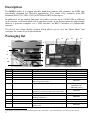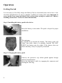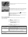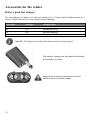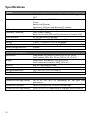
1
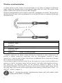
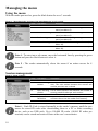
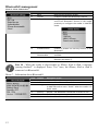
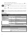
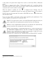
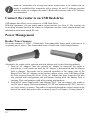
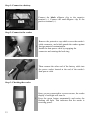
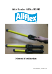
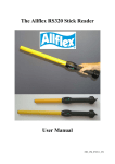
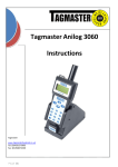
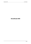
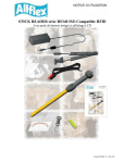
RS420
Portable stick reader
USER MANUAL
Version 1.9
Description
The RS420 reader is a rugged portable hand-held scanner and telemeter for RFID tags
specifically designed for livestock applications. The reader fully complies with ISO
standards ISO11784 / ISO11785 for FDX-B and HDX technologies.
In addition to its tag reading functions, the reader can store up to 100,000 IDs in different
work sessions, each associated with a time/date stamp, in its internal memory and transmit
them to a personal computer via a USB interface, an RS232 interface or a Bluetooth®
interface.
The device has a large display window which allows you to view the “Main Menu” and
configure the reader to your specifications.
Packaging list
11
12
13
1
6
2
7
3
8
4
9
10
5
Item
1
2
3
4
5
features
Cardboard
Reader
IEC cable
CD-ROM
Data-Power Cable
6
External Power Adapter
7
USB flash drive adapter
8
9
User Manual
Ear Tags
10 & 12
11
13
Rechargeable Li-Ion battery
External Power Adapter
Plastic case
1
Description
Part Number
Used to transport the reader
E01VE025
Supply cable to power the external adapter
Support for user manual and reader datasheets
E88VE018
Conveys external power to reader and serial
E88VE017
data to and from reader.
Powers the reader and charges the battery
E88VE016 (North-America)
E88VE028 (UK)
E88VE020 (other)
Allows the user to connect an USB stick to
E88VE015
upload or to download data to or from reader.
E88VE014
2 ear tags to demonstrate and test FDX and HDX
E88VE012
reading capabilities.
Supplies the reader. Adds expected battery life
E88VE013
Powers the external fast charger
E94VE00x1
Use to transport the reader and accessory in a
E88VE027
robust case.
E94VE001 = Europe (EU) except United-Kingdom (UK), E94VE002 = UK and E94VE003 = World except EU and UK
2
Figure 1 - Reader features and user interface.
Table 1 – Reader features and description of use
Item Feature
Description of use
1
2
3
4
5
6
7
8
9
10
11
12
3
Antenna
Fiberglass Tube Enclosure
Audible beeper
Emits activation signal and receives transponder signal.
Rugged and watertight enclosure.
Beeps once on first transponder reading and 2 short beeps for
repeat.
Large graphical readout with Displays information about current reader status.
backlight
Green indicator
Illuminates whenever a transponder data has been stored.
Red indicator
Illuminates whenever antenna is emitting activation signal.
black MENU button
Navigates in the reader menu to manage or to configure it.
green READ button
Applies power and causes activation signal to be emitted for reading
transponder
Vibrator
Vibrates once on first transponder reading and short vibrates for
repeat.
Handle grip
Rubber anti-slip griping surface
Cable connector
Electrical interface for attaching Data/Power cable or USB stick
adapter.
Bluetooth®
Wireless interface to communicate data to and from reader (not
pictured)
Operation
Getting Started
It is necessary to first fully charge the Battery Pack as described below and to have a few
electronic identification ear tags or implants available for testing. It is very important to
carry out the three steps described in this section before using the reader (see “Battery
handling instructions” section for more information)
Step 1: Installing the battery pack in the device.
1
Insert the battery in the reader. The pack is keyed for proper
installation.
The stationary
key should be up towards the display. The battery pack will
2 “snap” into place when it is properly inserted. DO NOT
FORCE the battery into the reader. If the battery does not
insert smoothly, verify it is properly orientated.
Step 2: Charging the battery pack.
Unscrew the protective cap which guards against foreign
material contamination.
1
Insert the data-power cable by engaging the connector and
rotating the lock-ring.
4
2
Plug the power cord into the cable socket located at the end of
the data-power cable.
Plug the adapter into a power outlet. The icon of the battery
3 level indicates that the battery pack is in charge (the level bars
flash inside the icon) and gives the battery charge level.
The icon of the battery level will be
when charging has
finished. Charging takes approx. 3 hours.
4 Remove the power cord.
Unplug the adapter from the power outlet, and remove the
data-power cable inserted in the reader.
Power on instructions
Press the green button on the reader handle to power on the reader. The main screen will
appear on the display:
Item Feature
1
Battery level
2
3
4
5
Description of use
The battery level shows the fully charged level as well as the
charge level during the charge mode.
USB connection Appears when the reader is connected to a computer via USB port.
NOTE: The reading mode is disabled if there is no battery and no
external power supply. Therefore it is not possible to read a
transponder although the other functions are fully active.
Current number Number of read and saved ID codes in the current session.
of ID codes
Clock
Clock time in 24 hour mode.
5
6
7
Bluetooth
connection
Reader name
Check the Bluetooth® status and connection (see section “
Bluetooth® management” for more details).
Displays the reader name. It appears only upon power on and until
a tag is read.
Number of ID Total number of read and saved ID codes in all recorded sessions.
codes
Note 1 - Once activated, the reader will remain activated for 5 minutes by default,
if it is powered only by its battery pack.
Read Range Performance
Figure 2 illustrates the reading zone of the reader, within which tags can be successfully
detected and read. Optimum read distance occurs depending upon the orientation of the tag.
Tags and implant read best when positioned as shown below.
Figure 2 - Optimum Read Distance Tag Orientation
Item
1
2
3
4
5
6
Legend
Reading zone
RFID Ear tag
RFID Implant
Best orientation
Antenna
Reader
Comments
Area in which the ear tags and the implants can be read.
Best orientation of the ear tags regarding the reader antenna
-
Typical read distances will vary when reading different types of ear tags, in the optimum tag
orientation at the end of the reader (as shown in Figure 2), the reader will read up to 42cm
depending tag type and orientation.
6
Power off instructions
The reader can be powered off by simultaneously depressing BOTH buttons for
approximately 3 seconds
Reading an RFID Transponder
Scanning animals
Place the device near the animal identification tag to be read, then press the green button in
order to activate the reading mode. The screen backlight switches on and the red light will be
flashing.
During the reading mode, move the reader along the animal to scan the transponder ID. The
reading mode remains activated during a programmed duration. If the green button is held
down, the reading mode remains activated. If the device is programmed in continuous
reading mode, the reading mode remains indefinitely activated until you press the green
button a second time.
The following picture shows the result of a successful reading session:
Item Feature
1
Transponder type
2
3
4
7
Description of use
ISO standard 11784/5 has approved 2 technologies for animal
identification: FDX-B and HDX. When the reader displays the
word “IND” as transponder type, it means that its transponder
is not coded for animals.
Country code / The country code is according the ISO 3166 and ISO 11784/5 in
Manufacturer
numeric or in alpha coding. Manufacturer code is according to
code
ICAR assignment.
First digits of ID First digits of the identify code is according the ISO 11784/5.
code
Last digits of ID Last digits of the identify code is according the ISO 11784/5. The
code
user can select the number of last bold digits (between 3 and 8
digits).
When a new EID transponder is successfully read, the green light flashes and the reader
stores the ID code in its internal memory after its first reading (and if the option “duplicate
search” is activated) with the current date and time (if the option is activated).
The number of read ID codes in the current session is increased.
The buzzer and the vibrator will sound and/or vibrate with every scan.
Note 2 –The ‘Date and Time Stamp’, and the sound/vibration features are options
that can be turned on or off according to your specific applications.
Each time a tag is scanned, the identification code is transmitted automatically via the USB
cable, the RS232 cable, or Bluetooth®.
Tips for efficient reading
Tag reader efficiency is often linked with reading distance. The device's read distance
performance is affected by the following factors:
1. Transponder orientation: to obtain maximum reading distance, the axes of the
transponder and reader antenna coils must be optimally orientated as shown in Figure
2.
2. Transponder quality: Each transponder manufacturer uses their own unique
manufacturing process. Consequently, it is normal to find that many common
transponders from different manufacturers have different read range performance
levels.
3. Animal movement: If the animal moves too quickly, the transponder may not be
located in the read zone long enough for the ID code information to be obtained.
4. Transponder type: HDX and FDX-B transponders generally have similar reading
distances, but tag manufacturers and environmental factors such as RF interferences
may affect overall tag performances.
5. Nearby metal objects: Metal objects located near a transponder or reader may
attenuate and distort the magnetic fields generated in the RFID systems therefore,
reducing the reading distance. An example, an ear tag against a squeeze chute
significantly reduces the read distance.
6. Electrical noise interference: The operating principle of RFID transponders and
readers is based on electromagnetic signals. Other electromagnetic phenomena, such
as radiated electrical noise from other RFID tag readers, or computer screens may
interfere with RFID signal transmission and reception, therefore, reducing the read
distance.
7. Transponder/reader interference: Several transponders in the reception range of the
reader, or other readers that emit excitation energy close by may adversely affect
reader performance or even prevent the reader from operating.
8. Discharged battery pack: As the battery pack discharges, the power available to
activate the field becomes weaker, which in turn reduces the read range field.
8
Wireless synchronization
A reader which is in the vicinity of a second reader is very likely to transmit its activation
signal during the listening pause of the second reader and vice versa. The result is that
neither reader will be able to receive the HDX telegram.
Wireless synchronization can be used to control the coordination of readers. The proviso is
that the electrical noise in the environment is low and the RFI noise is constant, for the type
of readers in use.
Item
1
2
3
4
Legend
Activation signal
of reader 1
Reader 1
Activation signal
from reader 1
Reader 2
Comments
reader 1 in transmitting mode.
reader 2 in listening mode.
“A mobile transceiver by nature cannot directly be connected to other transceivers. To
prevent a mobile transceiver interfering with the interrogation protocol of other
transceivers, it must be able to detect the presence of additional active transceivers through
the reception of activation signals.
If no activation signal is detected within 30 ms, the transceiver is out of reach of other active
transceivers and its activation signal will not interfere with other interrogation processes.
The transceiver can therefore safety use the protocols defined in clause 6 of this
International Standard. If the mobile transceiver detects an activation signal it must wait for
the rising edge of the next activation signal and activate during a fixed period of 50ms.” (cf.
ISO1185 – Annex C chapter 3)
Note 3 – Activate the wireless synchronization feature only with readers which
comply with the ISO11785 timings.
9
Managing the menu
Using the menu
With the reader powered on, press the black button for over 3 seconds.
Menu 1 – Menu listed after pressing of the black button for over 3 seconds.
Item
1
2
Sub-Menu
Back
Session
3
Bluetooth settings
4
Read settings
5
General settings
6
Reader information
Definition
Return to the main screen
Enter into the session management submenu (see Menu 2)
Enter into the Bluetooth management submenu (see Menu 6)
Enter into the reading management submenu (see Menu 8)
Enter into the device settings sub-menu (see
Menu 14).
Gives information about the reader (see
Menu 19).
Note 4 – To enter into a sub-menu, move the horizontal lines by pressing the green
button and press the black button to select it.
Note 5 - The reader automatically closes the menu if no action occurs for 8
seconds.
Session management
Menu 2 - Menu “session”
Item
1
2
Sub-Menu
Back
New working
session
3
Open working
session
Export session
Import from
flash drive
Delete session
4
5
6
Definition
Return to the previous screen
Create a new work session after validation by the
user. This new session becomes the current one
and the previous one is closed.
List all stored sessions and indicates the number of
existing saved ID codes per each session.
Enter into the export sub-menu.
Import sessions from flash drive (memory stick)
and store them into the reader flash memory.
Enter into the delete sub-menu
Note 6 – Each ID Code is stored internally in the reader’s memory until the user
erases the stored ID codes after downloading them to a PC or other recording
device, such as an USB stick. Up to 100,000 ID codes (10,000 ID codes per
sessions) can be stored and retrieved later at the user’s convenience.
10
Note 7 – If enabled, the reader provides a time and date stamp for each ID number
stored.
The user can enable the date and time through a communication interface (USB,
Serial, or Bluetooth® port) and the software program.
Menu 3 - Menu “export session”
Item
1
2
3
Sub-Menu
Back
Current
session
Select session
4
All sessions
Definition
Return to the previous screen
Open the Menu 4 to select the channel to export the current session.
List the stored sessions and once a session is selected, open the Menu 4 to select
the channel to export the selected session.
Open the link sub-menu to select the channel to export all sessions.
Menu 4 - List of channels to export the session(s):
Item
1
2
3
4
5
Sub-Menu
Back
Bluetooth
USB flash drive
USB link
Serial link
Definition
Return to the previous screen
Send session(s) via the Bluetooth link
Store the session(s) on flash drive (memory stick) (see Note 9)
Send session(s) via the USB link
Send session(s) via the Serial link
Note 8 – Connect your flash drive (memory stick), establish an USB connection, a
serial connection or a Bluetooth® connection before to select the session
importation or the session exportation.
Note 9 – Connect your flash drive (memory stick) before exporting the session
otherwise the message “No drive detected” is displayed, check that the drive is
well-connected then please retry or cancel.
Menu 5 – Menu “delete session”
Item
1
2
Sub-Menu
Back
Select session
3
All sessions
11
Definition
Return to the previous screen
List the stored sessions, and once a session is selected, it is deleted after
confirmation.
Erase all stored sessions after confirmation.
Bluetooth® management
Menu 6 - Menu “Bluetooth®”
Item
1
2
3
Sub-Menu
Back
On/Off
Select device
Definition
Return to the previous screen
Enable or Disable the Bluetooth® feature.
Configure the reader in SLAVE mode or scan
and list all Bluetooth® devices in the reader
proximity to configure the reader in MASTER
mode.
4
Authentication
5
iPhone
Discoverable
About
Enable or disable the security feature of the
Bluetooth®
Make the reader discoverable by iPhone, iPad
and iPod.
Provide information about the Bluetooth®
features (see Menu 7).
6
Note 10 – When the reader is discoverable by iPhone, iPad or iPod, a message
“pairing finished?” is displayed. Press “Yes” once, the iPhone, iPad or iPod is
connected via Bluetooth®.
Menu 7 – Information about Bluetooth®
12
Item
1
2
3
Feature
Name
Addr
Pairing
4
5
6
Security
PIN
Version
Description of use
Name of the reader.
Address of the Bluetooth® module.
“Bluetooth® address of the device” when the reader is
in MASTER mode or term “SLAVE” when the reader is in
SLAVE mode.
On/Off – the Bluetooth® connection is secure or not.
Pin code
Version of the Bluetooth® stack.
Note 11 – Understanding the Bluetooth® icon:
When the Bluetooth® module is enabled but not connected, an icon
displayed and is blinking.
is
If the icon
mode.
doesn’t blink, that means the device is connected in SLAVE
If the icon
mode.
is displayed, a connection has been established in MASTER
Note 12 – 1 beep is emitted and 1 message is displayed when the Bluetooth®
connection is established and 3 beeps are emitted when the connection is removed.
Read settings
Menu 8 - Menu “Read settings”
Item
1
2
Sub-Menu
Back
Read time
Definition
Return to the previous screen
Manage the scanning time of reading (3s, 5s, 10s
or continuously scanning)
Tag
storage Manage the storage of read tag (no storage, on
mode
read and on read but no duplicated in the
memory)
Comparison and Manage comparison and alerts regarding read
Alerts
tags (see Menu 12).
Counter mode
Manage the counters displayed on main screen
RFID
Power Manage the power consumption of the device
Mode
(see
Menu 10)
Temperature
Manage the temperature detection. This option
is useful with Bio-Thermo® implants.
3
4
5
6
7
Menu 9 - Menu “Counter mode”
Item
1
2
Sub-Menu
Back
Session | Total
3
Session | Unique tags
13
Definition
Return to the previous screen
1 counter for all IDs stored in the current session and 1 counter for all
IDs saved in memory (max. 9999)
1 counter for all IDs stored in the current session and 1 counter for all
unique IDs stored in memory (max. 1000). The tag storage mode is
automatically changed to “ON READ” (referred to item 3 in menu
above).
Menu 10 - Menu “RFID power mode”
Item
1
2
3
Sub-Menu
Back
Save power
Full power
Definition
Return to the previous screen
Puts the device in low power consumption with shorter reading distances.
Puts the device in high power consumption
Menu 11 - Menu “Temperature”
Item
1
2
3
Sub-Menu
Back
Disabled
Enabled
Definition
Return to the previous screen
Disable the temperature measurement
Enable the temperature measurement
Note 13 – When the reader is in low consumption, the reading distances are
reduced.
Menu 12 - Menu “Comparison and Alerts”
Item
1
2
3
4
SubMenu
Back
Select
compare
Disable
compare
Alerts
Definition
Return to the previous screen
List all sessions saved inside the reader and select the
comparison session used to compare the read ID
codes.
Disable the comparison.
Enter into the menu “alerts” (see Menu 13).
Menu 13 - Menu “Alerts”
Item
1
2
3
4
5
SubMenu
Back
Disabled
On animal
found
On animal
not found
From
compare
session
Definition
Return to the previous screen
Disable the alert management.
Produce an alert signal when the read ID code is found
in the comparison session.
Produce an alert signal when the read ID code is NOT
found in the comparison session.
Produce an alert message if the read ID is tagged with
an alert within the compare session.
Note 14 – When a tag is read and compared successfully to an ID code stored in a
selected comparison session, supplementary information stored in the comparison
session, can be displayed on the reader’s screen (ex: visual id code, supplementary
data…)
14
General settings
Menu 14 - Menu “general settings”
Item
1
2
3
4
5
6
7
Sub-Menu
Definition
Back
Return to the previous screen
Load profiles Allow to recall profiles saved in the reader. By
default, the factory settings can be reloaded.
Quick action Attribute a second feature to the black button (see
Menu 15).
Vibrator
Manage the vibrator (see
Menu 16).
Buzzer
Manage the audible beeper (see Menu 17).
Protocol
Select the protocol used by the communication
interfaces (see Menu 18).
Language
Select the language used by the device (English,
French or Spanish).
Note 15 – A profile corresponds to the current settings of the reader which can be
dedicated to a custom use. The user can save up to 4 profiles.
Menu 15 - Menu “quick action”
Item
1
2
3
4
5
SubMenu
Back
Disabled
Enter
menu
New
session
Re-send
last tag
Definition
Return to the previous screen
No feature attributed to the black button
Fast access to the menu.
Fast creation of a new session.
Last read tag is re-sent on the communication
interfaces.
Note 16 – A quick action is a second feature attributed to the black button. The
reader performs the selected action after a short keystroke of the black button.
Note 17 – If the user holds the black button for over 3 seconds, the device displays
the menu and the quick action is not performed.
Note 18 – The symbol “>” is in front of the current selected option.
15
Menu 16 Menu “vibrator”
Item
1
2
3
Sub-Menu
Back
Disabled
Enabled
Definition
Return to the previous screen
Disable the vibrator
Enable the vibrator
Note 19
- A short vibration indicates that the reader has previously read the tag during
the current session.
- A vibration of medium-duration means that the reader has read a new tag
which has NOT been previously read during the current session.
- A long vibration means that there is an alert regarding the tag which has
been read.
Menu 17 - Menu “buzzer”
Item
1
2
3
Sub-Menu
Back
Disabled
Enabled
Definition
Return to the previous screen
Disable the audible beeper.
Enable the audible beeper.
Note 20
- A short beep indicates that the reader has switched on or that the Bluetooth®
connection is established.
- Two short beeps mean that the reader has previously read the tag during the
current session.
- Three short beeps mean that the Bluetooth® connection is removed.
- A beep of medium-duration means that the reader has read a new tag which
has NOT been previously read during the current session
- A long beep means that there is an alert regarding the tag which has been
read.
Menu 18 – Menu “protocol”
Item
1
2
3
SubMenu
Back
Standard
protocol
Allflex
RS320 /
RS340
Definition
Return to the previous screen
Select the standard protocol defined for this reader
(see specifications Protocol_Document_V1.0).
Select the protocol used by ALLFLEX’S readers RS320
and RS340.
Note 21 – All commands of ALLFLEX’S reader are implemented but all
functionalities are not implemented (see specifications Protocol_Document_V1.0).
16
About the reader
Menu 19 - Menu “Reader information”
Item
1
2
3
4
5
Feature
FW
HW
Memory
used
Files used
Batt
Description of use
Indicates the firmware version of the reader
Indicates the hardware version of the reader
Indicates the percentage of the memory used.
Indicates the number of files saved in the reader.
Indicates the battery charge level in percentage.
Connect the reader to a PC
This section is meant to describe how to connect the reader to hand held computer (PDA) or
to a personal computer (PC). The device can be connected to a PC in 3 ways: a wired USB
connection, a wired RS-232 connection, or by a wireless Bluetooth® connection.
Using USB interface
The USB port allows the device to send and receive data via a USB connection.
To establish a USB connection, simply connect the reader to a PC or a PDA with the datapower cable.
Remove the protective cap which covers the reader’s cable
connector, and guards the reader against foreign material
1 contamination.
Install the data-power cable by engaging it into the connector
and rotating the lock-ring.
2 Plug the USB extension into a USB port on your computer.
17
Note 22 – Once the USB cable is connected, the reader is automatically powered
on and it will remain activated until the cable is disconnected. The reader will be
able to read a tag if a sufficiently charged battery is inserted. With a depleted
battery, the reader will not be able to read a tag, but will remain on and can only
communicate with computer.
When connecting to a PDA or a PC, you may need to install specific drivers supplied by
manufacturer. When connecting to a Windows PC, the operating systems start the Device
Manager (more details provided by the manufacturer on the CDROM).
Using serial interface
The serial port allows the device to send and receive data via an RS-232 connection.
To establish a USB connection, simply connect the reader with a PC or a PDA with the datapower cable.
The RS232 serial interface comprises a 3-wire arrangement with a DB9F connector, and
consists of transmit (TxD/pin 2), receive (RxD/pin 3), and ground (GND/pin 5). This
interface is factory configured with the default settings of 9600 bits/second, no parity, 8
bits/1 word, and 1 stop bit (“9600N81”). These parameters can be changed from PC
software.
Serial output data appears on the device’s TxD/pin 2 connection in ASCII format.
Note 23 - The RS232 interface is wired as a DCE (data communications
equipment) type that connects directly to the serial port of a PC or any other device
that is designated as a DTE (data terminal equipment) type. When the device is
connected to other equipment that is wired as DCE (such as a PDA), a “null
modem” adapter is required in order to properly cross-wire transmit and receive
signals so that communications can occur.
Note 24 - The reader’s serial data connection can be extended using a standard
DB9M to DB9F extension cable. Extensions longer than 20 meters (~65 feet) are
not recommended for data. Extensions longer that 2 meters (~6 feet) are not
recommended for data and power.
Using Bluetooth® interface
Bluetooth® works on a premise that one end of the communication will be a MASTER and
the other a SLAVE. The MASTER initiates communications and looks for a SLAVE device
to connect to. When the reader is in SLAVE mode it can be seen by other devices such as a
PC or PDA. PDAs and computers usually behave as MASTERS with the reader configured
as a SLAVE device.
When the reader is configured as a MASTER it cannot be seen by other devices other than
the device it is paired to. Readers are typically used in a MASTER mode configuration when
18
it only needs to be paired with a single device such as a scale head, PDA, or Bluetooth
printer
The reader is equipped with a Class 12 Bluetooth® module and is compliant with the
Bluetooth® Serial Port Profile (SPP) and the Apple’s iPod® Accessory Protocol (iAP). The
connection can be in slave mode or in master mode.
When the module is enabled, the icon
is displayed and is blinking. Once the
communication is established between the reader and another device, if the reader is
SLAVE, the icon is the same and if the reader is MASTER, the icon is
the icon stops to blink.
. In both cases,
If you are using a PDA, it will require software (Not supplied by the manufacturer). Your
software supplier will explain how to connect the PDA.
Note 25 - We advise that to achieve successful Bluetooth® connection with your
reader, simply follow the implementation methods listed (see the following).
Note 26 - If these implementation methods are not followed, the connection may
become inconsistent, thus causing other reader related errors.
Note 27 - When Windows 7 installs Bluetooth® drivers, it will not find the driver
for "Bluetooth® Peripheral Device" but this is normal (see picture below).
Windows cannot install this driver because it corresponds to Apple iAP service
needed to connect with iOS devices (iPhone, iPad).
For reader to PC connection, only "Standard Serial over Bluetooth link" is needed.
2
Operating distance of communication is around 100 m (330 ft).
19
Bluetooth® – Known Successful Methods
There are 2 scenarios to correctly implement the Bluetooth® connection. They are as
follows:
1. Reader to a Bluetooth® adapter connected to a PC, or to a Bluetooth® enabled PC or
PDA.
2. Reader to a Bluetooth® adapter connected to a scale head, or to a Bluetooth® enabled
device, such as scale head or printer.
These options are discussed in further details below.
Reader to a Bluetooth® adapter connected to a PC, or to a Bluetooth®
enabled PC or PDA
This scenario requires that a process called « Pairing » be undertaken. On the reader, go to
the menu “Bluetooth”, and then select “slave” in the sub-menu “select device” to remove the
previous pairing and allow the reader to return to SLAVE mode.
Start your PC Bluetooth® Manager
program or PDA Bluetooth®
services,
Depending on which Bluetooth
device your PC is using the
Bluetooth Manager may vary in how
it pairs a device. As a general rule the
program should have the option to
“Add a Device” or “Discover a
Device”.
With the reader turned on, select one
of these options. The Bluetooth®
program should open a window
within one minute showing all
Bluetooth enabled devices in the
area. Click on the device (the reader)
you want to connect to and follow the
steps provided by the program.
20
READER NAME
Passkey enabled
The program may ask you to provide
a “Pass Key” for the device. As noted
in the following example, select the
option “Let me choose my own
passkey”. The default passkey for the
reader is: 1234
The program will assign 2 communication ports for the reader. Most applications will use the
outgoing port. Make note of this port number for use when connecting to a software program
If this fails use the following links, search the reader in the peripheral list and connect it. You
have to add an outgoing port that makes a connection to the device. Follow the steps
described in the links below.
For Windows XP: http://support.microsoft.com/kb/883259/en-us
For Windows 7: http://windows.microsoft.com/enUS/windows7/Connect-to-Bluetooth-and-other-wireless-ornetwork-devices
Note 28 - Sometimes, a PIN code is required to connect the reader to the PC,
PDA… In such case, the PIN code to use is 1234.
Reader to a Bluetooth® adapter connected to a scale head, or to a
Bluetooth® enabled device, such as scale head or printer.
This scenario requires that the reader lists the Bluetooth® peripherals. Go to the menu
“Bluetooth”, then the sub-menu “Search device” which launches the Bluetooth® scanning.
The device you want to connect to will be displayed on the reader. Use the green button to
scroll to the desired device. Select the device by depressing the black button on the reader.
The reader will now connect in “slave’ mode.
To connect the reader in ‘Master” mode the reader will need to be configured using the Tag
Manager program3. In the “Reader setup” section of the Tag Manager Program, the user can
enter the 12 character address of the device they want to connect to. Once this is done the
reader will be in Master mode when it connects to that device.
3
Detailed instructions about EID Tag Manager are documented in a Help file.
21
Note 29 - Sometimes, the security and check features have to be disabled on the
reader to established the connection with a printer. So use PC software provided
with the reader, to configure the reader’s Bluetooth® security (refer to PC software
documentation).
Connect the reader to an USB flash drive
USB adapter that allows you to connect to a USB Flash Drive.
With this equipment, you can import and/or export sessions (see Note 9). The sessions can
be working sessions stored in the reader or comparison sessions which contain details and
information about each animal ID code.
Power Management
Reader Power Sources
The reader contains a 7.4VDC – 2600mAh Li-Ion rechargeable battery pack, which serves as
its primary power source. This feature adds hours of scans with a fully charged battery.
Alternately, the reader can be powered and used indoors only by the following methods:
1. From its AC Adapter. Once the external AC adapter is connected, the reader is
powered-up, it will remain on until the AC adapter is disconnected and the Battery
Pack is charged. The reader can be powered regardless of the charge state of the
Battery Pack. The AC Adapter can be used as a power source even if the Battery Pack
has been removed from the device. If the AC Adapter has been connected, the user
may proceed with configuration and performance testing while the Battery Pack is
charging. This configuration could affect reading performances.
2. From its DC power supply cable with alligator clips4: You can connect your reader to
any DC power supply (between minimum 12V DC and maximum 28V DC) such as a
car, truck, tractor, or battery. The reader is connected through the socket located on the
back of the reader data-power cable as shown in step 2 (see chapter “Getting Started”).
4
Not proposed for sale in Europe
22
Step 1: Connect to a battery
Connect the black alligator clip to the negative
1 terminal (-). Connect the red alligator clip to the
positive terminal (+).
Step 2: Connect to the reader
Remove the protective cap which covers the reader’s
cable connector, and which guards the reader against
1 foreign material contamination.
Install the data-power cable by engaging the
connector and rotating the lock-ring.
Then connect the other end of the battery cable into
2 the power socket located at the end of the reader’s
data-power cable
Step 3: Checking the reader
Once you are connected to a power source, the reader
display’s backlight will turn on.
1 Press the green button momentarily and notice the
flashing red light. This indicates that the reader is
receiving power.
23
At the top of the screen, the icon of the battery level shows the discharge level as well as the
charge level during the charge mode.
Display
Summary
Good.
Quite good.
Slightly depleted, but sufficient
Depleted. Recharge the battery.
“LOW BATTERY”
Depleted. Recharge the battery.
Reader power instructions
Note 30 - The reader is designed to operate only with the Battery Pack provided.
The reader will not operate with individual battery cells of either disposable or
rechargeable variety.
CAUTION
RISK OF EXPLOSION IF BATTERY IS REPLACED BY AN INCORRECT
TYPE. DISPOSE OF USED BATTERIES ACCORDING TO THE
INSTRUCTIONS.
Note 31 - Do not use this reader near water when connected to the AC/DC adapter.
Note 32 - Do not install near any heat sources such as radiators, heat registers,
stoves, or other apparatus that produce heat.
Note 33 - Do not charge the battery pack from AC main sources during electrical
storms or when unused for long periods of time.
Note 34 - The reader is protected for reverse polarity connections.
Battery handling instructions
Please read and follow the handling instructions for the battery before use. Improper use of
the battery may cause heat, fire, rupture, and damage or capacity deterioration of the battery.
24
Caution
1. Do not use or leave the battery in high heat environments (for example, at strong direct
sunlight or in a vehicle in extremely hot weather). Otherwise, it can overheat, ignite, or
battery performance will be degraded, thus shortening its service life.
2. Do not use it in a location where static electricity is rich, otherwise, the safety devices
may be damaged, causing a harmful situation.
3. In case the electrolyte gets into the eyes due to the leakage of battery, do not rub the eyes!
Rinse the eyes with clean running water, and seek medical attention immediately.
Otherwise, it may injure eyes or cause a loss of sight.
4. If the battery gives off an odour, generates heat, becomes discoloured or deformed, or in
any way appear abnormal during use, recharging or storage, immediately remove it from
the device and place it in a contained vessel such as a metal box.
5. Power or charge failure may occur due to the poor connection between the battery and the
reader if the terminals are dirty or corroded.
6. In case the battery terminals are corroded, clean the terminals with a dry cloth before use.
7. Be aware that discarded batteries may cause fire. Tape the battery terminals to insulate
them before disposal.
Warning
1.
2.
3.
4.
5.
6.
Do not immerse the battery in water.
Keep the battery in a cool dry environment during storage periods.
Do not use or leave the battery near a heat source such as fire or heater.
When recharging, use only the battery charger from manufacturer.
The battery charge should be realized indoors at a temperature between 0° and +45°C.
Do not let the battery terminals (+ and -) contact any metal (like ammunition, coins, metal
necklace or hairpins). When carried or stored together this may cause short-circuit, or
severe bodily damage.
7. Do not strike or puncture the battery with other objects, or use in any way other than its
intended use.
8. Do not disassemble or alter the battery.
Notice
1. The battery should only be charged and discharged using the proper charger supplied by
the manufacturer.
2. Do not replace the battery with other manufacturer's batteries, or different types and /or
models of batteries such as dry batteries, nickel-metal hydride batteries, or nickelcadmium batteries, or a combination of old and new lithium batteries together.
3. Do not leave the battery in a charger or equipment if it generates an odour and/or heat,
changes color and/or shape, leaks electrolyte, or cause any other abnormality.
4. Do not discharge the battery continuously when it is not charged.
5. It is necessary first to fully charge the Battery Pack as described in the section “Getting
Started” before using the reader
25
Accessories for the reader
Battery pack fast charger
The fast charger for indoors use only can charge up to 2 battery packs simultaneously in 3
hours. A light indicates the status of each battery charging.
Green light
Off
Off
On
On
Red light
Off
On
Off
On
Charger status
Not Charging – Standby or Shutdown
Bad-Battery fault
Normal Charging
Temperature fault
Note 35 – The lights switch off when the batteries are fully charged.
The battery charger can be placed horizontally
or vertically on a table.
Make sure the battery orientation is correct
before insertion into the charger.
26
Plastic Carry Case
Durable Plastic Carry Case is available as an optional extra or is included in the “Premium
Kit” Package.
27
Specifications
General
Norms:
User interface:
USB interface:
Bluetooth® interface:
Serial interface
Memory:
Battery:
Date/Time autonomy:
Battery charge duration:
Mechanical and physical
Dimensions:
Weight:
Material
Operating temperature
Storage temperature
Humidity:
Reading
Distance for ear tags (cattle):
Distance for implants:
Distance for ear tags (sheep):
28
ISO 11784 and full ISO 11785 for FDX-B and HDX tags
IP67
Graphical display 128x128 dots
2 keys
Buzzer and Vibrator
Serial port, USB port and Bluetooth® module
CDC class (Serial emulation) and HID class.
Class 1 (up to 100m)
Serial Port Profile (SPP) and iPod Accessory Protocol (iAP)
RS-232 (9600N81 by default)
>100,000 animal IDs (10,000 animal IDs per session)
7.4VDC – 2600mAh Li-Ion rechargeable.
1 month without reader usage @ 20°C
3 hours
Long reader: 670 x 60 x 70 mm (26.4 x 2.4 x 2.8 in)
Short reader: 530 x 60 x 70 mm (20.9 x 2.4 x 2.8 in)
Long reader with battery: 830 g (29.3 oz)
Short reader with battery: 810 g (28.6 oz)
ABS-PC and fiberglass tube
-20°C to +55°C (+4°F to +131°F)
-30°C to +70°C (-22°F to +158°F)
80%
Up to 42 cm (16.5 in) depending on tag type and
orientation.
Up to 20 cm (8 in) for 12-mm FDX-B ear tags.
Up to 30 cm (12 in) depending on tag type and orientation.
Reader physical integrity
The device has been built from rugged and durable materials to withstand use in harsh
environments for long periods of time. However, the reader contains electronic components
that can be damaged if they are deliberately exposed to extreme abuse. This damage can
adversely affect, or stop the reader's operation. The user must avoid deliberately striking
other surfaces and objects with the device. Damage that results from such handling is not
covered by the warranty described below.
Limited Product Warranty
Manufacturer guarantees this product against all defects due to faulty materials or
workmanship for a period of one year following the date of purchase. The warranty does not
apply to any damage resulting from an accident, misuse, modification or an application other
than that described in this manual and for which the device was designed.
If the product develops a malfunction during the warranty period, manufacturer will repair or
replace it free of charge. The cost of shipment is at the customer's expense, whereas return
shipment is paid by manufacturer.
Refer all servicing to qualified service personnel. Servicing is required when the reader has
been damaged in any way, such as power-supply cord or plug is damaged, liquid has been
spilled or objects have fallen into the apparatus, the apparatus has been exposed to rain or
moisture, does not operate normally, or has been dropped.
Regulatory information
USA-Federal Communications Commission (FCC)
This device complies with part 15 of FCC rules. Operation is subject to the following two
conditions: (1) This device may not cause interference, and (2) this device must accept any
interference, including interference that may cause undesired operation of the device.
This equipment has been tested and found to comply with the limits for a Class B digital
device, pursuant to Part 15 of FCC Rules. These limits are designed to provide reasonable
protection against harmful interference in a residential installation.
This equipment generates, uses, and can radiate radio frequency energy. If not installed and
used in accordance with the instructions, it may cause harmful interference to radio
communications. However, there is no guarantee that interference will not occur in a
particular installation.
If this equipment does cause harmful interference to radio or television reception, which can
be determined by tuning the equipment off and on, the user is encouraged to try and correct
the interference by one or more of the following measures:
Reorient or relocate the receiving antenna.
Increase the distance between the equipment and the receiver.
29
Connect the equipment to outlet on a circuit different from that to which the receiver is
connected.
Consult the dealer or an experienced radio/TV technician for help.
The user must be at 20 cm of the reader antennas.
Notice to Consumers:
Any changes or modifications not expressly approved by the party responsible for
compliance could void the user’s authority to operate the equipment.
Canada – Industry Canada (IC)
This device complies with RSS 210 of Industry Canada. Operation is subject to the following
two conditions: (1) This device may not cause interference, and (2) this device must accept
any interference, including interference that may cause undesired operation of this device.”
L ‘ utilisation de ce dispositif est autorisée seulement aux conditions suivantes : (1) Il ne doit
pas produire d’interférence et (2) l’utilisateur du dispositif doit être prêt à accepter toute
interférence radioélectrique reçu, même si celle-ci est susceptible de compromettre le
fonctionnement du dispositif.
Avis aux consommateurs:
Toutes modifications non expressément approuvées par la partie responsable de la
conformité peuvent annuler le droit de l'utilisateur à utiliser cet équipement.
L’utilisateur doit se tenir à 20 cm des antennes du lecteur.
Apple - Legal Notice
iPod® is a trademark of Apple Inc., registered in the U.S. and other countries.
iPhone® is a trademark of Apple Inc., registered in the U.S. and other countries.
iPad® is a trademark of Apple Inc., registered in the U.S. and other countries.
“Made for iPod,” “Made for iPhone,” and “Made for iPad” mean that an electronic accessory
has been designed to connect specifically to iPod ®, iPhone®, or iPad®, respectively, and has
been certified by the developer to meet Apple performance standards.
Apple is not responsible for the operation of this device or its compliance with safety and
regulatory standards.
Please note that the use of this accessory with iPod ®, iPhone®, or iPad® may affect wireless
performance.
30
Regulatory Compliance
ISO 11784 & 11785
This device complies with the standards set forward by the International Standardization
Organization. Specifically with standards:
11784: Radio frequency identification of animals -- Code Structure
11785: Radio frequency identification of animals -- Technical Concept.
FCC NQY-30002
IC 4246A-30002
CE Marking
Trademark Notices
Bluetooth® is a registered trademark of Bluetooth SIG, Inc.
31
Allflex Offices
Allflex UK Ltd.
Unit 6 - 8 Galalaw Business Park
HAWICK
United Kingdom
TD9 8PZ
Phone: 44 (0) 1450 364120
Fax: 44 (0) 1450 364121
www.allflex.co.uk
Allflex USA, Inc.
P.O. Box 612266
2805 East 14th Street
Dallas Ft. Worth Airport, Texas 75261-2266
United States of America
(800) 989-TAGS [8247]
(972) 456-3686
(972) 456-3882/FAX
www.allflexusa.com
SISTEMAS DE IDENTIFICAÇAO ANIMAL LTDA
Rua Dona Francisca 8300 Distrito Industrial
Bloco B – Módulos 7 e 8
89.239-270 JOINVILLE
SC BRASIL
Tel : +55 47 451 05 00
BEIJING ALLFLEX PLASTIC PRODUCTS
SAN TAI SHAN - XIAO HONG MEN
CHAO YANG DISTRICT
PO BOX 5206
BEIJING – CHINA
Tel : +86 10 87606130
Allflex New Zealand
Private Bag 11003
17 El Prado Drive
Palmerston North
Phone: 64 6 3567199
Fax: 64 6 3553421
www.allflex.co.nz
32
Allflex Europe S. A.
ZI DE Plague
Route des Eaux
35502 Vitre, France
Téléphone/Phone: 33 (0)2 99 75 77 00.
Télécopieur/Fax: 33 (0)2 99 75 77 64
www.allflex-europe.com
ALLFLEX ARGENTINA
CUIT N° 30-70049927-4
Pte. Luis Saenz Peña 2002
1135 CONSTITUCIÓN - CABA
BUENOS AIRES
ARGENTINA
Tel: +54 11 41 16 48 61
Allflex Australia
33-35 Neumann Road
Capalaba
Queensland 4157 Australia
Phone: 61 7 3245 9100
Fax: 61 7 3245 9110
www.allflex.com.au
Allflex Canada
Corporation Allflex Inc.
4135, Bérard
St-Hyacinthe, Québec J2S 8Z8 Canada
Téléphone/Phone: (450) 261-8008
Télécopieur/Fax: (450) 261-8028