1
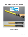
The Allflex RS320 Stick Reader
User Manual
EID_UM_07M1.1_EN
Allflex EID Readers with Dynamic Tuning NetworkTM
Congratulations for your acquisition of an Allflex EID reader.
This device is equipped with the new “DTN - Dynamic Tuning NetworkTM”
technology, an exclusive Allflex innovation (patent pending).
The “DTN - Dynamic Tuning NetworkTM” technology provides a significant
improvement of reader performance in several areas, including improved tag signal
reception, better noise immunity and increased read distance.
This is obtained by dynamically optimizing the electrical characteristics of the reader
antenna during tag activation and reception cycles.
2
Unpacking
The Allflex RS320 Stick Reader is offered for sale in several package types,
depending on the country of purchase. Please refer to local websites / brochures to
explain the specific package offered locally. As an example, Australia and New
Zealand offer “Standard” and “Premium Kit” packages.
The standard RS320 kit is shipped in a cardboard shipping box and includes:
• RS320 Reader
• Instruction Guide
• 1 x 9.6 Volt DC NiMH rechargeable battery pack
• 100 / 240VAC – 12VDC Trickle Charger
• Power / Data Cable
• Allflex Stick Reader Configurator© CD-ROM or NLIS Link software CDROM (Australia only)
• 5-metre power supply with alligator clips *
• Snap hook
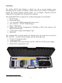
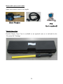
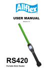
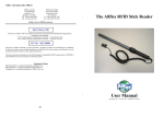
The “Premium Kit” is shown below and includes all of the items above except the
100 / 240VAC – 12VDC Trickle Charger, plus the following items.
• 2 extra 9.6 volt battery packs
• 1 extra serial cable
• AK320 Battery Pack Fast Charger and 100 / 240VAC-18VDC power supply
• Enclosed in a rugged plastic case
*
Not proposed for sale in Europe.
3
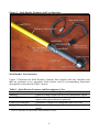
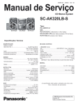
Figure 1 - Stick Reader Features and User Interface
Stick Reader User Interface
Figure 1 illustrates the Stick Reader’s features that comprise the user interface and
that are pertinent to its operation. Each feature and its corresponding functional
description is described in Table 1 below.
Table 1 - Stick Reader Features and Descriptions of Use
Feature
Description of Use
[1]
Antenna
Emits activation signal and receives transponder signal
Red LED Indicator
Illuminates whenever antenna is emitting activation
signal (when green button is pressed)
Green LED Indicator
Illuminates whenever a transponder has been read
[1]
Audible Beeper
Beeps once on first transponder reading and twice for
repeat
[1]
Item is internal to enclosure and cannot be seen.
4
Green READ Button
Data/Power Cable
DB9 Connector w/
DC Power Jack
Fiberglass Tube
Screw-on Endcap
Handle Grip
Cable Connector
Applies power and causes activation signal to be emitted
for reading transponder
Conveys external power to Reader and serial data to and
from Reader
Connects serial data to PC, scale head, or data logger
RS232 port. Accepts 12 VDC input as Reader power
source
Rugged, watertight enclosure
Provides access to battery compartment
Rubber anti-slip gripping surface
Electrical interface for attaching Data/Power Cable
5
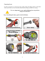
Preparing for use
In order to proceed, it is necessary first to fully charge the Battery Pack as described
below and to have an few electronic identification eartags available for testing.
It is very important to carry out the following three steps before
using the Stick Reader.
Step 1: Installing the battery pack in the Stick Reader
6
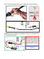
Step 2: Trickle charging the battery pack. (Applicable to the Standard Kit)
The Rapid Charger is available as an optional accessory, or as a standard item
in a “Premium Kit” package.
Rapid Charger – charged to
85% in 2hrs (Applicable to the
standard 720mAh batteries). If
larger batteries are offered in
the future, charge time will
extend in proportion. IE A
1000mAH would be around 3
hrs.
Spare Batteries can also be
purchased
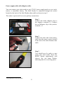
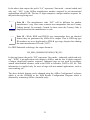
7
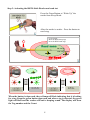
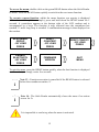
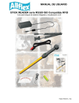
Step 3: Activating the RS320 Stick Reader and read test
Press the Green Button to “Wake Up” the
reader from Sleep Mode.
After the reader is awake – Press the button to
read a tag.
Typical read:
30cm for HDX sheep tags
39cm for HDX cattle tags
4
Read zone
30 / 39 cm
11,8 / 15,3 inches
No Read
> 3s
0001 HDX ISO:
982 00000115008
NO ID TAG
DETECTED!
When the button is depressed, the red lamp will flash indicating that it is looking
for a tag. Keep the green button depressed and when a tag is detected, the green
light will flash and the reader will emit a beeping sound. The display will show
the Tag number and the Count.
8
Stick Reader Power Supply
Power Source Requirements
The RS320 Stick Reader contains a 9.6VDC – 720mAh NiMH rechargeable battery
pack, which serves as its primary power source. Alternately, the RS320 can be
powered:
• From its external AC Adapter/Charger (Via the serial cable),
• Via the power supply cable with alligator clip * in conjunction with any
external DC power source (Input Rating 9-12 VDC – 1A).
• By connecting to older model battery packs (PW250) that were used with the
Grey (RS250) Allflex Stick Reader.
Special Notes Regarding Power Requirements
The older RS250 (Grey) stick readers can be powered by connecting directly to some
weigh scale heads (without the battery pack). The RS320 (Yellow) requires a higher
voltage level than most scales produce and hence cannot be used in the same manner,
unless the scale head is externally powered from a car battery, or AC charger.
Otherwise, the yellow reader must have its own charged battery inserted.
Note 1 - The RS320 Stick Reader is designed to operate only with the
Battery Pack provided. The RS320 will not operate with individual
battery cells of either disposable or rechargeable variety.
CAUTION
RISK OF EXPLOSION IF BATTERY IS REPLACED BY AN
INCORRECT TYPE.
DISPOSE OF USED BATTERIES ACCORDING
TO THE INSTRUCTIONS
*
Not proposed for sale in Europe
9
!
!
!
Note 2 - Do not use this apparatus near water when connected to AC/DC
adapter.
Note 3 - Do not install near any heat sources such as radiators, heat
registers, stoves, or other apparatus (including amplifiers) that produce
heat.
Note 4 - Unplug this apparatus during lightning storms or when unused
for long periods of time.
AC Adapter - The RS320 Stick Reader can be powered using its AC Adapter/Charger
regardless of the charge state of the Battery Pack. The AC Adapter can be used as a
power source even if the Battery Pack has been removed from the Stick Reader. If the
AC Adapter has been connected, the user may proceed with configuration and
performance testing while the Battery Pack is charging. This configuration could
affect reading performances.
Note 5 - The Stick Reader’s integral Battery Pack is affected by
temperature. At 0°C (32°F), the Battery Pack will deliver only about half
of its rated energy capacity. At lower temperatures, the Battery Pack
may deliver unsatisfactory performance. When the RS320 Stick Reader
is used in low temperature environments, connection to an external
power source, such as the Allflex PW250 Battery Pack, and placement of this
external Battery Pack close to the user’s body, is recommended.
!
Note 6 - To ensure proper Battery Pack charging, charging should be
conducted only in an environment where the temperature is between
15°C and 30°C (60°F to 85°F). Charging at temperatures outside these
boundaries will result in unsatisfactory charge acceptance by the Battery
Pack. For more information about the characteristics of rechargeable batteries, please
see the white paper at
[http://www.national.com/appinfo/power/files/f19.pdf#page=1].
!
10
Power supply cable with alligator cable *
You can connect your stick reader to any 12V DC power supply such as a car, truck,
tractor, or motorbike battery. The Stick Reader is connected through the socket
located on the back of the Stick Readers data cable as shown in step 2.
The reader is protected for reverse polarity connections.
Step 1
Connect the black alligator clip to
the negative terminal (-). Connect
the red alligator clip to the positive
terminal (+).
Step 2
Connect the other end of the battery
cable into the power socket located
at the end of the Stick Readers data
cable
Step 3
You should now be ready to start
using your stick reader. Press the
READ button momentarily and
observe the red lamp flashes,
indicating that it is receiving power.
*
Not proposed for sale in Europe
11
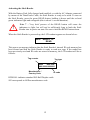
Activating the Stick Reader
With the Battery Pack fully charged and installed, or with the AC Adapter connected
by means of the Data/Power Cable, the Stick Reader is ready to be used. To turn on
the Stick Reader, press the green READ button, holding it down until the red and
green indicators light and extinguish (this is about ¼ second duration).
!
Note 7 - Very brief presses of the READ button will cause the
indicators to light, but will not be sufficiently long to latch the Stick
Reader into its power on state. Be sure to hold the READ button down.
When the Stick Reader is powered up, the LCD readout appears as shown below:
0000
READY TO
READ
This power-on message indicates that the Stick Reader's internal ID code memory has
been cleared and that the Stick Reader is ready to read new tags. If the reader has
been previously used and ID codes are stored in memory, the LCD readout will be as
follows:
Tag counter
Tag type
0002
HDX ISO:
982 000000000001
Manufacturer /
Country Code
ID code
HDX ISO: indicates standard ISO Half Duplex cattle.
982 corresponds to Allflex manufacturer code.
12
Display formats for other tag formats (other than ISO HDX tags) that can be read by
the RS320 Stick Reader are shown below for ISO FDX-B and industrial HDX coded
tags.
0002
FDX-B ISO:
982 009101723121
i
0014 TIRIS:2048
0000000000053925
Note 8 - Each ID Code is stored internally in the Stick Reader’s nonvolatile memory until the user deliberately erases the stored ID codes
after downloading them into a recording device, such as NLIS Link
(Australia only) or a PC database. Up to 3200 ID codes can be stored and
retrieved later at the user’s convenience.
Note 9 - The “Tag Counter” feature on the LCD readout can be reset to
zero at any time by double clicking the READ button, and observing the
LCD’s display “Reset Counter?”. Depressing the READ button again for
5 seconds, while this message is displayed on the screen will force the
Tag Counter to reset to the value “0000”. Resetting the Tag Counter does
not alter the ID codes previously read and stored in the Stick Reader’s internal
memory.
i
Note 10 - The Stick Reader provides a “New Animal Group” Function
that inserts a line of all zeroes into the list of RFID numbers stored. This is
used to separate mobs of stock in the memory. Each time you wish to
insert a “New Animal Group” you simply access the option via the menu
(2 quick button presses and trigger it by depressing the button for 5
seconds while the “New Animal Group” message is displayed. Inserting a “New
Animal Group” will not reset counter. Reset counter manually if required.
i
Note 11 - The Stick Reader will scan for duplicate tag numbers in a list
containing the last 100 tags scanned. This number (100) can be altered to
scan lesser values such as 25, 50, 75 or up to as many as all the tags in
memory. This is done using Allflex Stick Reader Configurator© Software
or by contacting Allflex Support. When a “New Animal Group” is
initiated, duplicate search is also reset.
i
13
i
Note 12 - Once activated, the reader will remain activated for 30 seconds.
This is the default value and can be configured from 1 second to 255
seconds, or to “Always On”. These changes are achieved using Allflex
Configurator© software.
Reading eartags
When a tag is successfully read, the tag's ID code information appears on the LCD
readout. For “non-duplicate” tag readings, the tag counter will be incremented and
the ID code is automatically stored in the Stick Reader's internal memory.
Tag numbers that are read as duplicates are not stored in memory and the counter is
not incremented. This means if you scan a tag twice within the Duplicate Search
Limit of 100 scans, it will be stored originally but not the second time. If you scan the
same tag twice outside the Duplicate Search Limit of 100 tags, the number will be
stored twice and the counter will be incremented for both scans.
The Stick Reader's green LED indicator flashes and the buzzer will sound for every
scan. A single flash/beep occurs the first time a tag is read and a double flash/beep
indication occurs for duplicate tag reading.
Every time a tag is scanned, according the Stick Reader configuration (send repeats,
do not send repeats or send upon re-read), the number can be transmitted or not out of
the serial data cable / Bluetooth® ports if it is a duplicate.
Using the function menu
A menu is available on the Stick Reader that groups together 4 functions. These four
functions are used:
• To reset the tag counter to zero.
• To create a New Animal Grouping (“New Animal Group” Field - a line of
zeros – 000000000000).
• To reset the Stick Reader configuration (Factory Settings).
• To enable Bluetooth®.
14
To access the menu, double-click on the green READ button when the Stick Reader
is awake. Press the READ button quickly to switch to the next menu function.
To execute a menu function, whilst the menu function you require is displayed
(“New Animal Group” for example), press and hold down the READ button for 5
seconds. A countdown appears at the bottom right of the LCD readout and is
accompanied by a beep. The function is only executed once the countdown has
reached ‘0’ and a long beep is sounded. A confirmation message is then displayed on
the readout.
NEW ANIMAL
GROUP
- BY LONG
PRESS
RESET
COUNTER?
- BY LONG
PRESS
RESET CONFIG?
- BY LONG
PRESS
ENABLE
BLUETOOTH
- BY LONG
PRESS
FIRMWARE
VERSION
QUIT
MENU
To quit the menu, press the READ button quickly when the last function is displayed
on the readout, or simply wait a few seconds.
i
i
Note 13 - Function execution is cancelled if the READ button is released
before the countdown reaches ‘0’.
Note 14 - The Stick Reader automatically closes the menu if no action
occurs for 3s.
It is impossible to read a tag when the menu is activated.
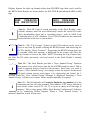
15
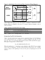
Read Range Performance
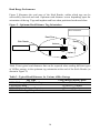
Figure 2 illustrates the read zone of the Stick Reader, within which tags can be
successfully detected and read. Optimum read distance occurs depending upon the
orientation of the tag. Tags and implant read best when positioned as shown below.
Figure 2 - Optimum Read Distance Tag Orientation
Best Orientation
Read Zone
Stick Reader
Eartag
Antenna
Implant
Table 2 lists typical read distances that can be expected when reading different types
of Allflex eartags, in the optimum tag orientation at the end of the Stick Reader (as
shown in Figure 2).
Table 2 - Typical Read Distances for Various Allflex Eartags
Tag Type
Using charged battery pack
HDX/HP Eartag (NLIS/Cattle Tag)
39 cm or 15.5 inches
FDX-B/HP Eartag
34 cm or 13.5 inches
HDX/LW Eartag (Sheep / Swine)
30 cm or 12 inches
FDX-B/LW Eartag (Sheep / Swine)
32 cm or 12.5 inches
16
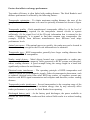
Factors that affect read range performance
Tag reader efficiency is often linked with reading distance. The Stick Reader's read
distance performance is affected by the following factors:
Transponder orientation - To obtain maximum reading distance, the axes of the
transponder and reader antenna coils must be optimally orientated as shown in Figure
2.
Transponder quality - Each manufacturer's transponder differs by (a) the level of
exciter signal energy required for the transponder internal circuits to operate
sufficiently, (b) the signal level of the ID code information that is returned to the
reader. Consequently, it is normal to find that common type transponders (for
example, FDX-B) from different manufacturers have different read range
performance levels.
Animal movement - If the animal moves too quickly, the reader may not be located in
the read zone long enough for the ID code information to be obtained.
Transponder type - HDX transponders generally have larger reading distances than
similar-sized FDX-B transponders.
Nearby metal objects - Metal objects located near a transponder or reader may
attenuate and distort the magnetic fields generated in RFID systems and therefore,
reduce reading distance. A good example being the eartag caught in a head bale
significantly reduces the read distance.
Electrical noise interference - The operating principle of RFID transponders and
readers is based on electromagnetic signals. Other electromagnetic phenomena, such
as radiated electrical noise from other RFID tag readers, or computer screens may
interfere with RFID signal transmission and reception and therefore, reduce reading
distance.
Transponder/reader interference - Several transponders in the reception range of the
reader, or other readers that emit excitation energy close by may adversely affect
reader performance or prevent the Stick Reader from operating.
Discharged battery pack - As the battery pack discharges, the power available to
activate the field becomes weaker and this reduced field results in a reduced reading
range.
17
ID Code Memory
The Stick Reader has an internal non-volatile memory that can store 3200 ID codes.
Non-volatile memory means that the data in memory will not be lost even if the
battery goes flat. Non-volatile memory is only cleared by sending a specific
command to the reader. This is done from software like NLIS Link (Australia only)
or HyperTerminal® etc.
ID codes are stored automatically when they are read. A transponder ID code will not
be stored several times if the same tag is read successively several times, but if the
reader is configured by the user to have the “Duplicate Search” function set to “Last
Tag”, It will be stored several times in memory if other tags are read in between.
When more than 3200 ID codes are read, the new ID codes overwrite the oldest ID
codes in memory.
18
Using the Stick Reader’s Serial Data Interface
The RS232 serial data interface is available on the RS320 by connecting the
detachable Data/Power Cable to the Cable Connector located on the Endcap. The
Stick Reader’s Cable Connector is covered with a protective cap to guard against
foreign material contamination. Remove this cap and install the Data/Power Cable by
engaging the connector and rotating the lock-ring.
The RS232 serial interface comprises a 3-wire arrangement with a DB9F connector,
and consists of transmit (TxD/pin 2), receive (RxD/pin 3), and ground (GND/pin 5).
Figure 3 illustrates the power and data wiring of the Power Jack and Data Connector.
This interface is factory configured with the default settings of 9600 bits/second, no
parity, 8 bits/word, and 1 stop bit (“9600N81”). These parameters can be changed by
using the options included in the Configurator© program.
i
Note 15 - The RS320 Stick Reader is provided with the connectorized
endcap and detachable Data/Power cable in its standard configuration.
Note 16 - The Stick Reader RS232 interface is wired as a DCE (data
communications equipment) type that connects directly to the serial port of
a PC or any other device that is designated as a DTE (data terminal
equipment) type. When the Stick Reader is connected to other equipment that is
wired as DCE also (such as a Palm Pilot or Pocket PC), a “null modem” adapter is
required in order to properly cross-wire transmit and receive signals so that
communications can occur.
i
i
Note 17 - The Stick Reader’s serial data connection can be extended using
a standard DB9M to DB9F extension cable. Extensions longer than 20
meters (~65 feet) are not recommended for data, and extensions longer that
2 meters (~6 feet) are not recommended for data and power.
19
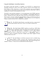
Figure 3 - Stick Reader Power Jack and Data Connector Wiring Diagram
Serial output data appears on the Stick Reader’s TxD/pin 2 connection in ASCII
format, which is compatible with most PC terminal emulator programs, such as
HyperTerminal®.
Table 3- Default Serial Data ID Code Formats
Tag Type
Default Format
HDX ISO
LA_982_000001088420{CR}{LF}
HDX Industrial
LR_0006_0000000018514243{CR}{LF}
FDX-B ISO
LA_982_000000255895{CR}{LF}
Note: _ = space; {CR} = carriage return; {LF} = line feed
Interpreting Tag ID Code Information
Table 3 lists the default data formats that are transmitted from the Stick Reader’s
serial communications port, in response to reading compatible type tags. For ISO
type tags, there is no contextual differentiation between HDX and FDX-B outputs.
Both types of tags produce a default format:
LA_982_000001088420{CR}{LF}
Where the underscore “_” represents a space character, and {CR}{LF} is a carriage
return /line feed (unprinted / invisible control characters which cause a PC’s display
cursor to jump to the beginning of the next line prior to displaying the next ID
number).
20
In the above data output, the prefix “LA” represents “line mode – animal coded read
only tag”, “982” is the Allflex manufacturer number assigned by an international
organization called ICAR. The last 12 digits comprise a unique number sequence for
the particular tag being read.
i
Note 18 - The manufacturer code “982” will be different for another
manufacturer’s tag. Also some countries use transponders that use Country
Coding instead, for example, Canada. In these cases the Country Code is
displayed and not the manufacturer’s code.
i
Note 19 - While HDX and FDX-B type transponders have an identical
format, they are guaranteed by Allflex to be unique. That is, HDX tag type
ID numbers are never duplicated in FDX-B type tags, despite their sharing
the same manufacturer ID code (“982”).
For HDX Industrial coded tags, the output format is:
LR_0006_0000000018514348{CR}{LF}
In this tag format, the prefix “LR” represents “line mode – industrial coded read only
tag”, “0006” is an application code unique to Allflex, and the last 16 digits comprise
a unique identifying number sequence. Industrial tags are not used in regulatory
animal identification schemes, such as the NLIS in Australia, NAIT in NZ, etc. This
information is supplied only for users of tags with non animal applications, such as
asset tracking, etc…
The above default formats can be changed using the Allflex Configurator© software
which is on the CDROM or the Stick Reader Configuration Program which is
obtained by contacting Allflex (Australia only).
21
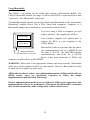
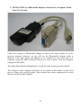
Using Bluetooth®
The CM301 is an endcap for the reader that contains a Bluetooth® module. The
CM301 Bluetooth® module (see page 36) allows the RS320 to send and receive data
“wirelessly” via a Bluetooth® connection.
To make Bluetooth® operate you need to connect the Bluetooth® reader with another
Bluetooth® enabled device, like a PDA (hand held computer), computer, or a
Bluetooth® dongle that is attached to a scale head (as shown below).
If you are using a PDA or computer you will
require software. (Not supplied by Allflex)
Stock Weigh
Electronic
Scale Head
Your software supplier will explain how to
connect the PDA, or your computer to the
Allflex Reader.
Bluetooth® works on a premise that one end of
the communications will be a MASTER and
Bluetooth Module
the other a SLAVE. The MASTER initiates
connected to serial port
communications and looks for a SLAVE
device it has been connected to. PDAs and
computers usually behave as MASTERS.
WARNING: When used in the appropriate manner and setup correctly, Bluetooth®
offers an excellent method of cable free data transfer. However, Bluetooth® can also
be made far too complex by some users.
Allflex advises that to achieve successful implementation of Bluetooth® with our
RS320 reader, users are specifically requested to follow the simple
implementation methods listed (following).
If these implementation methods are not followed, Allflex cannot guarantee that
implementation will not be problematic. This means the Bluetooth® connection
may become inconsistent, thus causing other reader related errors.
22
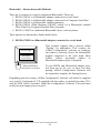
Bluetooth® – Known Successful Methods
There are 5 scenarios to correctly implement Bluetooth®. These are:
1. RS320+CM301 to a Bluetooth® adapter connected to a scale head.
2. RS320+CM301 to a Bluetooth® adapter connected to a Computer Serial Port.
3. RS320+CM301 to a Bluetooth® enabled computer.
4. RS320+CM301 (With Hardware ON/OFF switch * ) to a Bluetooth® enabled
PDA (Palm Top Computer/Portable Data Assistant)
5. RS320+ CM301 to a dedicated Bluetooth® device, such as printer.
These options are discussed in further detail below.
1. RS320+CM301 to a Bluetooth® adapter connected to a scale head.
Stock Weigh
Electronic
Scale Head
Bluetooth Module
connected to serial port
This scenario requires that a process called
“Pairing” be undertaken. This requires the
Allflex Configurator© software to configure
the reader to correctly link to the Bluetooth®
module connected to the scale head. Most
Allflex offices pre-match readers to
Bluetooth® adapters prior to dispatch.
If your RS320 and Bluetooth® adapter have
not been set up for you, or have lost their
pairing, Allflex Configurator© Software will
be required to complete the Pairing Process.
Depending upon the country, Allflex Configurator© Software will either be supplied
on a specific Configurator© CD supplied with the reader, or included on other CD’s
such as NLIS Link in Australia. Install the Configurator© Software. The scale head
serial port must supply power on pin 9.
*
Please contact your Allflex reseller for this specific Bluetooth module
23
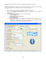
Connect the wand to the PC via the serial cable and computer serial port.
Start the Configurator© software and turn on the reader. The reader’s current settings
will appear on the screen. If they don’t, click on “Get Settings”.
• The Configurator© has several TABS across the top section.
• Select the “Wireless Technologies” screen by clicking on the “Wireless
Technologies” Tab.
• The Stick Reader settings must be set to the following:
o Power Module: ON
o Connection Mode: MASTER
o Device Pairing: ON
o Pairing Slave ID; use the address code found on the small label on the
Bluetooth® Adapter that attaches to the scale head. The code will
usually look something like this: 000BCE0076A3
24
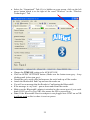
• Select the “Operational” Tab (if it is hidden on your screen, click on the left
arrow button which is to the right of the word “Wireless” on the “Wireless
Technologies” Tab.
• Change the TIME ON setting to be ALWAYS ON.
• Click on APPLY SETTINGS button. (Make sure the button turns grey – keep
clicking until it does turn grey)
• Detach the curly serial cable and unscrew the serial end cap off the reader.
• Attach the Bluetooth® End Cap and turn the reader on.
• You will see a message that the Reader is Configuring the Bluetooth®.
• If the message is very brief – power down and restart the reader.
• Make sure the Bluetooth® adapter is attached to the correct port of your scale
head (CON2 on a Tru-Test XR) Also ensure the XR is powered up.
• Note: If the Bluetooth® Receiver adapter is not plugged into CON2 on an XR
it will not work as this is where it receives power.
25
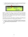
• A Bluetooth® symbol will appear next to the counter on the top left hand-side
of the stick reader display indicating it is connected. Data should now transfer
from the wand to the scale head when you scan a tag.
Note 20 - the Bluetooth® settings are saved in the WAND not the Bluetooth®
endcap. For example, if you configure a wand to talk to a specific Bluetooth®
receiver adapter, you can swap the Bluetooth® endcap on the reader and the system
will continue to work as expected. If you swap the wand however, the connection
will not work, unless you program the new wand to connect to the Bluetooth®
adapter attached to the scale head.
The settings are stored in the reader memory. The settings are NOT applied to the
CM301 Bluetooth® module until the module is fitted to the reader and it is powered
up. At this point the screen will say “Configuring Bluetooth® Module”
i
Note 21 - Because you have set the TIME ON setting to ALWAYS ON,
the only way to power the reader down is to unscrew the endcap and
allow the battery to momentarily detach.
26
2. RS320+CM301 to a Bluetooth® adapter connected to a Computer Serial
Port (Not for sale).
Under this scenario, a Bluetooth® adapter is used in the same manner as in the
previous scenario, however, as you will see the Bluetooth® Adapter cable is
different. This cable allows the adapter to be connected to the serial port of a
computer (using the DB9 connector) and also to receive power from the computer
(using the USB cable).
The reader Bluetooth® configuration is exactly the same as the previous scenario.
The software on the computer should be set to connect to the reader, via the serial
port as if there was a cable in place. This scenario also allows computers to be used
that are not Bluetooth® enabled.
27
3. RS320+CM301 to a Bluetooth® enabled computer.
The reader should be a SLAVE, PAIRING OFF, TIME ON = ALWAYS ON
(Configured using the Allflex Stick Reader Configurator© program).
Tips
Sometimes, a PIN code is required to connect the “Stick Reader RS320 – RF
Bluetooth®” to the PC, PDA… In such case, the PIN code to use is (case sensitive):
default
28
4. RS320+CM301 (With Hardware ON / OFF switch) to a Bluetooth®
enabled PDA (Palm Top Computer / Portable Data Assistant)
To Be Advised.
29
5. RS320+CM301 to a dedicated Bluetooth® device such as printer.
Under this scenario, the Allflex Configurator© software is used to set the Power
Module: ON
Connection Mode: MASTER
Device Pairing: ON
Pairing Slave ID: Use the ID HEX Code for the Bluetooth® module of the printer.
Sometimes this is not written on the device. One way to find the address for the
Bluetooth® printer is to use a computer or PDA with Bluetooth® and discover the
printer and then view the Details. Once you know the address, enter it into the
“Pairing Slave ID” field. All the settings above are in the “Wireless Technologies”
Tab.
It is recommended that the TIME ON setting in the “Operational” Tab also be set to
ALWAYS ON.
It may also be necessary to adjust the data string being sent to some printers to get the
correct data onto the label. In the case of the Zebra QL320 printer shown, we set the
COMMAND PROMPT (in the “ID-Code Format” Tab) to: NO PROMPT (default
value).
30
NOTES:
31
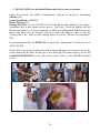
Optional accessories for the RS320 Stick Reader
CM301 Bluetooth® Module
The Bluetooth® module provides wireless communication between the RS320 and a
Bluetooth®-compatible device. The maximum range of this wireless link could reach
100 m depending on the environment, if allowed by the matching Bluetooth®
compatible device.
This device contains FCC-ID POOWML-C30XX and is approved in accordance to
R&TTE directive transmitter module marked by CE product label, manufactured by
MITSUMI incorporated to OEM module.
100m
PC +Bluetooth option
(not supplied)
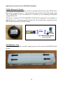
PW320 Battery Pack
The PW320 Battery Pack is used to supply power to all versions of the RS320 Stick
Reader.
32
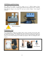
AK320 Battery pack fast charger
The AK320 fast charger is used to charge up to 3 PW320 Battery Packs
simultaneously in 2 hours. A flashing light indicates rapid charging mode. A flashing
light indicates charge is less than 85% and not in trickle charge / fully charged
condition.
Battery orientation!
PW250 Battery Pack
The PW250 Battery Packs are portable power sources typically used for the older
version RS250 (Grey) Allflex Stick Reader. These batteries can also be used to power
the RS320 Stick Reader. The PW250 provides power for approximately 4000 read
cycles. It can be fully recharged in 10h and only requires 2.5h to be recharged to 80%
capacity.
*
RS320 Stick
Reader
33
PC
(Not supplied)
Removable curly serial cables
Spare serial cables exist in 3m lengths.
Plastic Carry Case
Durable Plastic Carry Case is available as an optional extra or is included in the
“Premium Kit” Package.
34
Serial Command Language
This section is designed for the use of programmers and advanced users.
The instructions listed in Table 4, describe some of the basic and more frequently
used configuration options. It illustrates how to implement them using the Stick
Reader Serial Command Language in conjunction with HyperTerminal®. The
Command Language method uses upper and lower case alpha characters combined
with hexadecimal characters to establish the Reader’s configuration.
Table 4 - Frequently used command language characters
Command
Application
P
The reader's current settings are sent in command language
format
Bnnnnnn
Configures the ID code serial data format
Snn
Sets serial data communication parameters
Inn
Sets the miscellaneous options
r
Resends the last tag read
R
Initiates reading (the Stick Reader must already be powered
up)
G
Retrieves all the ID codes stored in memory
Mnn
Sets ID code memory options
C{Enter}
Clears the ID code memory
? or H
Retrieves the list of valid command language characters
i
Note 22 - For commands followed by “n” (hexadecimal characters), the
user must press the {Enter} key on the PC after entering all the command
characters. {Enter} does not need to be pressed for single letter commands,
except as indicated in Table 1. For more details about the parameter “n”, the
user should contact Allflex.
35
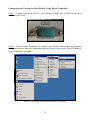
Connecting and Testing the Stick Reader Using HyperTerminal®
Step 1 - Connect the serial cable to the computers COM port (COM1 is the most
common port used).
Step 1 – Connecting to COM port 1
Step 2 - Launch HyperTerminal® by going to the START button, then to Programs
then to accessories then to Communications and finally click on the HyperTerminal®
icon to launch the program.
Step 2 - Selecting The HyperTerminal® Program
36
HyperTerminal® comes standard with most windows installation. It can also be
downloaded free from
http://www.hilgraeve.com/htpe/index.html
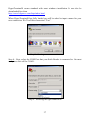
When HyperTerminal® has fully loaded you will be asked to input a name for your
new connection. We’ll call this connection “Test”.
Step 3 - Starting a new connection
Step 4 - Next, select the COM Port that your Stick Reader is connected to. On most
computers this will be COM 1.
Step 4 – Selecting the right connection
37
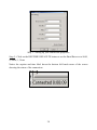
Step 5 - Setting up your connection properties
Step 5 - Click on the RESTORE DEFAULTS button to set the Baud Rate etc to 9600,
8, None, 1, None
Notice the caption and time label down the bottom left hand corner of the screen
showing the status of the connection.
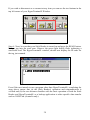
38
If you wish to disconnect or re-connect at any time you can use the two buttons in the
top left corner of your HyperTerminal® Window.
Step 6 - Next, be sure that your Stick Reader is turned on and press the READ button.
Bring a tag into the read zone. Observe the green light briefly flash, indicating a
successful read. The HyperTerminal® window, should now display the ID code for
the tag just scanned.
Even if the user intends to use a program other than HyperTerminal®, completing the
steps above ensure that (a) the Stick Reader’s operation and communication is
verified and (b) the user becomes familiar with the basic operation of both the Stick
Reader and HyperTerminal® as a backup application to other specific data transfer
such as NLIS Link (Australia only).
39
Stick Reader physical integrity
The Stick Reader has been built from rugged and durable materials to withstand use
in harsh environments for long periods of time. However, the Stick Reader contains
electronic components that can be damaged if they are deliberately exposed to
extreme abuse. This damage can adversely affect, or stop the Reader's operation. The
user must avoid deliberately striking other surfaces and objects with the Stick Reader.
Damage that results from such handling is not covered by the warranty described
below.
Limited Product Warranty
Allflex guarantees this product against all defects due to faulty materials or
workmanship for a period of one year following the date of purchase. The warranty
does not apply to any damage resulting from an accident, misuse, modification or an
application other than that described in this manual and for which the device was
designed.
If the product develops a malfunction during the warranty period, Allflex will repair
or replace it free of charge. The cost of shipment is at the customer's expense,
whereas return shipment is paid by Allflex.
Refer all servicing to qualified service personnel. Servicing is required when the
apparatus has been damaged in any way, such as power-supply cord or plug is
damaged, liquid has been spilled or objects have fallen into the apparatus, the
apparatus has been exposed to rain or moisture, does not operate normally, or has
been dropped.
40
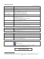
SPECIFICATIONS
EID_TS070002 Rev 1.1
Operating frequency
134.2 kHz
Standards
ISO 11784, ISO 11785
Tag compatibility
HDX, FDX-B
Reading distance[*]
Allflex HDX HP Ø 30mm: 39cm
Allflex FDX-B HP Ø 31mm: 34cm
Allflex HDX LW Ø 26.4mm: 30cm
Allflex FDX-B LW Ø 26.4mm: 32cm
Using charged battery
pack
(w/o AC adapter)
Memory
User interface
Comm. Interfaces
3200 ID tags in a non volatile memory
2 x 16 characters backlit readout
Red LED “Exciter active”
Audible beeper and green LED “Good Read”
One “Press to Read” push button
RS232 Serial Data Port (9600/N/8/1) – 1m coiled cable
Bluetooth® (optional)
Comm. data format
Decimal or hexadecimal in ASCII format
Features
Retagging counter and user code management
Software upgradeable via RS232 Serial Port
Battery pack
Internal removable rechargeable 9.6V NiMH battery pack
Power supply
Input: 100-240VAC – 50/60Hz
Output: 12VDC – 1.5A
Temperature range
-10°C to +55°C
Material
Yellow fiberglass tube enclosure and black ABS plastic
Dimensions
L x D: 600 x 32mm or 450 x 32mm
Weight
60cm model: 660g (23 ounces)
45cm model: 570g (20 ounces)
Certifications
Ref: SE-49151
Part 15.209, Subpart C (FCC ID: NQY – 930041)
These specifications may vary depending on the technical improvements
ISO 11784 & 11785
*
Measured in a clean environment (no metallic object at less than 2 meters, devices generating radiated emissions are
kept away from the reader). EID tags are placed in best orientation and have a resonance frequency at 134.2 kHz.
41
This device complies with the standards set forward by the International
Standardization Organization. Specifically with standards
11784: Radio frequency identification of animals -- Code Structure
11785: Radio frequency identification of animals -- Technical Concept.
FCC ID: NQY-930041
This device complies with Part 15 of the FCC Rules. Operation is subject to the
following two conditions: (1) this device may not cause harmful interference, and
(2) this device must accept any interference received, including interference that
may cause undesired operation.
Trademark Notices
HyperTerminal® is a registered trademark of Hilgraeve, Inc.
MS-Windows® is a registered trademark of Microsoft, Inc.
Configurator© is a registered trademark of Allflex USA, Inc.
Bluetooth® is a registered trademark of Bluetooth SIG, Inc.
42
43
Allflex Offices
Allflex Europe (UK) Ltd.
Unit 6 - 8 Galalaw Business Park
HAWICK
United Kingdom
TD9 8PZ
Phone: 44 (0) 1450 364120
Fax: 44 (0) 1450 364121
www.allflex.co.uk
Allflex USA, Inc.
P.O. Box 612266
2805 East 14th Street
Dallas Ft. Worth Airport, Texas 752612266
United States of America
(800) 989-TAGS [8247]
(972) 456-3686
(972) 456-3882/FAX
www.allflexusa.com
Allflex International Do Brasil Ltda.
Rua Monte serrat, 1097
CEP 03312-001
Tatuape, SP, Brazil
Phone/Fax: (55) 11 6942-7008
www.allflex.com.br
Allflex Beijing Plastics
No. 3 Heng Qu Tiao Dong
Tie Jiang Ying Feng Tai District
Beijing, China 100078
Phone: 861 762 9541
Fax: 861 762 9514
Allflex Europe S. A.
ZI DE Plague
Route des Eaux
35502 Vitre, France
Téléphone/Phone: 33 (0)2 99 75 77 00.
Télécopieur/Fax: 33 (0)2 99 75 77 64
www.allflex-europe.com
Allflex S.A. Boulder
2820 Wilderness Place, Suite A
Boulder, Colorado 80301
United States of America
Phone: (303) 449-4509
Fax: (303) 449-4529
www.allflex-boulder.com
Allflex Argentina S.A.
Las Heras 1588
1641 Martinez
Buenos Aires, Argentina
Phone/Fax: 54 11 4792 3488
Allflex Australia
33-35 Neumann Road
Capalaba
Queensland 4157 Australia
Phone: 61 7 3245 9100
Fax: 61 7 3245 9110
www.allflex.com.au
Allflex Canada
Corporation Allflex Inc.
4135, Bérard
St-Hyacinthe, Québec J2S 8Z8 Canada
Téléphone/Phone: (450) 261-8008
Télécopieur/Fax: (450) 261-8028
Allflex New Zealand
Private Bag 11003
17 El Prado Drive
Palmerston North
Phone: 64 6 3567199
Fax: 64 6 3553421
www.allflex.co.nz
44