1
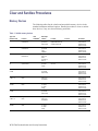
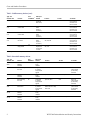
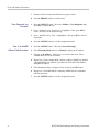
xx
ZZZ
WVR7200 Waveform Rasterizer
Declassification and Security
Instructions
www.tektronix.com
*P077067200*
077-0672-00
Copyright © Tektronix. All rights reserved. Licensed software products are owned by Tektronix or its subsidiaries
or suppliers, and are protected by national copyright laws and international treaty provisions.
Tektronix products are covered by U.S. and foreign patents, issued and pending. Information in this publication
supersedes that in all previously published material. Specifications and price change privileges reserved.
TEKTRONIX and TEK are registered trademarks of Tektronix, Inc.
Contacting Tektronix
Tektronix, Inc.
14150 SW Karl Braun Drive
P.O. Box 500
Beaverton, OR 97077
USA
For product information, sales, service, and technical support:
In North America, call 1-800-833-9200.
Worldwide, visit www.tektronix.com to find contacts in your area.
Table of Contents
Preface .............................................................................................................. iii
Clear and Sanitize Procedures..................................................................................... 1
Memory Devices............................................................................................... 1
Data Export Devices........................................................................................... 5
Troubleshooting..................................................................................................... 5
How to Clear or Sanitize a Non-Functional Instrument ................................................... 5
How to Recover from Clearing or Removing the Instrument’s Memory ................................ 5
WVR7200 Declassification and Security Instructions
i
Table of Contents
ii
WVR7200 Declassification and Security Instructions
Preface
This document helps customers with data security concerns to sanitize or remove
memory devices from the WVR7200 Waveform Rasterizer.
These products have data storage (memory) devices. These instructions tell
how to clear or sanitize the memory devices. The instructions also tell how to
declassify an instrument that is not functioning.
Products
Related Documents
This document covers all WVR7200 instruments.
The following table lists the documentation that is available for the product and
shows where you can find it: in a printed manual, on the product documentation
CD-ROM, or on the Tektronix Web site.
Table i: Product documentation
Item
Purpose
Location
User Manual
(077-0668-XX)
Provides operation and application
information. This manual is available
in English, Japanese, and Simplified
Chinese.
Product Documentation CD and available at
www.tektronix.com/downloads
Online Help
In-depth instrument operation and UI
help.
On the instrument
Specifications and Performance
Verification Technical Reference
(077-0670-XX)
Specifications and procedures for
checking instrument performance.
Product Documentation CD and available at
www.tektronix.com/downloads
WFM and WVR Series
Management Information
Database (MIB) Programmer
Manual
(077-0261-XX)
SNMP command reference for remotely
controlling the instrument.
Product Documentation CD and available at
www.tektronix.com/downloads
Service Manual
(077-0676-XX)
Provides information about adjustments,
repair, and replaceable parts.
Available at www.tektronix.com/downloads
Installation and Safety Instructions
(071-3024-XX)
Provides safety and compliance
information along with hardware
installation instructions to present
the associated safety warnings.
This manual is available in English,
Japanese, and Simplified Chinese.
Printed manual and also available in electronic
format at www.tektronix.com/downloads
WVR7200 Declassification and Security Instructions
iii
Preface
Terms
The following terms may be used in this document:
Clear. This removes data on media/memory before reusing it in a secured
area. All reusable memory is cleared to deny access to previously stored
information by standard means of access.
Erase. This is equivalent to clear.
Media storage/data export device. Any of several devices that can be used
to store or export data from the instrument, such as a USB port.
Nonvolatile memory. Data is retained when the instrument is powered off.
Power off. Some instruments have a “Standby” mode, in which power is
still supplied to the instrument. For the purpose of clearing data, putting the
instrument in Standby mode does not qualify as powering off. For these
products, you will need to either press a rear-panel OFF switch or remove the
power source from the instrument.
Remove. This is a physical means to clear the data by removing the memory
device from the instrument. Instructions are available in the product Service
Manual.
Sanitize. This eradicates the data from media/memory so that the data cannot
be recovered by other means or technology. This is typically used when the
device will be moved (temporarily or permanently) from a secured area to a
non-secured area.
Scrub. This is equivalent to sanitize.
User-modifiable. The user can write to the memory device during normal
instrument operation, using the instrument interface or remote control.
Volatile memory. Data is lost when the instrument is powered off.
iv
WVR7200 Declassification and Security Instructions
Clear and Sanitize Procedures
Memory Devices
The following tables list the volatile and nonvolatile memory devices in the
standard instrument and listed options. Detailed procedures to clear or sanitize
these devices, if any, are shown following each table.
Table 1: Volatile memory devices
Type and
minimum size
Function
User
modifiable 1
Data input
method
Location
To clear
To sanitize
FPGA 1.3 K
Audio
measurement
No
Programmed
by onboard
flash memory
Plugs into optional
Digital Audio board, IC8
on Dolby Audio board
None
Remove the power
source from the
instrument for at
least 20 seconds
FPGA 920 KB
Audio
measurement
No
Programmed
by onboard
serial
EEPROM
U610 on Audio board
None
Remove the power
source from the
instrument for at
least 20 seconds
DSP RAM 32kx8
Audio
Measurement
No
Programmed
from main
board
processor at
boot up
Audio board U410
None
Remove the power
source from the
instrument for at
least 20 seconds
DDR2 RAM 32M x
16
Microprocessor
system memory
No
Written by
processor
system
Main board, U6, U36,
U53, U73
None
Remove the power
source from the
instrument for at
least 20 seconds
FPGA, DSP1
4.3 MB
Mapper #1
No
Programmed
by onboard
flash memory
Main board, U97
None
Remove the power
source from the
instrument for at
least 20 seconds
QDR2 RAM
1 MB X 18
Mapper #1 RAM
DSP1
No
Dynamic
memory for
FPGA DSP1
Main board, U4, U43
None
Remove the power
source from the
instrument for at
least 20 seconds
DDR2 32M X
16 RAM
Mapper#1 RAM
DSP1
No
None, Part
is unused
in current
design
Main board, U21
None
Remove the power
source from the
instrument for at
least 20 seconds
FPGA DSP2
4.3 MB
Mapper #2
No
Programmed
by onboard
flash memory
Main board, U161
None
Remove the power
source from the
instrument for at
least 20 seconds
QDR2 RAM
1 MB X 18
Mapper #2 RAM
DSP2
No
Dynamic
memory for
FPGA DSP2
Main board, U20, U162
None
Remove the power
source from the
instrument for at
least 20 seconds
DDR2 32M X
16 RAM
Mapper#2 RAM
DSP2
No
None, Part
is unused
in current
design
Main board, U163
None
Remove the power
source from the
instrument for at
least 20 seconds
WVR7200 Declassification and Security Instructions
1
Clear and Sanitize Procedures
Table 1: Volatile memory devices (cont.)
Type and
minimum size
Function
User
modifiable 1
Data input
method
Location
To clear
To sanitize
FPGA, DSY2 5 MB
Rasterizer FPGA
No
Programmed
by onboard
flash memory
Main board, U93
None
Remove the power
source from the
instrument for at
least 20 seconds
DDR2 DSY 32 MB
X 32
Frame Buffer #1
for DSY FPGA
Yes
User can
initiate
capture to
this memory
Main board, U23, U65
None
Remove the power
source from the
instrument for at
least 20 seconds
DDR2 DSY 32 MB
X 32
Frame Buffer #2
for DSY FPGA
Yes
User can
initiate
capture to
this memory
Main board, U44, U45
None
Remove the power
source from the
instrument for at
least 20 seconds
DDR2 DSY 32 MB
X 80
Capture Buffer for
DSY FPGA
Yes
User can
initiate
capture to
this memory
Main board, U91, U92,
U94, U95, U96
None
Remove the power
source from the
instrument for at
least 20 seconds
DSY SRAM
DSY FPGA
Display SRAM
yes
Stores
Graphics and
text as shown
on screen
Main board, U46, U47,
U48, U49
None
Remove the power
source from the
instrument for at
least 20 seconds
1
During normal instrument operation.
Table 2: Nonvolatile memory devices
Type and
minimum size
User
modifiable 1
Data input
method
Location
To clear
To sanitize
Serial EPROM
256x8
Stores SDI
calibration
coefficients
No
Programmed
during
calibration
SDI board, U343
Recalibrate SDI
None
PLD
General decoding
and control
No
Programmed
by software
during software
upgrade
SDI board, U641
None
Reload the
system software
per the loading
instructions
Serial EPROM
Stores Eye
calibration
coefficients
No
Programmed
during
calibration
Eye board, U343
Recalibrate Eye
None
PLD
General decoding
and control
No
Programmed
by software
during software
upgrade
Eye board, U641
None
Reload the
system software
per the loading
instructions
Flash Memory
4 MB
Audio
measurement
No
Programmed
by software
during software
upgrade
Plugs into optional Digital
Audio board, IC9 on Dolby
Audio board
None
Reload the
system software
per the loading
instructions
Serial EEPROM
256 X 8
Stores audio
calibration
coefficients
No
Programmed
during
calibration
U0360 on Audio board
Recalibrate Audio
None
Serial EEPROM
256 X 8
Stores Composite
calibration
coefficients
No
Programmed
during
calibration
U12 on Composite board
Recalibrate Composite
None
2
Function
WVR7200 Declassification and Security Instructions
Clear and Sanitize Procedures
Table 2: Nonvolatile memory devices (cont.)
Type and
minimum size
User
modifiable 1
Data input
method
Location
To clear
To sanitize
NAND Flash
256 M X 8
Not used but
is checked in
power-up self-test
No
None
Main board, U103
None
None
NOR Flash 128 M
X 16
Loads FPGAs on
power up, contains
instrument SW,
network access
parameters, and
user-defined
presets
yes
Programmed
by software
during software
upgrade
Main board, U101, U102
Clear Presets and
re-load instrument SW.
this does not clear the
factory-assigned MAC
address.
None
NVSRAM plus
Real Time Clock
Stores time set by
user and Network
parameters,
Option Key,
Instrument Type,
Diagnostic log and
last instrument
state.
Yes
User Interface
Main board, U11
Set time to GMT.
Clear diagnostic log,
Clear network settings,
restore factory preset
then power down.
None
PLD, Glue
Programs DSP
and DSY FPGAs
and and general
control and
decoding.
No
Programmed
by software
during software
upgrade
Main board, U19
None
Reload the
system software
per the loading
instructions
Serial Flash DSP1
32 M
Unused, Possible
FPGA code
storage for DSP
1
No
None
Main board, U16
None
Reload the
system software
per the loading
instructions
Serial Flash DSP2
32 M
Unused, Possible
FPGA code
storage for DSP
2
No
None
Main board, U164
None
Reload the
system software
per the loading
instructions
Parallel Flash
DSY 32 M
Unused, Possible
FPGA code
storage for DSY
No
None
Main board, U63
None
Reload the
system software
per the loading
instructions
1
Function
During normal instrument operation.
Clear Presets Procedure
1. Press the PRESET button.
2. Use the arrow buttons to navigate to Recall Preset > Recall Factory Preset
and press the SEL button.
3. Press the PRESET button.
4. Use the arrow buttons to navigate to Save Preset > Select Group A > Save
A1 and press the SEL button.
5. Repeat step 4 for all eight presets (1 through 8) for each of the four groups (A
through D).
6. Use the arrow buttons to navigate to Rename Preset > Select Group (named
preset).
WVR7200 Declassification and Security Instructions
3
Clear and Sanitize Procedures
7. Rename all Preset Groups and all Presets to generic names.
8. Press the PRESET button to exit the menu.
Clear Diagnostic Log
Procedure
1. Press the CONFIG button. Then select Utilities > View Diagnostic Log.
Press SEL to display the log.
2. Press > until the box by “Erase Log” is highlighted. Then press SEL to
remove all entries in the diagnostic log.
3. Press > until the box by “Exit” is highlighted. Then press SEL to exit the
log display.
4. Press the CONFIG button to exit the configuration menu.
Clear IP and SNMP
Address Fields Procedure
1. Press the CONFIG button. Then select Network Settings.
2. Select IP Config Mode and set it to Manual to display the IP address.
3. Navigate to IP Address. Then press > to enter the edit mode. Enter
“000.000.000.000” for the IP address.
4. Repeat Step 3 for the Subnet Mask, Gateway Address, SNMP Trap Address
1 through SNMP Trap Address 4, and Network Front Panel FP1 Address
through FP4 Address.
5. Select Instrument Name, navigate to Clear, and press the SEL button.
6. Repeat step 5 for SNMP Public Community, SNMP Private Community,
and Web password.
7. Press the CONFIG button to exit the configuration menu.
4
WVR7200 Declassification and Security Instructions
Troubleshooting
Data Export Devices
The following table lists the data export devices in the standard instrument and
listed options. Detailed procedures to disable these devices, if any, are shown
following the table.
Table 3: Data Export Devices
Type and
minimum
size
Function
User
modifiable 1
Ethernet
Communications
Yes
1
Data input method
Location
To disable
Standard Ethernet
protocol
Rear of instrument
See Disable Ethernet Access Procedure
During normal instrument operation.
Disable Ethernet Access
Procedure
1. Press the CONFIG button. Then select Network Settings.
2. Navigate to the Web Enable and set it to Off.
3. Press the CONFIG button to exit the configuration menu.
Disable SNMP Access
Procedure
1. Press the CONFIG button. Then select Network Settings.
2. Navigate to the Web Enable and set it to Off.
3. Navigate to the SNMP Enable and set it to Off.
4. Navigate to the SNMP Trap Enable and set it to Off.
5. Press the CONFIG button to exit the configuration menu.
Enable Ethernet and SNMP
Access Procedure
To enable Ethernet and SNMP access, use the same procedures you would use to
disable these devices, but select On to enable each device.
Troubleshooting
How to Clear or Sanitize a Non-Functional Instrument
To sanitize a non-functional instrument, remove the Main board and return the
instrument to Tektronix for installation of a new Main board. This procedure does
not clear calibration constants stored on the Audio, Eye and Composite boards.
How to Recover from Clearing or Removing the Instrument’s Memory
Reload the system software per the loading instructions.
WVR7200 Declassification and Security Instructions
5