1
CONNECTING THE POWER CABLE
CONNECTING THE MONITOR
TRACKMAN MOUSE
AF-IN, HF-IN AND IF-IN
PROGRAMME DISK
DIP-SWITCH SETUP
PC/AT HOST INTERFACE
EXTERNAL DEMODULATOR
455 KHZ, 10.7 MHZ AND 21.4 MHZ INPUTS
PCM-IN INPUT
DIGITAL-IN INPUT
AF-OUT OUTPUT
SERIAL INTERFACES RS232 #1 AND RS232 #2
CONNECTING A SERIAL PRINTER
CONNECTING A PC/AT
CONNECTING A CENTRONICS PRINTER
CONNECTOR PIN-OUT VGA-MONITOR
CONNECTOR PIN-OUT TRACKMAN MOUSE
CONNECTOR PIN-OUT PC/AT HOST INTERFACE
CONNECTOR PIN-OUT EXTERNAL DEMODULATOR
CONNECTOR PIN-OUT SERIAL RS232 #1 AND REMOTE CONTOL
CONNECTOR PIN-OUT CENTRONICS PRINTER
CONNECTOR PIN-OUT DIGITAL IN
CONNECTOR PIN-OUT PCM IN
TECHNICAL DATA OF THE VGA VIDEO INTERFACE
PAGE
PAGE
PAGE
PAGE
PAGE
PAGE
PAGE
PAGE
PAGE
PAGE
PAGE
PAGE
PAGE
PAGE
PAGE
PAGE
PAGE
PAGE
PAGE
PAGE
PAGE
PAGE
PAGE
PAGE
PAGE
1
1
2
2
3
4
5
5
5
5
6
6
7
8
8
9
10
10
11
11
12
12
13
13
14
TRACKMAN MOUSE FUNCTION
CURSOR KEY FUNCTION
USER INTERFACE
STANDARD MENU
DEMODULATOR FIELD
FULL SCREEN MENU
DEMODULATOR WINDOW
FEATURES OF THE DSP DEMODULATOR
DEMODULATOR MENU
OPTIONS MENU
FRONT PANEL COMPONENTS
TUNING RADIO DATA SIGNALS
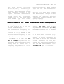
FUNDAMENTALS OF TELEGRAPH TRANSMISSIONS
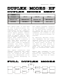
DUPLEX MODES HF
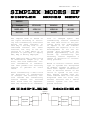
SIMPLEX MODES HF
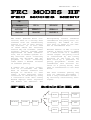
FEC MODES HF
PAGE
PAGE
PAGE
PAGE
PAGE
PAGE
PAGE
PAGE
PAGE
PAGE
PAGE
PAGE
PAGE
PAGE
PAGE
PAGE
1
1
2
3
3
4
5
6
8
11
13
15
19
25
26
27
CONTENTS - PAGE 2
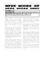
MFSK MODES HF
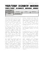
VHF/UHF DIRECT MODES
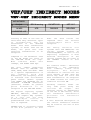
VHF/UHF INDIREC MODES
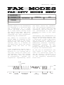
FAX MODES
CARRIER MODULATION PROCEDURES
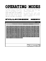
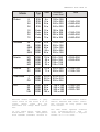
BAUDRATES, SPEED AND CARRIER MODULATION
PAGE
PAGE
PAGE
PAGE
PAGE
PAGE
VIDEO FULL SCREEN MENU
MAIN MENU
MODES FROM A TO Z
PAGE 1
PAGE 2
PAGE 3-91
A
B
C
D
E
F
G
H
I
M
N
P
R
S
T
v
W
Z
28
29
30
31
32
33
ACARS, ALIS, ALIS-2, ARQ-E, ARQ-E3, ARQ-N, ARQ-M2-242, ARQ-M2-342,
ARQ-M4-242, ARQ-M4-342 ARQ6-90, ARQ6-98, ASCII, ATIS, AUTOSPEC
BAUDOT, BULG-ASCII
CCIR, CCITT, CIS-11, CIS-14, CIS-36, CODAN SELCAL, COQUELET-8, COQUELET-13, QUOQUELET-80, CW-MORSE
DGPS, DUP-ARQ, DUP-ARQ-2, DUP-FEC-2, DTMF
ERMES, EEA, EIA, EURO
FEC-A, FELDHELL, FMS-BOS
GMDSS/DSC-HF AND VHF, GOLAY, G-TOR
HC-ARQ, HNG-FEC
ICAO SELCAL, INFOCALL
METEOSAT, MPT1327
NATEL, NOAA-GEOSAT
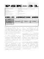
PACTOR, PACKET-300/600, PACKET-1200, PACKET-9600, PCM-30, PICCOLOMK6, PICCOLO-MK12 POCSAG, POL-ARQ, PRESS- FAX, PSK-31
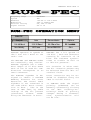
RUM-FEC
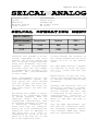
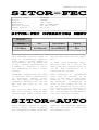
SELCAL ANALOG, SI-ARQ, SI-FEC, SI-AUTO, SITOR-ARQ, SITOR-FEC, SITORAUTO, SPREAD-11, SPREAD-21, SPREAD-51, SSTV, SWED-ARQ
TWINPLEX
VDEW
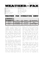
WEATHER-FAX
ZVEI-VDEW, ZVEI-1, ZVEI-2
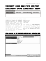
MENU ANALYSIS HF
MENU ANALYSIS VHF
MENU SIGNAL ANALYSIS HF
MENU SIGNAL ANALYSIS VHF/UHF
FSK ANALYSIS HF
SIGNAL TWINPLEX
DIRECT FSK ANALYSIS VHF/UHF
INDIRECT FSK ANALYSIS VHF/UHF
PSK SYMBOL RATE MEASUREMENT AND PSK PHASE PLANE
HF CODE ANALYSIS
DIRECT CODE ANALYSIS VHF/UHF
INDIRECT CODE ANALYSIS VHF/UHF
VHF/UHF SELCAL ANALYSIS
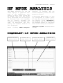
HF MFSK ANALYSIS
REAL-TIME FFT
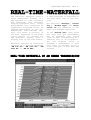
REAL-TIME-WATERFALL
PAGE
PAGE
PAGE
PAGE
PAGE
PAGE
PAGE
PAGE
PAGE
PAGE
PAGE
PAGE
PAGE
PAGE
PAGE
PAGE
1
1
2
2
2
3
4
6
8
12
15
18
20
22
24
27
CONTENTS - PAGE 3
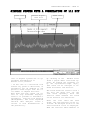
REAL-TIME-SONAGRAM
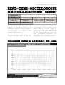
REAL-TIME-OSCILLOSCOPE
AUTOCORRELATION
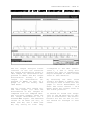
HF BIT ANALYSIS
BIT LENGTH ANALYSIS HF
RAW V1-DATA ANALYSIS HF
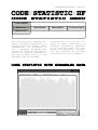
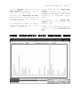
CODE STATISTICS HF
SETUP FUNCTIONS
REMOTE CONTROL
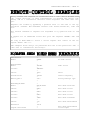
REMOTE-CONTROL EXAMPLES
GLOBAL REMOTE COMMANDS
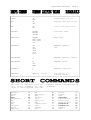
SHORT COMMANDS
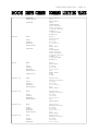
REMOTE COMMANDS MODES
LOADING OF THE W4100DSP SOFTWARE VIA REMOTE-CONTROL
PAGE
PAGE
PAGE
PAGE
PAGE
PAGE
PAGE
PAGE
PAGE
PAGE
PAGE
PAGE
PAGE
PAGE
28
29
31
34
39
42
44
46
48
50
52
53
54
63
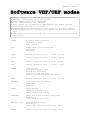
TECHNICAL SPECIFICATIONS HARDWARE
VIDEO - DEMODULATOR - INTERFACES
TECHNICAL DATA DSP DEMODULATOR
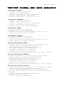
SOFTWARE HF MODES
HF SIGNAL AND DATA ANALYSIS
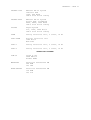
SOFTWARE VHF/UHF MODES
VHF/UHF SIGNAL AND DATA ANALYSIS
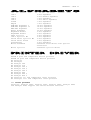
ALPHABETS - PRINTER DRIVERS
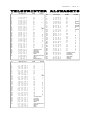
TELEPRINTER ALPHABETS
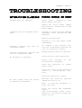
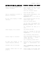
TROUBLESHOOTING
FUSE REPLACEMENT
SIGNAL INTERFERENCES
CONDITIONS OF SALE
TERMS OF DELIVERY AND PRICES
LITERATURE
PAGE
PAGE
PAGE
PAGE
PAGE
PAGE
PAGE
PAGE
PAGE
PAGE
PAGE
PAGE
PAGE
PAGE
PAGE
1
2
4
6
12
14
16
18
19
21
23
23
24
25
25
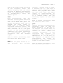
INSTALLATION - PAGE 1
Before connecting any peripheral
equipment to the data and telegraph analyzer W4100DSP all devices should be powered off to
avoid damages. Experience shows
that damage often occurs due to
heavy static build-ups. Because
of this the metal case of the
W4100DSP
which
is
grounded
through the power mains should
be touched before installation
of any peripheral equipment.
Connect the included power cable
to a 230V/50Hz power mains outlet and to the plug marked "AC
230 VOLT 50/60 Hz". A 1A mains
fuse is located in a drawer in
the upper part of the combined
mains connector and power on-off
switch. The W4100DSP is also
available in a 115 Volts version
with a 2A mains fuse.
Connect a VGA or multi sync
colour monitor to the rear DB-15
plug marked "VGA MONITOR". A
matching cable is included in
the complete monitor package. If
an older type EGA plug is used,
an adapter (DB-9 female to DB-15
male) may be obtained in most
computer stores.
The VGA video signal of the
W4100DSP is compatible with PCATs having a resolution of 640 x
480 pixels. The red, green and
blue color signals are analog.
Please notice
the paragraph
"Setting of the DIP switches" of
this
section,
where
the
selection of H-sync and V-sync
polarity is explained.
Practically any monitor may be
adapted
to
the
interface.
Several brands of monitors have
been tested.
Some PHILIPS and EIZO monitors
have been tested. These models
comply to the MPR II or TCO-92
radiation standard.
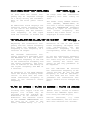
INSTALLATION - PAGE 2
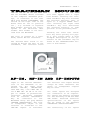
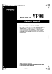
The A4 TrackMan Mouse included
in the complete W4100DSP package, is connected to the rear
DB-9 plug marked "TRACKMAN". The
switch on the right side of the
mouse must be set in position
"3" , e.g. PC-mode or LogiTech
data format. Position "2" corresponds to the Microsoft data
format. This format is not utilized with the W4100DSP.
The plug is pinned as a standard, serial RS-232 interface.
The desired menu field is selected by moving the ball of the
trackball, the selected field
will then appear with a light
blue border. Pressing the lefthand trackball key will activate
the selected function. This is
equal to a keypad ENTER function. Pressing the right hand
trackball key will deactivate
the selected function or take
you back to the preceding menu.
Pressing the lower left trackball key twice quickly will popup a full screen menu. A more
in-depth description of the operation of the trackball may be
found in the "INTRODUCTION" section of this manual.
Select
function
Leave
function
Full screen menu
with double click
Input to the various demodulators of the W4100DSP is obtained via the input plugs
marked
"AF-IN",
"AF/HF-IN",
"455 KHZ IN", "10.7 MHZ IN" or
"21.4 MHZ IN". An HF or IF output is common in professional
receivers. Receivers equipped
with an internal demodulator
may
be
connected
to
the
W4100DSP using the plug marked
"EXTERN DEMODULATOR". The line
or loudspeaker output of the
receiver is connected to the
"AF-IN" inputs. If available
the receiver line output should
always be used. Otherwise the
phone or loudspeaker outputs
may be used.
All other inputs are designed
for connection to IF outputs.
All inputs are equally suitable
for the decoding of HF and VHF/
UHF modes. Detailed technical
specifications of the inputs
may be found in the appendix
"TECHNICAL SPECIFICATIONS".
The sensitivity of all inputs
INSTALLATION - PAGE 3
is software selected using the
"SETUP\GAIN" or the “DEMODULATOR\GAIN" menu, which is included in all mode menus. The 0100 range corresponds to an input sensitivity of 0.01 Vpp to 5
Vpp for maximum drive.
The translation frequency is adjusted by using the "SETUP FUNCTIONS \ DEMODULATOR" menu or the
"DEMODULATOR \ TRANSLATION" menu
included in most mode menus. The
W4100DSP employs high stability
DDS frequency generation, the
smallest step being 1 Hz on all
inputs. In addition to the analog inputs the W4100DSP also has
a digital input which conforms
to
the
RACAL
data
format
("DIGITAL IN"). The sensitivity
of this input is fixed at 0 dB
so receiver output must be adjusted to this level.
The front plate level indicator
("LEVEL") indicates the input
signal level. When the red part
of the indicator is turned on,
the A/D converter is overloaded
and the quality of the demodulator output is decreased.
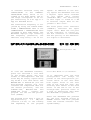
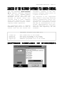
Write-protect tab
To load the W4100DSP software,
place the enclosed 3 1/2" disk
in the floppy drive. The file
format is PC-compatible and the
files may be freely copied using
any PC-AT 3 1/2" disk drive. The
MASTER.ARJ or APPLIK.GZ (for new
boot-program version 4.2) file
contains the compressed data for
the master processor, and the
LOADER.LOD,
MASTER.LOD
and
SLAVE.LOD files
contain the
program for the two DSP processors (SLAVE).
The program files have a
approximately
1.5
(version 3.4.05) so the
and expanding of the
size of
MBytes
loading
program
will take about 8 1/2 minutes.
It is important that the disk
write-protect
tab
always
be
placed in the write-protect position which is the case when
both square holes of the rear
side of the disk are open. The
disk may then remain in the disk
drive. If the tab is not in the
write-protect position there is
a risk of destroying data when
the W4100DSP is powered off.
After the W4100DSP has powered
up, the boot program stored in
EPROMs starts. The boot program
loads the runtime software into
system memory.
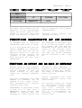
INSTALLATION - PAGE 4
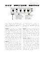
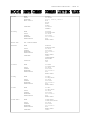
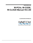
Standard Monitor
Development system
Standard Video Synch
VSynch negative
HSynch negative
Compaq VGA Monitor
Program from floppy
CSynch
VSynch positive
HSynch positive
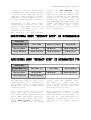
After removing the W4100DSP rear
cover plate marked "PC XT/AT
HOST INTERFACE/DIP SWITCHES" a
bank of five DIP-switches is accessible.
be effective after a device reset. This may be performed by
pressing the "LOAD-RESET" key or
powering the W4100DSP down and
up again.
SWITCH 1 switches on a Compaq
type of VGA monitor. This monitor has a displacement of the
horizontal position, but does
not have a potentiometer for
correction. For most other types
of monitors this switch must be
in position ON. If this switch
is left in its OFF position some
multisync monitors will turn
dark after booting has been completed. The video signal of the
boot loader always follows the
H-synch switch position.
SWITCH 3 changes the mode of the
video sync signals. Most monitors employ separate H- and VSync
signals,
and
thus
the
switch must be left ON. However
certain industrial monitors expect both sync signals to be
available on the H-line. For
these monitors the switch must
be OFF.
SWITCH 2 indicates to the processor whether the program will
be loaded from the floppy drive
or the PC-Host interface. For
loading from the floppy drive
the switch must be in position
OFF. For program development the
switch must be ON. Thus software
may be directly downloaded from
a PC-AT. Any changes will only
SWITCH 4 and 5 provide a toggle
of the polarity of the sync signals. The manufacturers of monitors have not been able to agree
to a standard video sync polarity. However modern monitors
will often be able to automatically sense the polarity. The
correct position of switch 4 and
5 must therefore be found depending of the type of monitor
used. As most monitors employ
negative sync signals switches 4
and 5 may be left ON.
INSTALLATION - PAGE 5
This 40 pin plug placed next to
the bank of dip-switches provides for directly downloading
of software from a PC-AT. For
this purpose a PC add-on card
manufactured by WAVECOM is necessary. This interface makes
possible simple and efficient
software development. The add-on
card is only available with the
source code. To avoid damages,
the PC and W4100DSP should always be powered on or off simultaneously.
If an external demodulator is to
be connected then this input
must be used.
This input is activated using
t h e
" S E T U P
F U N C TIONS\DEMODULATOR" menu.
Connect ground to pin 5, V1 data
to pin 3, and F7B V2 data to pin
4. The minimum input level is
TTL level (LO = 0.8 V, HI = 2.4
V) and the maximum is RS-232C
level (LO = -12 V, HI = + 12 V).
Note that utilizing this facility
will
disable
certain
W4100DSP functions. Thus this
input should be employed for
special purposes only.
All IF inputs are designed for
connection to receiver IF outputs. All inputs are equally
suitable for the decoding of HF
and VHF/UHF modes.
ble. The IF input signals are
directly converted and decoded
in the W4100DSP. Signals within
an input voltage range from 10
mVpp to 5 Vpp are decoded without errors. Professional receivers produce a sufficient IF
level, whereas amateur equipment
will often need to be modified.
The POCSAG, INFOCALL and GOLAY
modes employ direct frequency
modulation. An error free decoding is only possible at IF
level.
The IF output of the receiver
should be directly connected to
the corresponding W4100DSP IF
input using a BNC-BNC coax ca-
The digital PCM input of the
W4100DSP utilizes a standard interface. Input must conform to
the digital HDB3 signal format.
This input is compatible with
the output interface of satel-
The bargraph TUNING indicator
serves as a tuning aid. Correct
tuning is achieved if the signal
is
displayed
symmetrically
around the bargraph center.
lite
demodulators
and
ISDN
lines. The PCM input is employed
when decoding 2.048 Mb/s PCM
signals. Via the DSP processors
a channel is selected and output
to a digital-analog converter.
INSTALLATION - PAGE 6
The "DIGITAL-IN" input of the
W4100DSP utilizes a standard interface. Modern digital HF and
VHF-UHF receivers employing DSP
(Digital
Signal
Processing)
techniques have direct digital
output interfaces. The W4100DSP
decodes this input signal. The
interface conforms to the RACAL
standard.
The
AF-OUT
output
of
the
W4100DSP utilizes a standard interface. It has a 12-bit D/A
(digital-analog) converter fol-
lowed by a low pass filter. The
output may be the AF signal of a
PCM channel or it may be used as
an output for test signals.
INSTALLATION - PAGE 7
At serial interface #1 data is
available in serial format. This
interface is software configured.
The "REMOTE CONTROL" RS-232 interface is used for remoting the
W4100DSP. If a printer is connected to a serial interface it
is necessary to ensure that compatibility exists between sending and receiving equipment.
The following parameters must be
in agreement:
Baudrate: The baud rate is a
measure of the serial interface
data transfer speed. In the
"SETUP FUNCTIONS\Serial #1" menu
the following speeds may be selected:
300, 600, 1200, 2400, 4800, 9600
or 19200 baud
19200 baud is recommended as a
standard speed for "SERIAL #1".
For the "REMOTE CONTROL" interface the baud rate should not
exceed 9600 baud.
Data bits: 7 or 8 data bits may
be selected giving character
sets of 128 or 256 characters.
For example the ISO code table
contains the German national
characters ä, ö, ü within the
first 128 bit combinations (123,
124, 125 decimal). However, the
IBM PC code table defines these
characters as decimal 132, 148,
129 and double s as 225.
Thus to print the national characters of non-English languages
the interface must be set to 8
data bits.
Stop bits: 1 or 2 stop bits may
be selected. One stop bit is
normally adequate.
Parity: The parity function provides a degree of error detection and correction. As the
printer cannot ask for repetition of characters received in
error, parity control may be
skipped ("No parity"). Options
are NO, EVEN and ODD parity. No
parity is recommended as standard.
Remote address 0-99: The address
of the W4100DSP when remotely
controlled may be set in the
"SETUP\REMOTE
CONTROL"
menu.
Value is 0.
Output to serial output #1 is
permanently on and is not controlled by the "PRINT-ON" or
"PRINT-OFF" functions. The parallel interface may be switched
on and off using the "PRINT-ON"
and "PRINT-OFF" functions.
Note that, in all fax modes,
output is NOT sent to the serial
interface due to the huge amount
of data contained in fax pictures.
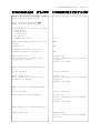
INSTALLATION - PAGE 8
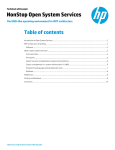
Printer
W4100DSP
25-Pol D-SUB RS232
9-Pol D-SUB SERIAL RS232 #1
Transmit Data (TXD)
2
2
Receveice Data (RXD)
Receveice Data (RXD)
3
3
Transmit Data (TXD)
Ground (GND)
5
5
Ground (GND)
20
6
Data Set Ready (DSR)
8
Clear to Send (CTS)
Data Terminal Ready (DTR)
PC/AT
9-Pol D-SUB RS232
W4100DSP
9-Pol D-SUB RS232 #1
Receive Data (RXD)
2
2
Receive Data (RXD)
Transmit Data (TXD)
3
3
Transmit Data (TXD)
Ground (GND)
5
5
Ground (GND)
Data Terminal Ready (DTR)
4
6
Data Set Ready (DSR)
8
Clear to Send (CTS)
A
terminal
emulator
program
loaded in the PC/AT must control
the transfer of data from the
serial interface. This program
handles transfer of data to the
PC and the subsequent storage on
a floppy or hard disk. Afterwards the ASCII files may be
edited using an editor program.
Many shareware terminal programs
are available in the PC market.
A program having a freely definable character map is recommended. This will enable use of
national characters like ä,ö or
ü.
INSTALLATION - PAGE 9
The standard Centronics interface is used for connecting a
parallel printer.
The printer type may be software
selected using the menus "SETUP
FUNCTIONS",
"PRINTER",
and
"PRINTER TYPE".
Centronics printer cable length
should not exceed 2m. The con-
Centronics Printer
36-pin connector
figuration of the DB-25 connector is identical to standard PC
convention, and all standard
computerprinter cables may be
utilized.
The print screen-function is at
present implemented for the HP
PAINTJET, HP 500C, HP 550C, HP
560C, HP 660C and HP 850C.
W4100DSP
25-Pol D-SUB connector
Strobe
1
1
Strobe
Data 1
2
2
Data 1
Data 2
3
3
Data 2
Data 3
4
4
Data 3
Data 4
5
5
Data 4
Data 5
6
6
Data 5
Data 6
7
7
Data 6
Data 7
8
8
Data 7
Data 8
9
9
Data 8
Acknlg
10
10
Acknlg
Busy
11
11
Busy
PE
12
12
PE
SLCT
13
13
SLCT
Autofeed
14
14
Autofeed
Error
32
15
Error
Init
31
16
Init
Slct-In
36
17
Slct-In
19
18
bis
30
bis
Ground
25
Ground
INSTALLATION - PAGE 10
5
1
2
3
13
14
1
6
10
15
Analog red
Analog green
Analog blue
HSynch
VSynch
Ground
5, 6, 7, 8, 10, 11
11
Connector
Signal
Function
Pin
Pin
Pin
Pin
Analog red signal
Analog green signal
Analog blue signal
Horizontal synch signal
Analog 0.7 VPP positive
Analog 0.7 VPP positive
Analog 0.7 VPP positive
Synch 31.5 KHz / TTL-Level
positive or negative
Synch 60 Hz / TTL-Level
positive or negative
1
2
3
13
Pin 14
Vertical synch signal
Pin 5,6,7
Pin 8,10,11
Ground
Ground
1
2
6
3
7
4
8
2
3
4
5
6
7
8
5
9
Receive data (RXD)
Transmit data (TXD)
Data terminal ready (DTR)
Ground
Data set ready (DSR)
Request to send (RTS)
Clear to send (CTS)
Connector
Signal
Function
Pin
Pin
Pin
Pin
Pin
Pin
Pin
Pin
Pin
RXD
TXD
DTR
GND
DSR
RTS
CTS
NC
NC
Receive Data (Received Data)
Transmit Data (Transmitted Data)
Data Terminal Ready
Ground
Data Set Ready
Request To Send
Clear To Send
not connected
not connected
2
3
4
5
6
7
8
1
9
INSTALLATION - PAGE 11
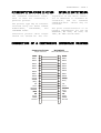
1 3 5 7 9 11 13 15 17 19 21 23 25 27 29 31 33 35 37 39
2
40
PIN 2 - 40 GROUND
Connector
Signal
Function
Pin
Pin
Pin
Pin
Pin
Pin
Pin
Pin
Pin
Pin
Pin
Pin
Pin
Pin
Host Data 0 to
Host Data 7
HWrite
HRead
HFS0
HFS1
HLDS
HUDS
HINT
HRDY
HEN
HDIR
HCS
EXTRESET
8 Bit data bus from/to PC
1 to
15
17
19
21
23
25
27
29
31
33
35
37
39
1
2
6
3
7
Host Write Strobe
Host Read Strobe
Host Function Select 0
Host Function Select 1
Host Lower Data Select
Host Upper Data Select
Host Interrupt
Host Ready
Host Enable Strobe
Databus Direction
Host Chip Select
Extern Reset / Power On
Control
4
8
5
3
Extern V1 Data
4
Extern V2 Data
5
Ground
9
Connector
Signal
Function
Pin 3
Extern V1 Data
Pin 4
Extern V2 Data
Pin 5
Ground
Input for external
demodulator
Level TTL up to +/- 12 Volts
RS232
Input F7B Signal
Level TTL up to +/- 12 Volts
RS232
Ground
INSTALLATION - PAGE 12
1
2
6
3
7
4
8
5
9
2
3
4
5
6
7
8
Receive data (RXD)
Transmit data (TXD)
Data terminal ready (DTR)
Ground
Data set ready (DSR)
Request to send (RTS)
Clear to send (CTS)
Connector
Signal
Function
Pin
Pin
Pin
Pin
Pin
Pin
Pin
Pin
Pin
RXD
TXD
DTR
GND
DSR
RTS
CTS
NC
NC
Receive Data
Transmit Data
Data Terminal Ready
Ground
Data Set Ready
Request To Send
Clear To Send
Not connected
Not connected
2
3
4
5
6
7
8
1
9
13
1
25
14
Connector
Signal
Function
Pin
Pin
Pin
Pin
Pin
Pin
Pin
Pin
Pin
Pin
Pin
Pin
STROBE
DATA 1 to
DATA 8
ACKNLG
BUSY
PE
SLCT
AUTOFEED
ERROR
INIT
SLCT-IN
GROUND
Data ready command for printer
Printer data parallel
Printer data parallel
Confirmation-signal data takeover
Confirmation-signal for reception readiness
no paper when HIGH
Confirmation-signal ON-LINE when HIGH
automatic line feed when LOW
Printer in Error when LOW
New initialisation of the printer when LOW
DC1/DC3 Code active when HIGH
Ground
1
2 to
9
10
11
12
13
14
15
16
17
18-25
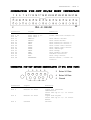
INSTALLATION - PAGE 13
5
4
9
3
8
2
7
1
6
Connector
Signal
Function
Pin
Pin
Pin
Pin
Pin
Pin
Pin
Pin
DATAEXT+
DATAEXTCLKEXT+
CLKEXTFSEXT+
FSEXTGND
NC
Serial data, balanced +
Serial data, balanced Bit clock, balanced +
Bit clock, balanced Frame sync, balanced +
Frame sync, balanced Ground
Not connected
2
7
1
6
4
9
5
3 and 8
5
4
9
Connector
Signal
Input PCM:
Pin 6
PCM+
Pin 7
PCMPin 1,2,3,8,9 GND
3
8
2
7
1
6
Function
Serial data, balanced +
Serial data, balanced Ground
Input SERIAL (V1/V2 is Strobe):
Pin 4
SERDAT
Serial data
Pin 5
SERSTR
Bit clock
Pin 1,2,3,8,9 GND
Ground
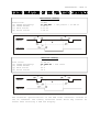
INSTALLATION - PAGE 14
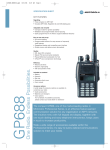
Horizontal Timing
Pixelclock:
(a) HSYNC Frequency:
(b) HSYNC Width:
(c) Back Porch:
(d) Front Porch:
25 MHz
31.565 KHz
2.08 us
2.72 us
1.28 us
/ 792 pixels = 31.68 us
b
d
HSYNC
a
c
HBLANK
Vertical Timing
Line cross:
(e) VSYNC Frequency:
(f) VSYNC Width:
(g) Back Porch:
(h) Front Porch:
31.68 us
59.7843 Hz / 528 lines
2 Z
30 Z
16 Z
f
h
VSYNC
e
g
VBLANK
The technical specifications of the VGA video interface conform to
the PC standard. The timing relations shown above may however be
useful when selecting a VGA LCD display.
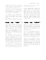
INTRODUCTION - PAGE 1
After loading of the W4100DSP
application software the WAVECOM
logo with the software version
is displayed. After this task
has been completed the main menu
appears in the lower left part
of the screen.
MAIN MENU
HF-Modes
VHF/UHF-DIR
VHF/UHF-IND
Satellite-Modes
Setup Functions
The operation of the W4100DSP is
completely controlled by a menu
system which in turn is controlled by a trackball or by
cursor keys. The trackball consists of a moving ball and three
keys. Moving the ball will take
the operator from one field of
the menu to another field. A selected field will appear with a
light blue border line. Clicking
the upper left key will activate
a field with a light blue border, clicking the upper right
key will deactivate it.
If the operation of the equip-
ment is done using the front
panel "UP", "DOWN", "LEFT", and
"RIGHT" cursor keys, these keys
are equivalent to moving the
trackball in the same directions.
The
"ENTER"
key
is
equivalent to the left trackball
key and activates a function. If
the “ESCAPE” key is pressed the
function is deactivated, this
key being equivalent to the
right
trackball
key.
Double
clicking the lower left trackball key will display a full
screen menu.
Select
function
Full screen menu
with double click
Leave
function
INTRODUCTION - PAGE 2
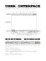
The screen is sub-divided into four sections: system window, text
and graphics window, operator window and demodulator window.
Active mode
Baudrate
Option field 1
Signal polarity
System status
Option field 2
Data and time indication
08-02-2000
14:11:17
Text and graphics field
Operator window
MAIN MENU
HF-Modes
Setup Functions
VHF/UHF-Ind
VHF/UHF-Dir
Satellite-Modes
-495 Hz
DSP
Intern
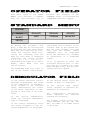
Operator fields
Active demodulator
System messages' field
Field 1
SITOR-ARQ
Field 2
100.0
Field 3
Bd
Trans.Frq.
Active data input
Active operator field
(blue bordered)
Active operator level
495 Hz
1700 Hz
Field 4
Translation frequency
Field 5
Phasing
Demodulator
window
Shift 830 Hz
0 Hz
AF
Aktive shift
Tuning indicator limits
Centre frequency
Tuning indicator
Field 6
Signal input
Field 7
08-02-2000
14:11:17
The system window displays information about the status of the
software.
Field
Field
Field
Field
Field
1:
2:
3:
4:
5:
Mode indication
Baud rate indication
Miscellaneous messages
Signal polarity indication (N = normal, I = inverted)
Signal and system state (e.g. Phasing, Synch, Traffic or
Idle)
Field 6: Miscellaneous messages
Field 7: Time and date indication
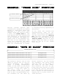
INTRODUCTION - PAGE 3
Each menu field of the "MAIN
MENU" will activate a submenu
when the left trackball key is
pressed. For instance if the
STANDARD field is activated the
"STANDARD" menu will appear.
STANDARD
Analysis
SITOR-AUTO
SITOR-ARQ
SITOR-FEC
BAUDOT
ASCII
CW-Morse
Packet-300
PACTOR
By moving the trackball once
more, a mode may be selected and
by pressing the left hand trackball key this mode may be activated. For instance after activating the SITOR-ARQ mode the
menu for this mode is displayed
containing the fields "Signal
A n a l y s i s " , " A u t o " ,
"Demodulator","Options","100.0
Baud",
"96.0
Baud
var"
and
"Force letter".
The SITOR-ARQ mode will start if
one of the fields "100.0 Baud",
In the tuning indicator field a
bargraph is displayed. The width
of the indication is automatically related to the selected
shift. Additionally the limits
of the shift indication is displayed on each side of the indicator.
In
the
“Active
Demodulator”
field the selected demodulator
type is displayed.
In the “Centre Frequency“ field
the centre frequency of the selected demodulator is displayed.
"96.0 Baud var" or "Auto" is activated. Then in the system window the mode "SITOR", the baud
rate
and
the
system
status
"PHASING"
will
be
displayed
while the software will attempt
to synchronize on a SITOR-ARQ
signal.
If it is desired to leave the
activated function this is simply done by clicking the right
hand trackball key, and the preceding menu will appear.
In the “Active Shift” field the
amount of shift is displayed.
In
the
“Active
Data
Input”
field, internal or external demodulator is indicated.
The
“Translation
Frequency”
field indicates the selected
translation frequency.
The “Signal Source” field indicates whether the AF, HF, 455
kHz, 10.7 MHz or 21.4 MHz source
is selected.
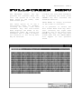
INTRODUCTION - PAGE 4
The W4100DSP offers two approaches for software menu control. One option is to use the
menu field in the lower, left
hand screen part.
The other option is to use a
full-screen
menu
by
doubleclicking the lower, left hand
trackball key. The full-screen
menu displays the modes in alphabetical order. By turning the
trackball ball a mode, an analysis function or the set-up menu
may be selected.
Clicking the left hand trackball
key or pressing the front plate
“ENTER” key will activate the
selected function.
"AUTO MODE" is always activated
if this mode is available.
It is possible to select the
full screen menu from any function. Pressing the right hand
trackball key or the front plate
ESCAPE key will clear the full
screen menu and the "MAIN MENU"
will appear in the operator
field.
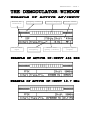
INTRODUCTION - PAGE 5
Active demodulator
Display limits
Active data
input
Translation
frequency
Tuning display
Centre frequency (Centre)
Actual shift
Signal input
(Input)
INTRODUCTION - PAGE 6
The demodulator has its own
message field placed in the
lower, right hand screen area.
The upper part of this field is
assigned to a bargraph tuning
indicator. The magnitude of the
indication
is
automatically
related to the instantaneous
frequency
shift.
Additionally
the lower and upper limits of
the shift are displayed on each
side of the bargraph.
In the left field the active
demodulator is indicated. Nine
different
demodulators
are
available.
DSP-MODE:
The DSP-mode utilizes an I/Q
demodulator
(Hilbert
transformation).
The
received
signal is split into an in-phase
component
and
a
quadrature
component. Next an amplitude
normalization takes place. The
resultant signal is used for the
frequency
conversion.
This
method is characterized by a
linear relationship between the
received
frequency
and
the
output
voltage
of
the
demodulator.
The DSP demodulator has a good
signal -to- nois e
rat io
and
yields very good results under
most conditions.
MARK-SPACE:
The
mark-space
demodulator
processes
the
two
keying
frequencies. These are fed to
two phase linear FIR filters and
the
amplitude
is
then
calculated.
The
mark-space
demodulator
exhibits
an
extremely good noise distan and
should be used for all FSK modes
utilizing a speed of less than
300 Baud.
FFSK and GFSK:
Depending on the mode the FFSK
and
GFSK
demodulator
is
automatically
selected.
Basically
this
demodulator
utilizes
the
I/Q
principle
(Hilbert). However, filters are
adjusted
to
accomodate
the
special demands in these modes.
MFSK:
This
demodulator
handles
multifrequency signals. Filters
are switched in on the various
frequencies of the signal and
the amplitude is then calculated
for each frequency. Next the
amplit udes
ar e
eva luat ed.
Simultaneous tones may also be
demodulated. Depending on the
number of tones used the filters
are configured as phase linear
FIR filters or as IIR filters.
The SNR is the same as for the
mark-space demodulator.
CW-MORSE:
The CW-demodulator utilizes a
steep FIR filter and automatic
amplitude
control.
The
AGC
attack
time
may
adjusted
according to conditions. The
filter response may be set to
"Slow", "Normal" or "Fast". This
demodu lato r
p roduce s
h igh
quality
CW
decoding.
It
is
important
to
select
the
appropriate
receiver
AGC
response ("Normal" or "Slow").
AM FAX:
Satellite weather charts are
transmitted
using
AM.
This
demodulator also uses the I/Q
method. However, the amplitude
of the signal is calculated
instead of its frequency.
In the centre field of the
demodulator window the centre
frequency to which the W4100DSP
has been adjusted is displayed
INTRODUCTION - PAGE 7
and in the right field the value
of the frequency shift. The
centre frequency and the shift
may both be manually adjusted by
using the "DEMODULATOR" submenu
or
automatically
using
the
"AUTO" option.
DPSK:
With
differential
PSK
the
absolute carrier phase cannot be
used for data recovery as is the
case with BPSK and QPSK. To
decode multiphase DPSK (up to
16DPSK) the input signal is
mixed with a complex, phase
regulated reference signal. The
resulting data reduced signal is
then filtered in a low pass
filter. In the following phase
comparator the phase difference
is
calculated
from
the
integrator
and
the
delayed
signal.
DPSK is almost exclusively used
for short wave data links.
BPSK:
BPSK has two phase shifts at +/180
degrees.
For
carrier
recovery a Costas loop is used.
A Costats loop is a PLL with a
special phase comparator which
removes the payload data from
the PLL loop. Then the input
signal
is
downconverted
to
baseband by mixing the carrier
in a complex mixer, and the
resulting signal is the data
signal.
BPSK is almost exclusively used
for satellite data links.
QPSK:
Carrier recovery is mandatory to
demodulate QPSK. As QPSK has
phase shifts at +/- 45 and +/135 degrees the signal must be
suared two times to produce a
carrier
at
four
times
the
original
frequency.
A
PLL
recovers
the
carrier
in
frequency
and
phase
with
ambiguities at +/- 90 and +/180 degrees. A complex mixer
downconverts
the
signal
to
baseband,
and
the
resulting
signal is the data signal.
QPSK is almost exclusively used
for satellite data links.
INTRODUCTION - PAGE 8
Demodulator
Select Mode
Shift
Center Frq.
V1/V2 is intern
Input
Gain
Translation Frq.
Nearly all modes have a “DEMODULATOR” submenu. Using this
menu the demodulator settings
may be changed. This will not
influence an active mode or stop
it. An exception is made in
"Select Mode" when changing demodulator type. Due to the difference in signal propagation
time for the various demodulators synchronization may be lost
depending on the selected mode.
The mode must then be restarted
by selecting a fixed or variable
baud rate.
Using this menu field either the
DSP or the Mark-Space mode may
be
selected.
The
FFSK-GFSK,
MFSK, CW and AM-FAX demodulators
are tied to the corresponding
modes and are automatically selected
menu
field.
The
"Selected Mode" is not displayed
in this modes.
After activating the menu field
the active demodulator type is
displayed.
When
moving
the
trackball ball, the demodulator
types will appear. The selected
demodulator is activated clicking the left hand trackball key.
Clicking the right hand trackball key will leave the function
without any changes.
In this submenu the shift may be
manually adjusted in steps of 1
Hz.
value, and moving the ball to
the left or right (cursor keys
“LEFT” or “RIGHT”) will move the
decimal position.
The trackball ball or the front
plate cursor keys perform two
functions. Moving the ball forwards or backwards (cursor keys
“UP” or “DOWN”) will change the
When entering AUTO MODE measurements are stopped immediately to
prevent AUTO MODE from overwriting the manually selected values.
Depending on the active mode the
shift range is 50 Hz - 3500 Hz
(HF modes, indirect modes) or 50
Hz to 16000 Hz (direct modes).
INTRODUCTION - PAGE 9
In this menu the center frequency may be adjusted insteps
of 1 Hz by moving the trackball
ball or the front panel cursor
keys.
An additional field displays the
effective center frequency which
is the sum of the selected center frequency and the translation frequency. If the input
from the receiver is within the
Adjusting the translation frequency and the centre frequency
will adapt the W4100DSP input
frequency to the frequency of a
receiver IF output.
The minimum translation frequency resolution available with
the W4100DSP is 1 Hz. The effective centre frequency is the sum
of the translation frequency and
the centre frequency. The function is similar to the mixing of
the signal frequency and BFO of
a receiver.
An exception is the FFSK demodulator for direct frequency modulation. In this case the indicated translation frequency is
equal to the effective centre
frequency.
Clicking this toggle field the
digital
bit
stream
may
be
switched from the internal demodulators to an external demodulator. The external source
on the “EXTERN DEMODULATOR” input must be at least at TTL
level, maximum being +/- 12 V
AF range then the translation
frequency will most likely be
zero.
The modes using DIRECT modulation (POCSAG, PACKET-9600) do
not have a centre frequency, and
thus the TRANSLATION frequency
setting is equal to the effective
center
frequency.
The
"Center Frq." menu field is not
displayed in these modes.
Selection of one of the three
fixed frequency IF-inputs will
also
automatically
set
the
translation frequency to the
corresponding value and display
it.
To use the translation frequency
method has the advantage, that
its value only has to be entered
once leaving the center frequency as the only parameter to
be adjusted.
For the “HF-1000” HF receiver
the translation frequency is adjusted 453.300 Hz and the BF0
frequency to 1700 Hz (CW mode).
In auto mode and all other adjustments the translation frequency should not be changed any
more.
(RS232 level). “V1/V2 is Strobe”
selects the “SERIAL” input function using the PCM IN plug.
Various functions, e.g. baud
rate measurement, are not available with external bit streams.
INTRODUCTION - PAGE 10
Input
AF
HF
IF455 KHz
IF21.4 MHz
Digital 3791
PCM
IF10.7 MHz
This menu field connects the demodulator to the corresponding
input. The active input is displayed in the lower right hand
field. The function of these in-
puts is detailed in the chapter
"INSTALLATION".
In CW-MORSE mode an additional
“Bandwidth” menu field is found.
The bandwidth is adjustable from
50 Hz to 1200 Hz. Normal values
are between 500 and 800 Hz.
Bandwidths below 200 Hz make the
tuning of the receiver difficult. For keying speeds above
300 BPM the filter bandwidth
must be increased to 800 - 1200
Hz.
It is a well-known fact that decoding CW-MORSE is difficult.
Thus in this mode the DSP demodulator serves as a high selectivity digital filter. Adjustment of the bandwidth is
done activating the menu field
"Bandwidth".
Weather satellite fax transmissions consist of an AM modulated
carrier. Because of this the
signal strength of the input
signal will influence demodulation.
Utilizing "AM-GAIN" and "AMOFFSET" the W4100DSP may be
adapted to the signal source.
Both adjustments will mutually
influence each other.
"AM-OFFSET" is adjustable within
a range of 0 to 2047. With a
"METEOSAT" signal present "AMOFFSET" is adjusted until the
bargraph is clearly driven into
"Digital
3791"
selects
"DIGITAL-IN" input.
the
saturation. Next "AM-GAIN" is
adjusted to place the shift symmetrically around the centre.
The range of adjustment is between 0 and 100.
Correct adjustment will yield
weather pictures having very
good contrast.
The selected values are stored
in non-volatile memory. Thus
this adjustment is only necessary
once.
However
when
downloading a new software version it is unfortunately unavoidable
to
overwrite
the
stored values.
INTRODUCTION - PAGE 11
Options
Video MSI is off
Print MSI isoff
Printer is off
LTRS-FIGSNorm.
IAS is on
"Multiple Scroll Inhibit" (MSI)
is a function which will suppress multiple linefeeds (LF).
In addition, a software generated Carriage Return (CR) is inserted when a carriage return is
received.
Using the MSI function has several advantages, e.g. when dur-
ing reception disturbances a
carriage return character is
lost, this software prevents
lines being overwritten and text
to be lost. Some stations do not
transmit carriage returns. The
MSI function will then automatically generate the missing carriage return. To clearly divide
a message into paragraphs many
carriage
returns
are
often
transmitted. If these carriage
returns were not removed the
text would quickly disappear.
Activating this toggle field the
MSI function is switched on and
off for the data output on the
video interface, parallel Centronics interface, and the serial interface #1.
Using this toggle field will
tivate or deactivate output
the parallel interface, but
the serial interface #1.
acto
not
The
output on serial #1 is always
active (on) and is independent
of the Centronics interface.
LTRS
(letters)
and
FIGS
(figures) designates the Baudot
lower
(letters)
and
upper
(figures) cases.
case or the other is controlled
by the reception of the shift
characters corresponding to the
menu
field
value
"LTRS-FIGS
norm.".
Using this menu item the function may be separately toggled
on and off for the video output.
For reception under normal conditions the selection of one
Special alphabets, e.g. Chinese,
INTRODUCTION - PAGE 12
comprise only letters so forcing
a shift into lower case mode may
be an advantage ("LTRS only").
Selecting the "LTRS only" function may also be advantageous,
when searching for a bit inversion pattern as the pattern may
be more easily recognized.
In weather code transmissions
five figure groups are used so
in this case one may force a
shift into upper case ("FIGS
only").
The Unshift On Space (UOS) function forces a shift into lower
IAS is the abbreviation for ISOASYNCHRONOUS
and
SYNCHRONOUS
modes.
Iso-asynchronous
modes
have start and stop elements
like Baudot, but the codewords
have an integral number of elements. The IAS function is utilized for the extremely accurate
baud rate determination of a
synchronous or iso-asynchronous
bit stream.
The automatic phase correction
for the ideal bit centre sampling (bit synchronism) is completely independent of the IAS
function and is always active.
The extremely accurate baud rate
determination uses the number of
necessary phase correction steps
for the baudrate determination.
In modes with an interrupted
data stream as Packet-300, it
may be advantageous to be able
to switch off the baud rate cor-
case after time a space character has been received.
In this manner the readability
of the transmission may be enhanced under poor conditions
(weak signals or interference).
Compared to the "LTRS only"
mode, "UOS MODE" has the advantage, that single upper case
characters like period and comma
are correctly printed. Only when
receiving figure groups separated by space characters the
software will incorrectly shift
to lower case.
rection to prevent drifting of
the pre-selected baud rate. When
the IAS function is disabled,
any pre-selected variable baud
rate ("Var. 300.0 Baud") will be
treated in the same way as a
fixed baud rate.
In most of the VHF/UHF modes the
IAS is permanently disabled.
This is due to the lack of phase
coherence
between
successive
data blocks. An exact measurement of the phase shift is not
possible for an extended period.
During bad propagation conditions in the HF bands it may be
advantage to activate the IAS
function. Based on the measured
and reduced phase error, smaller
correction values are used, and
thus bit glitches and the corresponding loss of synchronism are
prevented.
INTRODUCTION - PAGE 13
Six LEDs are placed on the front
panel in the SYSTEM field. The
SYNCH and PHASING LEDs indicate
that the software is attempting
to synchronize to the received
signal. If the correct synchronization is achieved the LEDs
are turned off, and the TRAFFIC,
IDLE , REQUEST or ERROR LEDs
will indicate the actual status
of the received mode.
TRAFFIC indicates that the received station is effectively
transmitting data, be it text or
fax.
IDLE indicates that the W4100DSP
software has synchronized to the
signal. However, no data is
transferred which is quite common in case of full duplex stations. To maintain synchronization full duplex stations transmit a repeating bit pattern. In
case of simplex stations an IDLE
bit pattern is also inserted
The Tuning Indicator is a tuning
aid.
Most
data
transmission
modes utilize two keying frequencies, Mark and Space. When
correctly tuned these two frequencies will be placed symmetrically to the centre of the
tuning indicator (the centre of
display line). A detailed instruction on how to tune correctly
is
found
in
the
"Introduction" section of this
manual.
The
LEVEL-indicator
indicates
the level of the input signal.
into the bit stream when no data
is transferred to maintain the
link.
The REQUEST led indicates that
the ARQ station being monitored
has received a character in error and now requests a repetition. During the request cycle
the characters are repeated and
the W4100DSP will stop output.
Requests will be repeated until
the receiving station sees the
received character to be error
free.
The ERROR led indicates that the
W4100DSP software has detected a
data error. The ERROR indication
has the highest priority of all
status messages.
Status messages for synch, phasing, traffic, idle, RQ and error
are displayed in the top screen
status messages' field.
In conjunction with the DSP, additional logic circuitry produces a continuous, stable indication very similar to the SLOW
AGC function of a short wave receiver.
When
correctly
adjusted
all
green
bar
elements
will
be
turned on if a very strong signal is present. When a red LED
is continuously on, the demodulator is overloaded. Level adjustment
is
made
in
the
"DEMODULATOR\GAIN" menu.
INTRODUCTION - PAGE 14
The ENTER, ESCAPE, CURSOR UP,
CURSOR DOWN, CURSOR RIGHT AND
CURSOR LEFT keys may substitute
the trackball. Using the Up,
Down, Left and Right cursor keys
the desired menu field may be
selected. The selected function
is then activated using the ENTER key or the succeeding sub-
menu is called. The ESCAPE key
is used when leaving a selected
and activated function or when
going back to the preceding menu
level. Using the cursor keys the
W4100DSP may be operated very
efficiently
without
a
track
ball.
These LEDs display the B and Y
levels (also called Mark and
Space) detected by the demodulator or a digital input via the
EXTERN DEMODULATOR input. V1DATA is used to indicate the two
keying states of a normal FSK
transmission (F1B) and V2-DATA
is used to indicate the keying
states of the second channel in
a F7B transmission.
Using the PRINT ON-OFF key or
software the Centronics printer
interface may be toggled on or
off.
key itself.
The LED PRINT ON indicates that
the data output on the Centronics interface has been activated
by the software and that data is
being output.
Using the REMOTE ON-OFF key the
blocking may be deactivated or
the W4100DSP pre-configured for
permanent remote operation. If
the W4100DSP receives a valid
control character on serial interface #2 the remote mode is
automatically activated and all
other controls deselected.
The REMOTE ON LED indicates that
the W4100DSP may only be operated in remote mode via the serial interface. All trackball
and front panel key functions
are blocked except the LOADRESET key and the REMOTE ON-OFF
The LOAD-RESET key initiates a
complete restart of the device
similar to power up - this means
that a real hardware reset is
generated. The program is also
reloaded from the diskette.
The PRINT-SCREEN key produces a
complete screen print out of the
actual screen content. The print
screen
function
supports
HP
Deskjet 500C, 550C, 560C, 660C,
HP 850C and HP Paintjet color
printers. Before using print
screen a printer driver for one
of these printers must be activated in the "SETUP FUNCTIONS" \
"PRINTER" \ "PRINTER TYPE" menu.
After pressing the PRINT SCREEN
key
a
message
is
displayed
"Screen dump in progress". The
W4100DSP
multitasking
kernel
takes care of the screen dump
without affecting an active mode
or the operation of the unit.
INTRODUCTION - PAGE 15
Most modes have an "AUTO" option. If this option is activated the W4100DSP will automatically tune to the received
FSK signal. First the software
measures the mark and space fre-
quencies, calculates the shift
and determines the resultant
centre frequency. Then the demodulator is automatically adjusted to the correct shift and
centre frequency.
Tuning with DSP demodulator
Shift 850 Hz, Center frequency 1700 Hz
-510 Hz
DSP
Intern
510 Hz
1700 Hz
Trans.Frq.
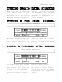
Most radio data modes employ FSK
modulation (Frequency Shift Keying). In this modulation type
two frequencies called MARK and
Shift 850 Hz
0 Hz
AF
SPACE are keyed. The two tones
should be symmetrically tuned
relative to centre of the tuning
indicator.
Tuning with DSP demodulator,
Shift 115-170-115 Hz, Center frequency 1700 Hz
-240 Hz
DSP
Intern
240 Hz
1700 Hz
Trans.Frq.
In Twinplex mode four frequencies are keyed to increase the
data transfer rate. These frequencies may be asymmetrically
grouped (e.g. 115-170-515 Hz).
In the Twinplex menu an option
gives the operator a choice of
six pre-selected shifts in the
Shift 400 Hz
0 Hz
AF
menu item "Fixed shifts".
The tuning of twinplex transmissions must always be done in
such a way that the two INNER
frequencies
are
symmetrical
relative to the tuning indicator
centre.
INTRODUCTION - PAGE 16
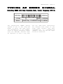
Automatically pre-selection CW-MORSE demodulator
Bandwidth 200 Hz, Center frequency 800 Hz
-400 Hz
400 Hz
CW-Morse
Intern
800 Hz
Trans.Frq.
The transmission of Morse is often done by simply keying the
carrier on and off. This modulation is output by the receiver
as a tone.
With no signal (tone) present
the bargraph will remain turned
off, whereas when a signal is
present one bargraph element
will turn on at a position determined by the value of the
beat frequency relative to the
selected centre frequency.
The bandwidth of the CW demodulator may be adjusted between 50
BW: 800 Hz
0 Hz
AF
and 1200 Hz. As a standard adjustment a bandwidth of approximately 600-800 Hz is recommended. In case of unstable
transmission the bandwidth must
be increased up to 1000 Hz. The
narrower the bandwidth, the better the SNR of the demodulator.
The automatically adjusted FIR
filter provides an optimized
SNR.
In addition to the bandwidth the
centre frequency may be changed
from 600 Hz to 1800 Hz, the centre frequencies 800 Hz and 1000
Hz being standard.
Tuning a DSP demodulator,
Shift 800 Hz, Centre frequency 1900 Hz
-480 Hz
DSP
Intern
480 Hz
1900 Hz
Trans.Frq.
Weather and press facsimile signals transmitted in the HF bands
are frequency modulated. Satellite transmissions from e.g Meteosat are amplitude modulated.
In all modes the tuning of the
FM or generated AM signal is
done symmetrically around the
Shift 800 Hz
0 Hz
AF
centre of the bargraph. Weather
chart signals containing no grey
levels
are
characterized
by
white level information being
dominant, and as a result of
this one or two elements of the
left side of the bargraph will
be more intensively lit.
INTRODUCTION - PAGE 17
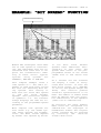
Selecting "Signal Analysis" with pre-selection "Narrow Shift"
High Precision Mode, Center frequency 1700 Hz
MFSK signals like PICCOLO or COQUELET employ from six to thirteen tones. Therefore tuning is
most
easily
done
using
the
"Signal Analysis" software. The
downmost field displays graphically the various tones which
have been sampled over a certain
time interval. In this case the
signal shown is a PICCOLO-MK6
transmission. By tuning the re-
ceiver or changing the WAVECOM
center frequency in the menu
field "Center Frq." the tones
must be symmetrically grouped
around the center "0".
Minor frequency deviations up to
5 Hz are automatically compensated for modes utilizing the
AFC (Automatic Frequency Control) function.
Selecting "Signal Analysis" with DSP-MODE
Pre-selection "Normal Shift", Center frequency: 1140 Hz
INTRODUCTION - PAGE 18
-6000Hz
6000Hz
FFSK
Intern
Schift: 10000Hz
Trans.Frq. 21400000 Hz 21.4MHz
The Europe-wide ERMES paging
system is one of the very few
modes in which the IDLE state
(no information) is not symmetrical to centre frequency. There
fore the VHF-UHF receiver must
be adjusted in such a way that
the two IDLE state indications
are shifted four steps to the
night (dark fields). Only when
information
is
transmitted
(TRAFFIC stak) may the two light
fields be observed.
INTRODUCTION - PAGE 19
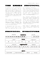
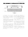
A basic understanding of how
digital information is transferred by land line or radio
links is necessary to fully exploit the many features of the
W4100DSP. It is assumed that the
user is familiar with the general working of telecommunication systems, in particular radio systems.
represented by an infinite continuum of states. For example
live music is analogue information, whereas the same music recorded on a CD has been transformed into digital information
imprinted in the surface of the
disc. Digital information or
data is not only text, it is
also speech, music or images.
By digital information we mean
information which is represented
by discrete states of the transmission medium. In contrast to
this analogue information is
A land line, shortwave link,
satellite link or any other way
of connecting two points for
communications is called a channel.
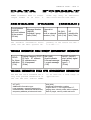
The basic building block of data
and telegraph signalling is the
"bit",
a
word
derived
from
"binary digit", so called because it can assume only one of
two states, " Current" (logical
'1', "Mark" or low frequency,
positive voltage) or "No Current" (logical '0', "Space" or
high frequency, negative or zero
voltage).
made
between
source
coding,
which is the coding used to communicate between a data source
or sink (a teleprinter, a PC)
and data communication equipment, e.g. a modem or a decoder,
and channel coding, which is the
coding used on the channel between the transmitting and receiving
data
communication
equipment. Sometimes the source
code is also used as the channel
code.
On the channel one or more bits
may be represented by a signalling unit called a Baud (Bd).
Bits are assembled into patterns
or codewords with a certain
length which is expressed in
number of bits. The codewords
represent all or a part of the
entire alphabet including letters, numbers, special characters and control codes, or represent the pixels of a fax or
the digitised speech.
Codewords are assembled into alphabets or codes. In some codes
the codewords are of unequal
length. A distinction should be
The Morse code is an unequallength code. Codewords are composed of dots - the smallest
unit -, dashes and spaces, one
dash being equal to three dots.
"E" is the shortest word represented by a dot equal to one '1'
and 0 (zero) is the longest
codeword represented by dashdash-dash-dash-dash" equal to 19
dots, '1110111011101110111' in
binary notation. The reason for
the unequal length of the codewords is to reduce the amount of
work
for
the
operator
when
transmitting many messages. Samuel Morse found by visiting a
INTRODUCTION - PAGE 20
Philadelphia
printing
office,
that the compositors had sorted
the lead types in such a way
that the types most frequently
used were the ones most easily
accessible.
An example of an equal-length,
but non-integral code is the
Baudot or ITA-2 alphabet, which
was formerly in use on the majority of the world's land lines
and radio links. It is still the
base for many codes constructed
later, as compatibility to existing equipment and networks is
essential.
In the ITA-2 code a character is
represented by five bits. For
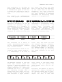
To enable the receiving end of a
data or telegraph link to interpret the received codewords in a
meaningful way, the receiver
must first be synchronized to
the incoming bitstream, and next
achieve codeword phase. Basically the receiver will search
for a certain bit pattern in the
bitstream and when found transmitter and receiver are synchronized.
Before the widespread use of
electronic circuits all telegraph devices were of electromechanical nature and therefore
prone to mechanical wear and
tear. This in turn necessitated
comparatively large tolerances
and made stable synchronization
over even short periods difficult. To overcome this serious
problem,
the
ITA-2
alphabet
adopted what is known as startstop or asynchronous operation,
which achieves synchronism for
each codeword.
In start-stop systems a codeword
is wrapped into an "envelope"
instance the letter "D" is represented
by
the
codeword
'10110'. As we have five bits
which can assume one of two possible states we are able to represent 25 = 32 characters. However the number of all letters,
figures, and special characters
add up to more than 32. Therefore a trick is employed: ITA-2
makes distinction between two
cases, lower (letters) case and
upper (figures) case. Shifting
between these cases is accomplished by special shift characters. In this manner it is possible to transfer (2 x 32) - 6 =
58 characters (the last six are
subtracted because they have
same functions in either case).
consisting of a leading start
bit (logical '0') and one or
more trailing stop bits (logical
'1') - for ITA-2 the codewords
are 1 + 5 + 1.5 = 7.5 bits long.
Bit
synchronization
is
then
achieved by detection of the
start element. The stop element
(s) serve the purpose of telling
the receiver to reset its detection mechanisms and wait for the
next start bit. To ensure proper
operation of the mechanical devices the stop bit was extended
to have 1.5 times the length of
a data bit, which accounts for
the term "non-integral" earlier
in this section.
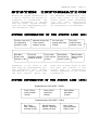
In synchronous systems there is
continuous synchronization between the sending and receiving
devices either by special nonprinting control characters being inserted into the messages
at regular intervals or the
codewords themselves being constructed to facilitate synchronism. To maintain synchronism
special idle or sync characters
are transmitted when no traffic
INTRODUCTION - PAGE 21
is transmitted. In contrast to
start-stop systems only elements
having a duration of an integral
multiple of the duration of the
minimum signal element are used
- isochronous sequence.
For burst mode or packet like
transmissions a leading preamble
of either a sequence of alternating zeros and ones and/or a
repeated fixed pattern is often
used for synchronization purposes.
The bitrate is the number of
bits transmitted per second,
measured in bps.
If four levels were used below,
the baudrate would still be 100
Bd, but now the bitrate would be
doubled to 200 bps, each baud
representing two bits.
The telegraph speed or baudrate
is the inverse of the duration
of one channel signalling unit
and has the unit Baud (Bd). So
if one channel signalling unit
has a duration of 10 ms, then
the telegraph speed is equal to
1/0,001 = 100 Bd. If the channel
has only two signalling levels,
e.g. 0V and +5V, bitrate is
equal to baudrate, i.e 100 bps.
By signalling levels is meant
the different values a signalling unit may assume - for binary signalling it is two levels, but many systems utilize
more than two levels. For radio
transmission the levels may be
represented by frequency, phase
or amplitude levels.
In principle to transmit telegraph information on a radio
path you only need a transmitter
which is keyed on and off. However due to the high level of
disturbances
frequency
shift
keying (FSK) is used. In this
mode the transmitter is continously on, but transmits alter-
nately on two different frequencies, one representing "Mark"
level and the other "Space"
level. The difference between
the two frequencies (frequency
deviation) is called the "Shift"
and may for instance be 170, 425
or 850 Hz.
Traffic between users may be
handled in a number of ways depending
on
requirements
and
equipment available.
If information is sent in both
directions, but one in direction
at a time it is referred to as
simplex.
If information is sent only in
one direction it is referred to
as one-way traffic.
If information is sent in both
directions simultaneously it is
referred to as duplex.
INTRODUCTION - PAGE 22
Ongoing efforts are being made
to exploit as much as possible
of a given channel capacity. One
way is to process data to be
transmitted in such a way that
redundant information is removed
before
transmission.
Another
method is to transmit more than
one channel on a radio link.
This may be achieved either in
the frequency or time domain or
a combination hereof.
The removal of redundant information is called compression.
The ratio between the size of
the original data and the compressed data depends on the nature of the data and the efficiency of the compression technique. These techniques are used
in commonly known compression
software like PKZIP, ARJ and
LHARC. Compression is used in
the PACTOR mode.
In frequency multiplex (FDM) a
carrier frequency is modulated
with a number of sub carriers
within
a
standard
telephony
channel from 0.3 kHz to 3 kHz.
Each sub carrier carries a data
signal. The sub carriers may be
amplitude, frequency or phase
modulated. The more common is
narrow shift frequency modula-
tion. Each channel is independent of the other ones and may
transmit with a different speed
or use a different alphabet or
system.
In time multiplex (TDM) each
data source is allowed access to
the aggregate channel (line or
radio link) in well-defined time
slots. To keep pace with the incoming bitstream, the aggregate
channel speed must be the sum of
the speed of the individual
channels. All channels must have
identical
speeds.
However
a
channel subdivision scheme has
been standardized so that up to
four sub channels may share one
channel.
The overwhelming majority of radio data systems will transmit
the individual bits of a codeword one after the other in serial transmission. But real-time
or high volume data systems like
digitised secure voice, computer
network access and image or file
transfer often uses parallel
transmission. The serial codewords are fed to a serial-toparallel converter and then to
the sub carrier modulators of a
FDM.
INTRODUCTION - PAGE 23
To protect data transmissions
against
interception
various
methods are in use.
Encryption may be on-line or
off-line.
On-line
encryption
takes places at transmission
time, whereas off-line encryption is done before transmission, usually in the form of
coding the clear language message into five letter or five
figures groups. This is done by
a key sequence.
Bit inversion inverts logical
zeroes of a codeword with logical ones and vice versa either
in a static pattern, e.g. bit 3
and bit 5 or in a dynamic pat-
Due to the unstable nature of
the radio media especially in
case of HF links a number of
techniques have been devised to
protect data and ensure a high
degree of error free transmission. This is especially important for the transmission of encrypted information.
To protect the data extra - redundant - information must be
added to the data to be protected. Either bits are added to
existing source code or the
source alphabet is converted
into a completely new alphabet
before channel transmission. In
addition certain procedures protocols - are used for the exchange of information.
Depending on the nature of the
radio link - one-way, simplex or
duplex - channel codes and protocols have been devised to detect or correct transmission errors or to both detect and cor-
tern depending on the value of
the codeword.
Bit transposition replaces bits
in one position in a codeword
with bits in another position.
Shift-register encryption uses
one or more shift-registers into
which the clear language message
is shifted and extorted with a
key or part of itself. Taps in
various positions of the registers may feed bits back to the
input to complicate decryption
by
interceptors.
The
shiftregisters of the transmitting
and receiving equipment must be
initialised to the same value the seed.
rect errors.
ARQ is a technique in which the
Information
Sending
Station
(ISS) transmits information in
such a way that the Information
Receiving Station (IRS) is able
to detect a transmission error
and then ask for repetition of
the character or block of characters in error. This technique
is used in simplex and duplex
channels.
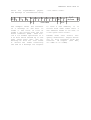
One code in international use
for ARQ is the balanced ITA-3
code consisting of seven bits
with a constant mark-space ratio
of 3:4. A ratio different from
3:4 in a received codeword will
be an error and a RQ (Request
for Repetition) is released.
This code has no correcting capability.
Another ARQ code is the ARQ-1A
parity code. The codewords of
this code also consist of seven
INTRODUCTION - PAGE 24
bits, 6 data and 1 parity bit.
The parity bit is set to 1 or 0
depending on the number of logical '1's in the six data bits of
the codeword.
The Bulgarian ASCII system uses
yet
another
form
of
parity
check. A checksum is calculated
for a data block and appended to
the transmitted block. The IRS
calculates the checksum once
again and compares the result
with the checksum received. If
the checksums are not equal a RQ
is issued. The checksum calculation is often done using a
method called a Cyclic Redundancy Check (CRC).
In one-way systems there is of
course no return channel so the
IRS cannot request repetitions.
Therefore the codes used must
very robust and be able to correct errors at the receiving end
- Forward Error Correction (FEC)
is used.
One of the worst enemies of oneway links is burst noise which
may damage many succeeding bits.
To combat this type of noise bit
spreading or bit interleaving is
used. The bits of succeeding
codewords are spread in time. In
this way burst errors will only
influence a few bits of each
codeword and the error correcting code may have a decent
chance to correct the errors.
The HNG-FEC and RUM-FEC channel
codes use this method.
Another method is codeword repetition in which a codeword is
repeated
several
characters
later in the transmission. To
improve error detection and correction the repeated character
may be bit inverted. The original character and the repeated
character are then compared at
the IRS. SI-FEC and SITOR-B are
examples of this type of code.
One code type has been successful in particular. That is the
convolution code in which the
value of the parity bits depends
of the values of a number of
preceding data bits. The data
bits
are
shifted
through
a
shift-register with taps. The
output at the taps are extorted
to form the value of the parity
bits. After convolution the bits
are interleaved to further improve noise immunity. FEC-A is
such a code.
INTRODUCTION - PAGE 25
DUPLEX
Analysis
ARQ-E
ARQ-E3
ARQ-N
ARQ-M2-342
ARQ-M2-242
ARQ-M4-342
ARQ-M4-242
DUP-ARQ
DUP-ARQ-2
POL-ARQ
BULG-ASCII
Full duplex mode is used when
in case of point-to-point connections there is a need for
simultaneous two-way communication. In case of voice communication duplex permits simultaneous and independent directions of speech like an ordinary telephone connection. Full
duplex data communications is
used when there is a need for a
very high data throughput in
both directions (e.g. on the
main radio links of diplomatic
networks) and where terminal
equipment, which uses special
protocols operating in full duplex, is employed.
Full duplex connections need
separate receiving and transmitting antennas at each station. As reception and transmission are simultaneous an efficient antenna decoupling is
necessary.
Full duplex equipment transmits
an acknowledgement on frequency
f2 for data blocks received on
f1. Should any one of the two
frequencies be subject to disturbances, the transfer of data
in either direction becomes impossible.
By employing ARQ-data protection equipment and the corresponding coding it is possible
even on poor short wave links
to obtain levels of errors so
low that the link quality is
comparable to that of a telephone line and therefore permits an unlimited data transfer.
Modern ARQ equipment is not
only capable of teletype transmission, but computer data, fax
data, etc. may also be transferred.
Frequency f1
Transmitter
Receiver
Frequency f2
Data Terminal
Duplex ARQ
Equipment
Duplex ARQ
Equipment
Receiver
Transmitter
Data Terminal
INTRODUCTION - PAGE 26
SIMPLEX
Analysis
SITOR-ARQ
TWINPLEX
SI-ARQ
SWED-ARQ
ARQ6-90
ARQ6-98
HC-ARQ
PACTOR
A LI S
SI-AUTO
G-TOR
The simplex mode is based on
the rapid switching of receiving and transmitting directions
during the data transfer. In
this way a two-way link is established
between
two
radio
stations, but only in one direction at a time. While it is
possible in principle to employ
FEC, ARQ is mainly employed.
When employing ARQ a data block
of distinctive length (e.g. 30
bits) and with additional control information is transmitted. This permits the receiving
station to perform an error
check.
After transmitting a data block
the direction of transmission
is changed. The receiving station informs the transmitting
station whether the received
data block must be repeated.
Then the direction of transmis-
sion is changed again. The
transmitting station transmits
the next data block if the preceding block was acknowledged
or repeat it if the acknowledgement was negative or no acknowledgement at all was received. This procedure is repeated approximately once per
second.
By
transferring
the
necessary control sequences a
change of direction is continuously possible.
Based on historic reasons these
type of systems are designated
as simplex systems in spite of
their half duplex characteristics. A decisive factor in the
choice of system is the cost.
Full duplex systems need another antenna with its own mast
displaced from the first one,
another receiver and a remote
control system for the displaced receiver.
Frequency f1
Data Terminal
Simplex ARQ
Equipment
Transceiver
Transceiver
Simplex ARQ
Equipment
Data Terminal
INTRODUCTION - PAGE 27
FEC
Analysis
FEC-A
SITOR-FEC
SI-FEC
AUTOSPEC
SPREAD-11
SPREAD-21
SPREAD-51
HNG-FEC
RUM-FEC
DUP-FEC-2
FEC modes (Forward Error Correction) base on a one-way data
transfer from one transmitting
station to one or more receiving stations. It is also used
in cases where the receiving
station may not transmit (radio
silence). Earlier systems used
unprotected 50 Baud transmission, but in modern systems today efficient error correcting
devices are utilized. The employment of error correcting
codes means a marked increase
in transfer quality.
A simple way of error correction is to transmit the same
data on several channels but
delayed in relation to each
other. A more efficient error
correction is obtained by using
a convolution code. This coding
method employs shift registers
and modulo two addition. The
Data Terminal
FEC Coder
Transmitter
multiplexing circuit transmits
information and parity bits alternately. The number of control bits is equal to the number of information bits.
Another method of FEC is block
coding. A parity block is added
to a data block of a randomly
chosen length. The parity block
is constructed by the binary
division of the bits of the
data block by a generator or
parity polynomial. Inside the
transmitter this division results in a parity block, that
then is transferred to the data
block.
The data transfer quality may
also be improved noticeably with a very reasonable effort by utilizing interleaving techniques.
Receiver
FEC Decoder
Data Terminal
Printer
Receiver
FEC Decoder
Data Terminal
Printer
Receiver
FEC Decoder
Data Terminal
Printer
INTRODUCTION - PAGE 28
MFSK
Analysis
Piccolo-MK6
Piccolo-MK12
Coquelet-13
Coquelet-80
ALIS-2
Multi Frequency Shift Keying
(MFSK) systems are quite often
heard on short-wave. Systems
transmitting one tone at a time
or several tones at the same
time may be encountered. Even
fast simplex systems use MFSK
with a tone duration of only 4
ms.
MFSK systems deviate from the
classical binary transmission
of '0' (Mark) and '1' (Space),
because in MFSK each tone has a
higher
information
density.
This is the reason for a very
high increase in the element
period in MFSK compared with
binary transmissions having the
same baud rate. This produces a
substantial increase in the insensivity to multipath propagation and noise.
Early Piccolo versions (Mark 1,
2 and 3) employed 32 tones.
Each tone represented a character of the ITA-2 telegraph alphabet. Later it was found that
two sequential tones improved
the SNR. The more recent Piccolo Mk 6 uses two times six
possible tones each having a
duration of 50 ms. This results
in 36 possible combinations of
Coquelet-8
which 32 are necessary for the
transfer of ITA-2 characters.
Piccolo Mk12 uses 12 tones so
that the transfer of ASCII
characters is possible.
The Coquelet-8 and Coquelet-13
modes employ the same principle
of transmission. Coquelet-8 has
additional tone combinations,
which are used for improving
transmission reliability. Coquelet-13 is an asynchronous
system.
MFSK modes have small spacing
between adjacent tones. Though
the distance between adjacent
tones in the early 32 tone Piccolo versions was only 10 Hz,
the recent versions use 20 Hz
spacing. For Piccolo Mk6 this
means a total necessary bandwidth of 180 Hz, and for Piccolo Mk12 300 Hz. The
tone
spacing necessary to avoid inter symbol interference is calculated as the inverse of the
tone duration.
MFSK
systems
as
COQUELET-80
also employ forward error correction or are full duplex-ARQ
or simplex systems as ALIS-II
8FSK.
INTRODUCTION - PAGE 29
VHF-UHFDIRECT
Analysis
POCSAG
ERMES
PACKET-9600
Contrary to what is the case on
short-wave many different types
of transmission may be encountered in the VHF-UHF bands.
Pure data transmission systems,
as known from the HF bands, are
quite
rare
with
satellite
transmissions as an exception.
Compared to the baudrates used
on the HF bands the rates on
the VHF-UHF bands are high.
POCSAG employs 512, 1200 and
2400 Baud, adaptive GOLAY 300
or 600 Baud ERMES 3125 Baud and
INFOCALL, FMS-BOS, ATIS, MPT1327/1343 and ZVEI-VDEW 1200
Baud. New commercial modes employ speeds up to 9600 Baud,
while radio amateurs with special transmission and reception
equipment
already
work
with
9600 Baud GFSK.
The modulation methods used on
HF: 2FSK, 4FSK and GFSK are
also used on VHF-UHF. FFSK is a
special implementation of the
FSK modulation; the frequency
shift is achieved with welldefined phase states. Modern
systems like ERMES and MODACOM
use an extended 4-PAM/FM modulation (Gaussian) scheme. At
present phase modulation is an
exception in the VHF-UHF bands.
GOLAY
INFOCALL
POCSAG, INFOCALL and GOLAY are
pure FEC systems with extensive
error detection and correction
capabilities. The digital signal systems FMS-BOS and ATIS
are ARQ simplex systems. If a
call has not been acknowledged
within a certain time the call
is repeated.
A detailed description of the
various systems may be found in
the "MODES" section of this
manual.
A characteristic of the VHF/UHF
transmission modes is the way
in which the carrier is modulated. Some like POCSAG, ERMES
mode or PACKET-9600 use DIRECT
(carrier) modulation. The modes
may only be decoded using the
receiver IF signal output.
Other
systems
like
MPT1327/
1343,
PACKET-1200
and
ACARS
utilize
INDIRECT
modulation.
Here the carrier is modulated
with another carrier. To demodulate INDIRECT modes the receiver demodulator is necessary
and the signal can thus only be
taken from the receiver AF output. A detailed description of
the carrier modulation methods
may be found on the end of this
chapter.
INTRODUCTION - PAGE 30
VHF-UHFINDIR
Analysis
SELCALanalog
PACKET-1200
MPT-1327
ACARS
ATIS
FMS-BOS
ZVEI-VDEW
GMDSS/DSC-VHF
Contrary to what is the case on
short-wave many different types
of
t ran sm iss i ons
may
be
encountered
in
the
VHF-UHF
bands. Pure data transmission
systems, as known from the HF
bands, are quite rare with
satellite transmissions as an
exception.
Compared to the baudrates used
on the HF bands the rates on
the VHF-UHF bands are high.
Most
indirect
modes
uses
1200bps, and ACARS 2400 bps.
The
most
common
modulation
methods used on VHF/UHF are
2FSK, FFSK, 4FSK and GFSK. FFSK
is a special implementation of
the
commonly
used
FSK
modulation; the frequency shift
is achieved with well-defined
phase states. Modern systems
like ERMES and MODACOM use an
extended
4-PAM/FM
modulation
(Gaussian) scheme. At present
phase
modulation
is
an
exception in the VHF-UHF bands.
The digital signaling systems
FMS-BOS, MPT-1327, ACARS and
ATIS are simplex ARQ systems.
If
a
call
has
not
been
acknowledges
within
a
predetermined time window, the
call is repeated.
PACKET-1200 is originally based
on the X.25 protocol. In this
mode
the
data
blocks
are
repeated
until
the
reciever
acknowledges
error
free
reception.
The
analog
selective
call
systems ATIS and GMDSS/DSC are
one-way
systems
without
an
acknowledgement, if this is not
explicitly requested. A more
detailed
description
of
the
various systems may be found in
the "MODES" section of this
manual.
All indirect modes - subcarrier
modulation
are
compatible
with
commonly
found
voice
equipment.
The
digital
information is carried over the
voice channel as FSK. Thus the
device may used for voice and
data transmission. An exception
is ACARS because air radio per
tradition utilizes AM.
Decoding
indirect
modes
can
only
take
place
using
the
rece ive r
NF
out put .
Th e
receiver serves as demodulator
of the FM or AM carrier, while
the
W4100DSP
demodulator
processes
the
subcarrier
modulation.
A more detailed description of
the carrier modulation methods
may be found at the end of this
chapter.
INTRODUCTION - PAGE 31
FAX-SSTV-HELL
Analysis
WEATHER-FAX
PRESS-FAX
SSTV
FELDHELL
Weather charts to be transmitted
are fastened to a revolving drum
and
illuminated
by
a
light
source. The drum is then scanned
by a light sensor moving along
the axis of the drum. The voltage output from this sensor is
converted into tone frequencies
modulating the transmitter.
The number of revolutions per
minute (RPM) is a measure of the
speed of the drum on the transmitting side. The index of cooperation (IOC) is a measure of
the speed with which the sensor
moves along the axis of the
drum.
A fax transmission begins with a
tone of 300 or 675 Hz. It has a
duration of 5-10 seconds and is
very well suited for exact tuning purposes. This tone conveys
the IOC value. Then 30 seconds
of alternations
between the
frequencies representing black
and white levels are transmitted, the switching frequency being 1-4 Hz. These carry the RPM
information and the receiver is
now synchronized so that the
picture will start in the right
position.
Subsequently the transmission of
the picture begins properly. The
output to the video monitor has
a resolution of 640 x 480 pixels
and 16 grey levels. Output to a
graphics printer is done via the
Centronics parallel interface.
Weather-FAX pictures are continuously
printed,
so
the
printer should at least be able
to print 150 characters/min.
At the end of transmission the
stop signal is sent. This consists of a switch-off signal of
450 Hz having a duration of 5
seconds followed by 10 seconds
of the frequency representing
black level.
5 % white
95 % black
f white
f black
PAUSE
IOC-TONE
5-10 seconds
SYNCHRONISATION
10 - 30 seconds
DATA
10 -40 minutes
BREAK SIGNAL
5-20 seconds
PAUSE
INTRODUCTION - PAGE 32
The HF and VHF/UHF modes decoded
by the W 4100DSP use different
carrier modulation methods.
The most frequently used modulation techniques are 2FSK using
two tone frequencies, MFSK with
four or more tones and phase
modulation methods 2PSK, 4PSK
and 8PSK. The DSP demodulator
handles
the
demodulation
these modulation methods.
of
The HF-transmission, INDIRECT FM
modulation, INDIRECT AM modulation and DIRECT FM modulation
modes must be distinguished. Depending on the mode AF and HF
inputs (HF modes) may be used,
or only AF or IF inputs.
Most modes in HF bands use SSB
modulation with suppressed carrier and AF subcarrier frequency
shift to emulate the direct keying of the carrier frequency in
previous use. Decoding can be
done from the AF- or IF output
(USB, LSB, CW or FAX demodulator).
PAGER modes and PACKET-9600 Bit/
s
on
VHF/UHF
use
DIRECT
(carrier) FM modulation. The
shift may be 3000 Hz to 9000 Hz.
Decoding is only possible from
the receiver IF output.
The latest generation of receivers (e.g. ICOM and AOR) provides
a direct discriminator output
for decoding these modes.
Modes using INDIRECT modulation
(subcarrier modulation) are double modulated. One method is to
modulate a frequency modulated
carrier
with
FSK
(Frequency
shift keying). For decoding, the
receiver FM demodulator output
is required. Examples of INDIRECT modulation are PACKET-1200,
ATIS, analog and digital tone
call systems. Decoding is only
possible from the receiver AF
output.
Another method of INDIRECT modulation (subcarrier modulation)
uses
AM
carrier
modulation,
which in turn is FSK modulated.
For decoding the receiver AM de-
modulator output is required.
ACARS is an example of this
method. Decoding is only possible from the receiver AF output.
INTRODUCTION - PAGE 33
ACARS
ALIS
ALIS-2
ARQ-E
ARQ-E3
ARQ-N
ARQ-M2-242
ARQ-M2-342
ARQ-M4-242
ARQ-M4-342
ARQ6-90
ARQ6-98
ASCII
ATIS
AUTOSPEC
BAUDOT
BULG-ASCII
CCIR
CCITT
CIS-11
CIS-14
CIS-36
COQUELET-8
COQUELET-13
COQUELET-80
CW-MORSE
DGPS
DUP-ARQ
DUP-ARQ-2
DUP-FEC-2
DTMF
EEA
EIA
ERMES
EURO
FEC-A
FMS-BOS
GOLAY
G-TOR
HC-ARQ
HNG-FEC
ICAO SELCALL
INFOCALL
METEOSAT
MPT1327/1343
NATEL
NOAA-GEOSAT
PACTOR
PACKET-300
PACKET-1200
PACKET-9600
PICCOLO-MK6
PICCOLO-MK12
POCSAG
POL-ARQ
PRESS-FAX
2400
228.6
240.82
48,64,72,75,86,96,192,288
48,50,96,100,192
96
96
96,200
192
192
200
200
110, 150, 300
1200
68.5
45,50,75,100,180
110, 150, 180, 200, 300
100 ms
100 ms
100
96
10, 20, 40
75 ms, 37.50 ms
75 ms
37.50 ms, 75 ms
20 - 400 BPM
100, 200
125
250
125, 250
70 ms
40 ms
33 ms
3125 Baud
100 ms
96, 144, 192, 288
1200
300/600
100/200/300 adaptive
240
100.05
1000 ms
1200
240 RPM, IOC288
1200
70 ms
Drum Speed 120 RPM, IOC576
100/200 adaptive
300
1200
2400, 4800, 9600
50 ms, 25 ms
50 ms, 25 ms
512, 1200
100, 200
120 RPM
INDIRECT AM
SSB
SSB
SSB
SSB
SSB
SSB
SSB
SSB
SSB
SSB
SSB
SSB
INDIRECT FM
SSB
SSB
SSB
INDIRECT FM
INDIRECT FM
SSB
SSB
SSB
SSB
SSB
SSB
SSB or CW
SSB
SSB
SSB
SSB
INDIRECT FM
INDIRECT FM
INDIRECT FM
4-PAM/FM
INDIRECT AM
SSB
INDIRECT FM
DIRECT FM
SSB
SSB
SSB
SSB
DIRECT FM
INDIRECT AM
INDIRECT FM
INDIRECT FM
INDIRECT AM
SSB
SSB
INDIRECT FM
DIRECT FM
SSB
SSB
DIRECT FM
SSB
SSB
INTRODUCTION - PAGE 34
RUM-FEC
SI-AUTO
SI-ARQ
SI-FEC
SITOR-AUTO
SITOR-ARQ
SITOR-FEC
SPREAD-11
SPREAD-21
SPREAD-51
SSTV
SWED-ARQ
TWINPLEX
VDEW
WEATHER-FAX
ZVEI-VDEW
ZVEI-1
ZVEI-2
164.5, 218.3
96, 200
96, 200
96, 200
100
100
100
102.6
102.6, 68.5
102.6
8, 16, 32 s
100
100
100 ms
60, 90, 120 RPM
1200
70 ms
70 ms
SSB
SSB
SSB
SSB
SSB
SSB
SSB
SSB
SSB
SSB
SSB
SSB
SSB
INDIRECT
SSB
INDIRECT
INDIRECT
INDIRECT
FM
FM
FM
FM
A double click on the lower,
left hand trackball button results in the display of a full
screen menu. This action immediately terminates all operating
modes and input functions which
might have been active. By moving the trackball any desired
function may then be selected.
By clicking the left hand button
the
selected
mode
is
then
started in AUTO mode.
By
clicking
the
right
hand
trackball
button
the
entire
screen is cleared and the main
menu is displayed.
OPERATING MODES - PAGE 2
The main menu incorporates all
sub menus relating to operating
modes as well as analysis and
set-up functions. Menu interaction takes place by turning or
"moving"
the
trackball
and
clicking on the desired function.
The WAVECOM software is based on
a multitasking kernel and can
handle more than one task concurrently. The control of and
interaction with the menu system
occurs without any interruption
of an active function. This allows for example the shift and
centre frequency to be set in
the "Demodulator" submenu without interference to or disruption of the currently active operating mode.
The descriptions of the operating modes which follow, are arranged in alphabetical order.
Future extensions and updates
can thus be incorporated more
easily.
OPERATING MODES - PAGE 3
Frequency range
Frequency Europe
USA
Japan
Center frequency
Shift
Baudrate
Systems
Modulation
Receiver setting
Signal source
VHF/UHF Modes
131.725, 131.525, 131.825 MHz
131.550, 130.025, 129.125, 131.475 MHz
131.450 MHz
1800 Hz
1200 Hz
2400 Bit/s
Packet oriented ARQ (CSMA/CD)
INDIRECT-AM
AM 12.0 KHz, narrow
AF (only)
Aircraft Communications Addressing and Reporting System (ACARS)
is a carrier sensing, multiple
access packet radio system for
aircraft communications. ACARS
operates in the VHF band, mainly
around 130 MHz, using 2400 bps
NRZI coded coherent audio frequency MSK (Minimum Shift Keying
- a particular form of FSK) on
AM to make use of standard aircraft AM communications equipment.
To
receive
ACARS
an
Pre code
Bit synch
Characters synch
Start of Heading
Mode
Address
Technical Acknowledgement
Label
Block Identifier
Start of Text
Text
Suffix
Block Check Sequence
BCS Suffix
directional 108-136 MHz antenna,
a VHF AM receiver
(scanner)
with 13 kHz channel bandwidth
and a corresponding AF output is
necessary. As the ACARS packets
are very short turn the squelch
of the receiver OFF.
To start monitoring ACARS, select “2400.00 Baud“. As only one
speed is used presently, the
ACARS menu does not offer the
option of manually selecting a
speed.
omni-
16 characters, binary '1'
2 characters „+„ , „*„
2 characters SYN, SYN (16h)
1 character SOH (01h)
1 character
7 characters
1 character
2 characters
1 character
1 character
STX (02h) - when no text ETX (03h)
220 characters maximum
Only printable characters
1 character
If single or terminal block ETX,
otherwise ETB (17h)
16 bits CRC sum
1 character, DEL (7fh)
OPERATING MODES - PAGE 4
Messages may be single or multi
block. The pre-key sequence and
the BCS have no parity bits.
ACARS communications are divided
in Category A and Category B.
Using Category A an aircraft may
broadcast its messages to all
ground stations. This is denoted
by an ASCII “2“ in the Mode
field of the downlink message.
The WAVECOM software translates
this character to "A".
Using Category B an aircraft
transmits its message to a single ground station. This is denoted by an ASCII character in
the range “@“ to “]“ in the Mode
field of the downlink message.
The ground station may use either “2“ or the range “‘“ to “}“
in the mode field. All ground
stations support Category A, but
may uplink “‘“ to “}“ in the
Mode field.
number of times until a positive
acknowledgement is received and
the message can be deleted from
storage
or
the
aircrew
be
alerted to its non-transmission.
If an uplink message is found in
error the airborne equipment
will generate a negative acknowledgement (NAK) which triggers an uplink retransmission.
Retransmission is also triggered
by timeout.
Positive
acknowledgement
from
the aircraft consists of the
transmission of the Uplink Block
Identifier of the correctly received block. Positive acknowledgement from the ground station
consists of a similar transmission of the Downlink Block Identifier.
Acknowledgements are placed in
the
Technical
Acknowledgement
field.
The WAVECOM software translates
the ground station address (also
called the Logical Channel Number) to a number in the range
0..29.
The general response message label is “_DEL“ (5fh 7fh). Messages with this label contain no
information except acknowledgements and are used for link
maintenance.
A station will transmit after
having monitored the HF channel
for traffic, otherwise it waits
until the channel is clear. If a
collision occurs between the
packets of two stations transmitting at the same time, they
will back-off and new transmission intervals will be set by
random interval timers in the
radio equipment.
The traffic exchanged can be requests for voice communication,
weather reports, access to airline computer systems, reading
of aircraft automatic sensors,
flight plans, messages to be
routed to destinations in the
international airline data network - in fact much traffic previously carried by voice, has
been transferred to ACARS.
At the receiving end a block
check calculation is made and
compared to the calculation appended to the packet by the
transmitting station. If the
downlink messages contains errors no response will be given
and the transmitting station
will retransmit the packet a
The text field of the ACARS
packet is used for messages with
a fixed format, free text or a
mixture of formatted and free
text. Standard 7 bit ASCII is
used, bit 8 is an odd parity bit
and LSB (bit 1) is transmitted
first.
OPERATING MODES - PAGE 5
(#8) 06-11-1996 18:43:32 M=06 ADDR= HB-INR TA=Q ML=Q0 B=6
MSN=0635 FID=SR6767
(Bold typeface indicates W4100DSP generated characters)
(#8)
W41PC generated message number
06-11-1996 18:43:32
W4100DSP generated timestamp (optional)
M=
Mode Category A = A,
Category B = 0..29
ADDR=
Aircraft address
(aircraft registration or flight identifier)
TA=
Technical acknowledgement
(downlink 0..9, uplink A..Z, a..z, NUL (00h)
ML=
Message Label (message type)
B=
Uplink/Downlink Block Identifier
(downlink 0..9, uplink A..Z, a..z, NUL (00h)
MSN=
Message Sequence Number
FID=
Flight Identifier
In this case record #8 decoded
at 18:43:32 contains a message
from a Swiss aircraft with registration HB-INR using logical
channel 06 to transmit and acknowledgement of uplink block Q
and a link test (Q0) with block
identifier 6 and message sequence number 0635 (here the
time in minutes and seconds after the hour is used - other
formats are also in use). The
flight is Swissair SR6767.
A few examples of the more important or frequently seen ACARS
messages:
M=06 ADDR= HB-IND TA=NAK ML=_ B=3 MSN=2810 FID=OS005
Using logical channel 06, an unsolicited (TA=NAK) general response _ without information
is transmitted as block 3 from
aircraft HB-IND on flight OS005
M=06
with sequence number 2810. General responses are mainly used
for block acknowledgement purposes.
ADDR= TA=NAK ML=SQ B= 00XSZRH
This is a “squitter“ - an id and
uplink test message transmitted
at regular intervals from ground
stations. This one is a squitter
(SQ) version 0 (00) from a SITA
(XS) ground station in Zurich,
Switzerland (ZRH). The ¢ denotes
the ASCII NUL character (00h)
used for broadcasts. A block
identifier is not used.
M=06 ADDR= OY-MDS TA=5 ML=:; B=131125
This is a data transceiver auto
tune message (:;) from ground
station 06 commanding the ACARS
transceiver of aircraft OY-MDS
to change its frequency to
131.125 MHz. At the same time
acknowledgement is given for
the aircraft's downlink block
5.
OPERATING MODES - PAGE 6
Frequency range
System
Baudrate
Modulation
Receiver setting
Signal sources
HF-MODES
SIMPLEX
228.66 Baud
SSB or DIRECT-FSK
CW, LSB or USB
AF or IF
A LI S
Analysis
228.67 Baud
Auto
96.0 Baud Var
Demodulator
Options
Force LTRS-FIGS
ITA-2
ECC ison
ALIS is a simplex system and operates at a speed of 228.66 Baud
on the radio link.
ALIS is described in the report
of the ITU Reports of the CCIR
1990 “Fixed Service at frequencies below about 30 MHz”. The
abbreviation ALIS is derived
from <Automatic Link Set-up>.
The transmission block of the
standard ARQ system consists of
2 identification bits, 30 data
bits and 16 CRC bits. Data
transmission is transparent for
ALIS. Known systems are however
structured
around
six
ITA-2
characters.
The two identification bits indicate one of four possible operating states. The CRC checksum
enables detection and correction
of transmission errors.
The acknowledgement block has a
length of 16 bits. The total
transmit/receive cycle for ALIS
is 111 bits which corresponds to
a duration of 485.4 ms. An error
free transmission is equivalent
to a terminal baud rate of 100
Baud Baudot.
The ALIS system automatically
determines the optimal operating
frequency after having received
a CALL command. The station then
sends a synchronisation word,
address, block counter and a
status word. The receiving station correlates this bit sequence and synchronises itself.
If the data transmission link
fails, ALIS will search for a
new frequency to re-establishing
the link.
OPERATING MODES - PAGE 7
Frequency range
System
Baudrate
Modulation
Receiver settings
Signal sources
HF
SIMPLEX
240.82 Baud
SSB or DIRECT-FSK
CW, LSB or USB
AF, HF or IF
A LI S-2
Analysis
Demodulator
Options
240.80 Baud
96.0 Baud Var
ALIS-2 is a simplex system operating with a baud rate of 240.82
baud.
ALIS-2
is
described
in
the
“Report of the CCIR 1990, Fixed
Service at Frequencies below
about 30 MHz” of the ITU. ALIS-2
is derived from Automatic LinkSetup.
ALIS-2 are 8FSKmodulated. The
tone spacing is 240 Hz, and the
tone duration is 4.15254 ms. The
transmission block consists of
55 tri-bits, resulting in 165
bits per frame. In addition to
the preamble of 21 bits, each
block contains 126 data bits.
The preamble includes an identification code, allowing different systems to be identified.
Two identification bits signal
four operational states: Traffic, idle, RQ and binary data
transfer.
The
16
bit
CRCchecksum serves the detection of
transmission errors
correction purposes.
and
error
The overall transmission and receive cycle of ALIS-2 is 354
bits, which is equivalent to 490
ms. In case of an error free
data transmission the terminal
baudrate is 720 bit/s.
ALIS-2 almost always
ITA-5 ASCII alphabet.
uses
the
The ALIS-2 system automatically
determines the optimum operating
frequency after having received
a CALL command. The station then
sends a synchronization word,
address, block counter and a
status word. The receiving station correlates this bit sequence and synchronizes itself.
If the transmission link is interrupted, ALIS-2 will search
for a new frequency to reestablish the link.
OPERATING MODES - PAGE 8
Frequency range
System
Baudrate
Modulation
Receiver setting
Signal sources
HF-MODES
DUPLEX
46.2 - 288.0 Baud
SSB or DIRECT-FSK
CW, LSB or USB
AF or IF
The duplex ARQ-E systems operate
at speeds of 48,
64.3, 72,
85.7, 96, 192 and 288 Baud on
the radio link.
ARQ-E employs the ARQ-1A alphabet with parity checking which
allows the detection of transmission errors.
Synchronisation for the ARQ-E
operating mode may be started by
the selection of a baud rate. An
“AUTO” program start causes the
automatic determination of the
frequency shift and baud rate to
be executed first. The signal
polarity (USB or LSB sidebands)
is automatically detected.
For short-wave transmissions the
synchronous
full
duplex
ARQ
(Automated Request) modes have
become very significant. The
five inner data steps correspond
to the ITA-2 alphabet.
After synchronisation to an ARQE system has been achieved, the
detected repetition rate is displayed (4 ,5 or 8 cycles). This
parameter gives certain clues as
to identical transmission nets.
If a continuously repeated character (often FFFF) is decoded
whilst working in the ARQ-E
mode, it is most likely an ARQE3 system being monitored.
Full duplex systems transmit the
RQ character after having detected an erroneous character or
in the presence of excessive
signal distortions. The remote
station subsequently repeats the
last three, four or seven characters preceded by the RQ character.
To maintain synchronisation between the two stations both
transmitters
operate
continuously and send the idle bit pattern if no traffic is transmitted.
OPERATING MODES - PAGE 9
Frequency range
System
Baudrate
Modulation
Receiver setting
Signal sources
HF-MODES
DUPLEX
48.0 - 288.0 Baud
SSB or DIRECT-FSK
CW, LSB or USB
AF or IF
Analysis
Auto
Demodulator
Options
48.0 Baud
72.0 Baud
96.0 Baud
100.0 Baud
192.0 Baud
96.0 Baud var
ITA-2
Force LTRS-FIGS
ARQ-E3 systems often operate at
speeds of 48, 50, 96, 192 and
288 Baud on the radio link.
Synchronisation for the ARQ-E3
operating mode may be started
with the selection of a baud
rate. An “AUTO” program start
causes the automatic determination of the frequency shift and
baud rate to be executed first.
The signal polarity (USB or LSB
sidebands) is automatically detected.
After synchronisation to an ARQE3 system has been achieved, the
detected repetition rate is displayed (4 or 8 cycles). This parameter gives certain clues as
to identical transmission nets.
If the same continuously repeated character (often FFFF) is
decoded whilst working in the
ARQ-E3 mode, it is most likely
an ARQ-E system being monitored.
ARQ-E3 employs the ITA-3 alphabet (balanced 3:4 mark-space ratio) for data transmission and
error detection.
For
short-wave
transmissions
synchronous
full
duplex
ARQ
(Automated Request) modes have
become very significant.
Full duplex systems transmit the
RQ character after having detected an erroneous character or
in the presence of excessive
signal distortions. The opposite
station subsequently repeats the
last three or seven characters
preceded by the RQ character. .
To maintain synchronisation between the two stations both
transmitters
operate
continuously and send the idle bit pattern if no traffic is transmitted.
OPERATING MODES - PAGE 10
Frequency range
System
Baudrate
Modulation
Receiver setting
Signal sources
HF-MODES
DUPLEX
96.0 Baud
SSB or DIRECT-FSK
CW, LSB or USB
AF or IF
ARQ-N
Analysis
Auto
Demodulator
Options
48.0 Baud
72.0 Baud
86.0 Baud
96.0 Baud
192.0 Baud
4 Cycles
96.0 Baud var
Force LTRS-FIGS
Known ARQ-N systems operate exclusively at a speed of 96 Baud
on the radio link.
The synchronisation phase for
the ARQ-N mode of operation may
be initiated via the “Auto”
function or by manual selection
of the baud rate.
ARQ-N uses the ARQ-1A alphabet
(like ARQ-E). Character inversion (as in the case of ARQ-E or
ARQ-E3) is not defined for ARQN. The lack of the inversion
makes it impossible to automatically determine the length of
the RQ cycle. However, known
systems operate exclusively with
a single RQ character and three
repeated characters.
Signal
polarity
(USB
or
LSB
sidebands) is automatically detected.
For short-wave transmissions the
synchronous
full
duplex
ARQ
(Automated Request) modes have
become very significant.
Full duplex systems transmit the
RQ character after having detected an erroneous characters
or in the presence of excessive
signal distortions. The remote
station subsequently repeats the
last three characters preceded
by the RQ character.
To maintain synchronisation between the two stations both
transmitters
operate
continuously and send the idle bit pattern if no traffic is transmitted.
OPERATING MODES - PAGE 11
Frequency range
System
Baudrate
Modulation
Receiver setting
Signal sources
HF-MODES
DUPLEX
96.0 and 200 Baud
SSB or DIRECT-FSK
CW, LSB or USB
AF or IF
ARQ-M2-342
Analysis
Auto
Demodulator
Options
85.7 Baud
96.0 Baud
200.0 Baud
96.0 Baud var
LTRS-FIGS A
LTRC-FIGS B
Print Auto
ARQ-M2-342 and ARQ-M2-242 systems operate at speeds of 85.7,
96 or 200 Baud on the radio
link.
These
operating
modes,
also
known as TDM or ARQ-28, conform
to the CCIR recommendations 3422 and 242. Two 50 Baud Baudot
channels are interleaved to form
a time multiplexed aggregate bit
stream. Multiplex frames of 28
and 56 bits are used.
The ITA-3 7 bit alphabet is used
which allows error detection.
The ITA-3 is a balanced code in
which each character has a markspace bit ratio of 3:4. ARQ-M2342 and ARQ-M2-242 are full duplex systems.
Full duplex systems send a repeat request (RQ) character to
the remote station if a character error has been detected or
the distortion or fading becomes
excessive. This results in the
re-transmission of the last 3 or
7 characters preceded by the RQ
request control character.
According to the CCITT recommendation, the repetition cycle may
span 4 or 8 characters, as is
the case with ARQ-E. The longer
RQ-cycle of 8 characters has
never been monitored.
In addition to the time multiplexing
of
several
channels
(division channels), each division channel may be further subdivided into sub-channels resulting in a multitude of possible modes of operation. At present however no transmissions
with sub-channel division are
known. Systems employing subchannel division may be recognised by the rhythmic blinking
of the ERROR LED.
OPERATING MODES - PAGE 12
Frequency range
System
Baudrate
Modulation
Receiver setting
Signal sources
HF-MODES
DUPLEX
192.0 Baud
SSB or DIRECT-FSK
CW, LSB or USB
AF or IF
ARQ-M4-342
Analysis
Auto
Demodulator
Options
172.0 Baud
192.0 Baud
96.0 Baud Var
Print Auto
LTRC-FIGS A
LTRC-FIGS B
LTRC-FIGS C
LTRC-FIGS D
ARQ-M4-342 and ARQ-M4-242 systems operate at a speed of 172
or 192 Baud on the radio link.
These
operating
modes,
also
known as TDM or ARQ-56, conform
to the CCIR recommendations 3422 and 242. Four 50 Baud Baudot
channels are interleaved to form
a time multiplexed aggregate bit
stream. Multiplex frames of 56
bits are used.
For transmission, the ITA-3 7
bit alphabet is used which allows error detection to be made.
All characters in the ITA-3 alphabet have a 3 to 4 ratio between
mark
and
space
bits
(balanced code). ARQ-M4-342 and
ARQ-M4-242 systems are full duplex systems.
Full duplex systems send the remote request (RQ) character to
the remote station if a character error has been detected or
the distortion or fading becomes
excessive. This results in the
re-transmission of the last 3 or
7 characters preceded by the RQ
request control character.
According to the CCITT recommendation, the repetition cycle may
span 4 or 8 characters, as is
the case with ARQ-E. The longer
RQ-cycle of 8 characters has
never been monitored.
In addition to the time multiplexing
of
several
channels
(division channels) each division channel may be further subdivided into sub-channels resulting in a multitude of possible modes of operation. At present however no transmissions
with sub-channel division are
known. Systems employing subchannel division may be recognised by the rhythmic illumination of the ERROR LED.
OPERATING MODES - PAGE 13
Frequency range
System
Baudrate
Modulation
Receiver setting
Signal sources
HF-MODES
SIMPLEX
200.0 Baud
SSB or DIRECT-FSK
CW, LSB or USB
AF or IF
ARQ6-90
Analysis
Auto
Demodulator
200.0 Baud
96.0 Baud Var
Force LTRS-FIGS
Analysis
Auto
Demodulator
200.0 Baud
96.0 Baud Var
Force LTRS-FIGS
Options
ARQ6-98
Options
ARQ6-90 and ARQ6-98 operate at a
speed of 200 Baud on the radio
link.
sion is reversed and the remote
station acknowledges error-free
data received in error.
ARQ6-90
and
ARQ6-98
systems
transmit 6 characters of 7 bits
each in every data block resulting in a total of 42 bits. The
SITOR alphabet with a mark-space
ratio of 3:4 is used.
The two systems only differ in
the duration of the request cycle interval.
Both systems operate on the ARQ
principle. Using the ARQ method,
a data block of 42 bits is
transmitted. The SITOR-alphabet
is used to protect the transmitted data. After each transmission the direction of transmis-
A complete cycle for ARQ6-90 has
a duration of 450 ms of which
the data block is 210 ms and interval is 230 ms.
A complete cycle for ARQ6-98 has
a duration of 490 ms of which
the data block is 210 ms and interval is 280 ms.
OPERATING MODES - PAGE 14
Frequency range
System
Baudrate
Modulation
Receiver setting
Signal sources
HF-MODES
STANDARD
50.0 - 800 Baud
SSB or DIRECT-FSK
CW, LSB or USB
AF or IF
ASCII ITA-5
Analysis
Auto
Demodulator
Options
110 Baud
150 Baud
200 Baud
300 Baud
96.0 Baud Var
8 Data Bits
Parity off
US-ASCII
For the ASCII standard baud
rates from 110 to 300 Baud are
available.
Non-standard
baud
rates may be selected using the
”96.0 Baud var” menu item.
The ASCII code, which is adapted
as the CCITT ITA-5 alphabet, is
used for all kinds of data
transfer of information between
computers
or
computer
based
equipment. The code consists of
a start bit, 7 data bits, one
parity bit (optional) and 1 or 2
stop bits.
The parity bit allows error detection to be made. The number
of ”1”’s are counted. If an odd
number is found and parity has
been defined as ODD, then the
parity bit should be ”1”, otherwise an error has occurred. If
parity has been defined as EVEN
and an even number of ”1”s is
found, the parity bit should
also be ”1”.
The ASCII code does not distinguish between a ”Letters” or
”Figures” case as do Baudot because 7 or 8 data bit ASCII has
128 or 256 possible bit combinations. This cover most symbol
requirements.
Asynchronous ASCII is also used
in certain duplex ARQ systems in
conjunction with CRC calculation
for error detection.
ASCII based transmissions are
finding their way into radio
data communications because of
the compatibility with computer
communications
thus
avoiding
time and resource consuming code
conversions.
OPERATING MODES - PAGE 15
Frequency range
System
Baudrate
Modulation
Receiver setting
Signal source
VHF/UHF-MODES
SELCAL digital
1200 bit/s
INDIRECT FM
FM 12 KHz narrow
AF (only)
ATIS
Analysis
Demodulator
ATIS
is
an
abbreviation
of
”Automatic Transmitter Identification System”. ATIS is used in
the VHF-UHF radio systems on the
Rhine river and automatically
generates
the
identification
signal at the end of each period
of speech transmission. In case
of lengthy transmissions, the
ATIS signal is required to be
transmitted at least once every
five minutes.
ATIS conforms in certain aspects
to the CCITT Recommendation 4933. The specifications are directed at all river Rhine nautical radio installations, fixed
as well as mobile stations and
has been in use there since 1994
and from 1995 also internationally.
The
Z
L
9
H
Y
O
U
E
Y
ATIS
signal
sequence
Albania
Bulgaria
Croatia
Liechtenstein
Romania
Czech Rep.
Russia Federation
Estonia
Yugoslavia
is
Options
1200.00 Baud
transmitted using FSK with space
and mark frequencies of 1300 Hz
and 2100 Hz and a modulation
rate of 1200 Baud. The higher
frequency corresponds to the Bstate of the signal and the
lower to the Y-state.
The ATIS sequence consists
country identifier and a
digit call-sign, e.g. PE
for a Dutch vessel or HB
for a Swiss vessel.
of a
four
1234
6235
All sequences are transmitted
twice (DX and RX positions). A
10 bit code is used in this synchronous system. Bits 8, 9 and
10 are a binary representation
of the number of bits in the Bstate. The error check character
corresponds to a modulo-2 sum of
the
corresponding
information
bits.
ATIS Country identifier:
O Austria
O Belgium
D Germany
F France
H Hungary
P Netherlands
L Luxembourg
H Poland
O Slovak Rep.
H Switzerland
T Turkey
E Ukraine
Z Macedonia
Y Latvia
L Lithuania
S Slovenia
OPERATING MODES - PAGE 16
Frequency range
System
Baudrate
Modulation
Receiver setting
Signal sources
HF-MODES
FEC
68.5 and 102.63 Baud
SSB or DIRECT-FSK
CW, LSB or USB
AF or IF
AUTOSPEC
Analysis
Auto
Demodulator
62.3 Baud
68.5 Baud
102.63 Baud
96.0 Baud Var
ECC ison
The
parity
dependant
repeat
transmission of the 5 data bits
is easily recognised by ear for
certain character combinations.
The IDLE signal also has a distinctive ”sound”. Various stations utilise the now quite old
AUTOSPEC mode in FDM (Frequency
Division Multiplex) systems.
The Bauer code is used for error
detection and correction purposes. Each codeword consists of
10 bits. The five leading bits
are a character of the ITA-2 alphabet and the trailing 5 bits
are a direct repetition of the
first five bits. If even parity
is present, the last five bits
Options
137.0 Baud
Force LTRS-FIGS
are inverted
sion.
before
transmis-
The Bauer code can correct single bit errors and corrected
characters are displayed in red
on the screen display. Characters which have been found to
contain more than a single bit
error are represented by the underline symbol. Error correction
may be enabled or disabled by
selecting the ”ECC is ON/OFF”
menu field (ECC refers to Error
Correction Control).
The standard baud rate for AUTOSPEC is 68.5 Baud.
OPERATING MODES - PAGE 17
Frequency range
System
Baudrate
Modulation
Receiver setting
Signal sources
HF-MODES
STANDARD
45.45 - 180.0 Baud
SSB or DIRECT-FSK
CW, LSB or USB
AF or IF
BAUDOT
Analysis
Auto
Auto sync
Demodulator
Options
45.5 Baud
50.0 Baud
75.0 Baud
100.0 Baud
96.0 Baud Var
ITA-2
Force LTRS-FIGS
For the BAUDOT the ”Auto” option
starts the process of automatically setting up the demodulator
and determining the baud rate
and signal polarity.
The menu fields ”45.5 Baud”,
”50.0 Baud”, ”75.0 Baud” or
”100.0 Baud” allow a manual
start of signal decoding with
polarity determination remaining
automatic. The user may also enter a baud rate of his choice.
Setting the demodulator up for
correct shift and center frequency must be done manually via
the ”Demodulator” menu.
In the case of a manual start,
the polarity is also determined
and the signal is tested for a
valid asynchronous data format.
If valid parameters are detected, the output of text is
started. Even in the case of a
break in the received signal,
the software does not attempt
automatic synchronisation. This
prevents the premature termination of data capturing in the
presence of transient interference to the signal.
The ”Auto” mode will automatically cause a return to the synchronisation if lengthy periods
of signal loss is experienced or
a pre-defined error rate is exceeded.
A Baudot codeword consists of a
start bit, 5 data bits and either 1, 1.5 or 2 stop bits giving each character a length of
7 , 7.5 or 8 bits. Baudot is an
asynchronous code in which synchronization is performed for
each character by the start and
stop bits.
Baudot transmissions may be rendered unreadable by inverting
one or several data bits. Using
the ”Options\Bit inversion” any
of the 32 bit inversion patterns
may be pre-selected.
Synchronous Baudot uses 7 bits
and is especially used for online crypto systems.
The Baudot code has been the
most common telegraph code used
as a result of the widespread
use of tele printers, its place
OPERATING MODES - PAGE 18
now being gradually taken over
by ASCII.
Baudot is internationally approved as CCITT alphabet ITA-2,
but several national modifications to ITA-2 exist as do completely different character assignments, e.g. Arabic alphabets
Bagdad-70 and ATU-80, Russian M2
and alphabets using a third
shift to accommodate the shift
between Latin and another character set.
Baudot is the basis for many
codes in use on radio circuits
due to the need for easy compatibility with tele printer
networks and equipment.
OPERATING MODES - PAGE 19
Frequency range
System
Baudrate
Modulation
Receiver setting
Signal sources
HF-MODES
DUPLEX
110 - 1200 Baud
SSB or DIRECT-FSK
CW, LSB or USB
AF or IF
BULG-ASCII
Analysis
Auto
Demodulator
Options
110 Baud
150 Baud
180 Baud
200 Baud
300 Baud
600 Baud
96.0 Baud Var
TRANSPARENT
For BULG-ASCII the standard baud
rates 110 to 300 Baud may be directly
selected.
Other
baud
rates up to 1200 Baud may be selected using the variable baud
rate option.
BULG-ASCII is a full duplex mode
using ARQ and variable data
frame length. Frames are transmitted with a preceding frame
counter for transmitted and received frames and an appended
CRC check sum.
ASCII
modes
using
isoasynchronous start-stop bit patterns are frequently encountered
in the HF bands. BULG-ASCII employs the standard ITA-5 alphabet, a national alphabet and
transfers compressed and en-
crypted messages and files.
In the ALPHABET/TRANSPARENT menu
field is selected, the serial
interface output is fully transparent. This enables the user to
decode other ASCII modes (Note:
The XON/XOFF protocol has been
removed from the remote control
interface #2 to enable this feature).
A number of different ASCII
modes may be monitored having
different frame lengths. Often
the systems are adaptive so that
the baudrate is dependent on the
propagation conditions.
BULG-ASCII is not implemented as
REMOTE COMMAND.
OPERATING MODES - PAGE 20
Frequency range
System
Baudrate
Modulation
Receiver setting
Signal sources
HF-MODES
DUPLEX
100.0 Baud
SSB or DIRECT-FSK
CW, LSB or USB
AF or IF
CIS-11
Analysis
Auto
Demodulator
100.0 Baud
96.0 Baud Var
3-SHIFT-CYR
CIS-11 operates at a speed of
100 Baud on the radio link.
Synchronisation for the CIS-11
operating mode is started with
the selection of a baud rate. An
”AUTO” start causes the automatic determination of the frequency shift and baud rate to be
executed first. The signal polarity (USB or LSB sidebands) is
automatically detected.
CIS-11 transmissions are mainly
in the Russian M2 (3-SHIFT-CYR)
adaptation of the ITA-2 alphabet. It is a full duplex system
with two transmission frequencies.
The CIS-11 data format consists
of 11 bits. Data bits 1 - 5 contain the M2 character. The data
Options
Force LTRS-FIGS
bits are arranged in reverse order compared to normal M2 systems. Bits 6 and 7 specify the
system state as well as the alphabet.
Bits 8 - 11 handle error detection. The four test bits allow
the position of a bit in error
to be computed and then to be
corrected. The value of the parity bits is obtained by calculating the modulo-2 sum of the
binary weights of the respective
information bits.
To maintain synchronisation between the two duplex stations,
both transmitters operate continuously
and
transmit
idle
characters should no traffic is
transferred.
OPERATING MODES - PAGE 21
Frequency range
System
Baudrate
Modulation
Receiver setting
Signal sources
HF-MODES
DUPLEX
96.0 Baud
SSB or DIRECT-FSK
CW, LSB or USB
AF or IF
CIS-14
Analysis
Auto
Demodulator
Options
96.0 Baud
96.0 Baud Var
LTRS-FIGSA
LTRS-FIGSB
Print Auto
CIS-14 employs a radio channel
speed of 96 Baud.
Synchronizing to a CIS-14 signal
may be initiated by selecting a
baud rate or “Auto”. Starting
“Auto” will automatically determine shift, centre frequency and
baud rate.
CIS-14 is a full duplex system
using two frequencies.
As is the case for other multiplex modes (TDM), e.g. ARQ-M2242 and ARQ-M2-342, CIS-14 bit
interleaves two channels into a
frame of 14 bits.
The two first bits of the multiplex frame identify the channel
state as IDLE or TRAFFIC. Then
two bit interleaved M2 data code
words follow. The last two bits
are parity bits used for error
detection. Parity is calculated
depending on the position of ‘1’
bits.
In “Code Analysis” the simple
data format of CIS-14 with only
two parity bits may unfortunately lead to unavoidable detection errors.
OPERATING MODES - PAGE 22
Frequency range
System
Tone duration
Baudrate
Modulation
Receiver settings
Signal sources
HF
DUPLEX
25, 50 or 100 ms 10
20 or 40 Baud
SSB or DIRECT-FSK
CW, LSB or USB
AF or IF
CIS-36
Analysis
Tone 50.00 ms
Nor. Polarity
CIS-36 is
of 10, 20
equivalent
100, 50 or
Demodulator
Tone 25.00 ms
Options
Tone 100.00 ms
Force LTRS-FIGS
ITA-2
ECC ison
operating with speeds
or 40 baud which is
to tone durations of
25 ms.
This mode is started by selecting “Tone 100.00 ms” or another
tone duration.
Transmissions
in
CIS-36
are
mostly in Russian using an ITA-2
alphabet. CIS-36 is a full duplex mode with two transmission
frequencies, but can also be
used in simplex mode.
CIS-36 is based on the older
PICCOLO-MK1 system. However the
signal is not symmetric and uses
three frequency groups with 10,
11 and 11 frequencies. The tone
spacing is 40 Hz. In on-line
crypto traffic mode the control
tones 1, 12, 24 and 36 are
rarely sent so between the three
frequency groups a spacing of 80
Hz seems to appear. The adjustment has to be done to the center of the middle frequency
group (between tone 18 and 19).
CIS-36 in error correcting traf-
fic mode is using a horizontal
line- and vertical block-errordetection. Each block has ten
data frames and a parity frame.
Each data frame has five data
characters and one parity character. In case an error is detected the receiving station
starts ask for a frame repetition (NAK instead of ACK) from
the last complete and correctly
received frame.
10 Baud speed is used for manually transmitted operator messages
and
are
mostly
unencrypted. The automatic switching
of the tone length is initialised by control sequences.
When the real message has to be
sent the system switches to 20
or 40 baud. This part is either
coded or online encrypted in almost every transmission. Special
control sequences are used for
transmission control, call set
up and clearance.
CIS-36 also has selcal and link
establishment features.
OPERATING MODES - PAGE 23
Frequency range
System
Baudrate
Modulation
Receiver settings
Signal sources
HF
SIMPLEX SELCAL
100.0 Baud
SSB or DIRECT-FSK
CW, LSB or USB
AF or IF
CODAN
Analysis
Demodulator
Options
100.00 Baud
ASCII
CODAN SELCAL operates with 100.0
baud and can be started by selecting "100.00 Baud".
A preamble of at least 100 dot
reversals which are 50 changes
between “0” and “1” (low and
high bit) precedes the data
block. This leader has a duration of 2.0 seconds. Digital
MARK “1” is represented by a
frequency of 1870 Hz and SPACE
by 1700 Hz.
The dot pattern is followed by a
word
synchronization
sequence
called the “phasing preamble”.
The characters no. 125 and no.
108 are alternately transmitted
for 1.2 seconds.
This sequence is followed by the
data block with different control characters and the message.
Each data byte consists of 7
data bits and 3 parity bits.
Thus the duration of each character is 100 ms.
The mode was developed by the
Australian CODAN PTY. and is
very similar to GMDSS/DSC.
OPERATING MODES - PAGE 24
Frequency range
System
Tone duration
Modulation
Receiver setting
Signal sources
HF-MODES
MFSK
37.5 or 75.0 ms
SSB or DIRECT-FSK
CW, LSB or USB
AF or IF
Coquelet- 8
Analysis
Demodulator
Options
Tone 37.50 ms
Tone 50.00 ms
Tone 75.00 ms
Force LTRS-FIGS
ITA-2
Coquelet-8 is a MFSK (Multiple
Frequency Shift Keying) system
and like the PICCOLO translates
an ITA-2 character to a sequence
of two tones.
In the case of Coquelet-8 the
first group of tones contains 8
tones and the second group the
tones 5 - 8. Tones 1 - 4 of the
second group are not defined.
Coquelet-8 is a synchronous system with a tone duration 75.0 ms
or 37.5 ms. One ITA-2 character
is transmitted in 75 or 150 ms
which is equivalent to 50 or 100
Baud Baudot with 1.5 stop bit
(7.5 Bit).
Group I (1. Tone)
Group II (2. Tone)
1
2
3
4
5
6
7
8
5
6
7
8
773
800
826
853
880
907
933
960
880
907
933
960
OPERATING MODES - PAGE 25
Frequency range
System
Tone duration
Modulation
Receiver setting
Signal sources
HF-MODES
MFSK
75.0 ms
SSB or DIRECT-FSK
CW, LSB or USB
AF or IF
Coquelet-13
Signal Analysis
Demodulator
Options
Code Table 0
Tone 75.00 ms
Tone 50.00 ms
Force LTRS-FIGS
ITA-2
Coquelet-13 is an asynchronous
system and uses a start and idle
tone of 1052 Hz. As for Coquelet-8 the first group contains 8 tones for keying and the
second group 4 tones.
Coquelet-13 has a tone duration
of 75 ms which is equivalent to
a 50 Baud Baudot transmission
with 1.5 stop bit. Two code tables are defined for this mode.
Group I (1. Tone)
Group II (2. Tone)
1
2
3
4
5
6
7
8
1
5
6
7
8
773
800
827
853
880
907
935
960
773
880
907
933
960
OPERATING MODES - PAGE 26
Frequency range
System
Tone duration
Modulation
Receiver settings
Signal sources
HF-MODES
MFSK
37.5, 50.0 or 75 ms
SSB or DIRECT-FSK
CW, LSB or USB
AF or IF
Coquelet-80
Signal Analysis
Demodulator
Options
Tone 37.5 ms
Tone 50.00 ms
Tone 75.00 ms
Force LTRS-FIGS
ITA-2
COQUELET-80 is a synchronous
MFSK system with error correction (FEC). Various references
note two different systems: COQUELET-80S and COQUELET-82S. COQUELET-82S can be used in both
side bands and uses extended
handshaking
and
synchronizing
sequences (extended protocol).
Error correction is done by
transmitting
every
character
twice with a specified time offset.
The
second
transmitted
character is mathematically reformatted (MOD 8). The leading
(DX) and trailing characters
(RX) always have the same ODD or
EVEN parity.
COQUELET-80 is used with the
BAGHDAD80 or the ITA-2 (ROMAN)
alphabet. Similar to COQUELET-8
the transmission of a character
is done by two tone assignments
called group 1 and group 2
(GROUP1 and GROUP2).
At the beginning of a message
the RX character positions are
filled with IDLE sequences. This
mode does only error recognition
but no error correction.
Group I (1. Tone)
Group II (2. Tone)
1
2
3
4
5
6
7
8
1
5
6
7
8
773
800
827
853
880
907
935
960
773
880
907
933
960
OPERATING MODES - PAGE 27
Frequency range
System
Modulation
Receiver setting
Signal sources
HF-MODES
STANDARD
CARRIER KEYING or DIRECT-FSK
CW, LSB or USB
AF or IF
CW-MORSE
Auto
Sync Auto
Manual Speed
Demodulator
Options
Latin Morse
AGC on
Normal Speed
The ”Auto” function will automatically detect Morse keying
speeds within the range of 20 400 BPM (Characters per minute).
The keying speed is continuously
updated and displayed.
The ”Sync Auto” function offers
Morse re-synchronization without
erasing already decoded text.
The ”Manual bpm” function allows
the user to enter fixed speed.
This option becomes useful when
receiving
machine
generated
transmissions of long duration.
The fixed setting results in improved noise immunity.
The bandwidth setting has a major influence on the reception
quality. The bandwidth may be
set to any value in the range
from 50 Hz to 1200 Hz. For normal use a setting of 100 - 200
Hz is recommended.
The centre frequency can be set
to any value between 600 and
2000 Hz via the ”Centre Freq.”
function. The centre frequency
is nominally 800 Hz which is
dictated by the quartz filters
of professional receivers while
other receivers work with 1000
Hz.
Using the "Latin Morse" menu
field the output can be toggled
between Cyrillic Morse and Latin
Morse.
The main problem in handling
manual keying lies with too
short character breaks or pauses
or
signal
interference.
Too
short pause intervals make the
decoding of two or more characters, which have been keyed in
sequence, impossible (e.g. CQ).
Signal interference may be erroneously interpreted as either
”dashes” or ”dots”.
The software reports an error
condition (ERROR) if the recognisable parameters (dot/dash) or
the
inter-word
or
intercharacter breaks deviate too
much from the standard, and consequently
error-free
decoding
cannot be maintained.
OPERATING MODES - PAGE 28
Frequency range
System
Baudrate
Modulation
Receiver settings
Signal sources
HF
SELCAL digital
100.0 and 200.0 Baud
Minimum-Shift-FSK
CW, LSB or USB
AF, HF or IF
DGPS
Analysis
Demodulator
Options
200.00 Baud
96.00 Baud Var.
MSG Type 3,7,16
DGPS (Differential Global Positioning System) data is mainly
transmitted in the medium frequency band e.g. 285 – 315 kHz.
This correction signal for GPS
receivers is used to increase
the accuracy of the satellite
based GPS signal which is deliberately deteriorated. The DGPS
principle is based on the transmission of correction data by a
reference station, the position
of which has been determined
with high exactitude by traditional position finding measurements. With the correction data
an absolute accuracy of up to 4
meters can be achieved.
Transmissions are mostly done in
MSK (Minimum Shift Keying) with
speeds of 100 or 200 baud.
DGPS data, which is formatted
according to RTCM v.2.0 or 2.1,
is continuously transmitted in
frames consisting of varying
number of data words. The two
first words of each frame contain the reference station id,
the message type, a sequence
number, the frame length and the
health of the data. A data word
100.00 Baud
has a length of 30 bits: 24 data
bits and 6 parity bits. The last
two bits of a word are used as
an EXOR function for selected
bits of the succeeding data
word. The value of the last bit
indicates whether the next data
word is sent with inverse or
normal polarity.
If “3,7,16” is chosen in the
“Message Type” option field,
words containing ASCII text are
decoded. The message types 1, 6
and 9 containing the real DGPS
information are not displayed in
this mode of operation. By selecting the “All frame hdrs” option, all frame headers are displayed regardless of the message
type.
RTCM v.2.0 and 2.2 are not completely compatible, but both
systems are used. This may lead
to erroneous interpretation of
certain of frame types.
More detailed information may be
found in “RTCM Recommended Standards for Differential NAVSTAR
GPS Service 2.0” (RTCM paper
134-89/SC104-68).
OPERATING MODES - PAGE 29
Frequency range
System
Baudrate
Modulation
Receiver setting
Signal sources
HF-MODES
DUPLEX
125.0 Baud
SSB or DIRECT-FSK
CW, LSB or USB
AF or IF
DUP-ARQ
Analysis
Auto
Demodulator
Options
125.0 Baud
96.0 Baud Var
Nor. Polarity
Force LTRS-FIGS
DUP-ARQ operates at a speed of
125 Baud on the radio link.
DUP-ARQ is a semi-duplex system.
The radio channel is used by a
DUP-ARQ system in the same way
as a simplex system, both stations alternating in sending
blocks of five characters and a
Hamming checksum. If a transmission error occurs a repeat request is initiated and the last
data block is re-transmitted.
If only one station is sending
data, the other station transmits an IDLE pattern and initiates RQ cycles in case of transmissions errors.
DUP-ARQ has automatic channel
selection
facilities.
Before
transmission starts, the best
TRANSMIT
STATION
A
256 ms
available short-wave transmission channel is selected and its
quality is continuously checked
for the duration of the transmission. Within a given frequency range the system may select one of 5 possible channels
which are spaced at 400 Hz intervals. Because of this channel
selection mechanism, the stations A and B may transmit at
different frequencies.
The polarity of the bit stream
(upper sideband (USB)) or lower
sideband (LSB)) cannot automatically be derived from the signal. Polarity may be manually
programmed
by
selecting
the
"Polarity" menu field. Polarity
switch-over do not cause a loss
of signal synchronisation.
96ms
256 ms
5 Characters + CRC
RECEIVE
TRANSMIT
STATION
B
5 Characters + CRC
RECEIVE
96ms
OPERATING MODES - PAGE 30
Frequency range
System
Baudrate
Modulation
Receiver setting
Signal sources
HF-MODES
DUPLEX
250.0 Baud
SSB or DIRECT-FSK
CW, LSB or USB
AF or IF
DUP-ARQ-2
Analysis
Auto
250.0 Baud
96.0 Baud Var
DUP-ARQ-2 is a further development of the DUP-ARQ system and
the system characteristics are
very similar. DUP-ARQ-2 allows
transmission of ITA-2 (Baudot)
or ITA-5 (ASCII) characters depending on the application.
DUP-ARQ-2 operates at a speed of
250 Baud on the radio link. A
complete transmission cycle is
176 bits (704 ms). Both stations
alternate in transmitting data
blocks of 64 bits each.
The data format is 2 data blocks
of 32 bits each. The blocks correspond to the DUP-ARQ (ARTRAC)
system. Each of the two blocks
contains
a
5
bit
checksum
(inverted Hamming) for error detection and a single bit for the
global
parity
(odd
parity).
Three
8
bit
characters
are
transmitted in the data block.
Two bits remain unused and are
Demodulator
Options
set to zero.
Special blocks defining IDLE,
INTERRUPT or other special functions are transmitted. For these
blocks the two normally unused
bits specify the particular special functions with the combinations ”10” or ”11”.
DUP-ARQ-2 has automatic channel
selection
facilities.
Before
transmission starts, the best
available short-wave transmission channel is selected and its
quality is continuously checked
for the duration of the transmission. Within a given frequency range the system may select one of 5 possible channels
which are spaced at 400 Hz intervals. Because of this channel
selection mechanism the stations
A and B may transmit at different frequencies.
OPERATING MODES - PAGE 31
Frequency range
System
Baudrate
Modulation
Receiver setting
Signal sources
HF-MODES
FEC
125.0 und 250.0 Baud
SSB or DIRECT-FSK
CW, LSB or USB
AF or IF
DUP-FEC-2
Analysis
Auto
125.0 Baud
250.0 Baud
Demodulator
96.0 Baud Var
Options
US-ASCII
Nor. Polarity
DUP-FEC-2 is a further development of the DUP-ARQ-2 system.
The system characteristics are
very similar. DUP-FEC-2 allows
transmission of ITA-2 (Baudot)
or ITA-5 (ASCII) characters.
tems transmission simultaneously
takes place on two different
frequencies. If an error occurs
special sequences are transmitted to signal this condition and
a block repetition is requested
(RQ).
DUP-FEC-2 has a radio channel
rate of 125 or 250 Baud. A data
frame is 32 bits long. For error
protection a five bit CRC-sum
(Inverted Hamming) and a total
parity (odd parity) is used.
If errors are received the two
last 32 bit blocks are transmitted when the radio channel rate
is 125 Baud and three blocks
when working at 250 Baud.
DUP-FEC-2 is often used as a
full duplex system. As is the
case with other full duplex sys-
Like DUP-ARQ-2, DUP-FEC-2 has
many special blocks for IDLE and
RQ.
OPERATING MODES - PAGE 32
Frequency range
System
Symbol rate
Data rate
Modulation
Receiver setting
Signal sources
VHF/UHF-MODES
PAGER
3125 Baud
6250 bps
4-PAM/FM
FM narrow, 15-30 kHz
IF
ERMES
Analysis
Demodulator
Introduction
ERMES is a new Europe-wide high
speed paging system with a data
rate of 6250 bps in comparison
to POCSAG which has a maximum
rate of 2400 bps. ERMES radio
data may be transmitted using
frequency or time multiplex or
both. All transfer modes do however utilize the same modulation
format on the same frequency.
ERMES is now operating in several European countries whereas
Asian countries tend to standardize on FLEX, which is a
technically comparable Motorola
system.
Radio link
ERMES
employs
a
radio
link
transfer protocol conforming to
the ETSI prETS 300 133-4 standard (ETS 300 133-1 to ETS 300
133-). Transmissions are within
the range form 169.4125 MHz to
169.8125 MHz all over Europe.
Channel spacing is 25 kHz. The
nominal
frequencies
and
the
channel numbering are defined
Options
3125.00 Baud
as:
fn = 169.425 + n*0.025 MHz
n = Channel number = 0...15
ERMES
transmitter
allocations
follow the CEPT T/R 25-07, annex
1 recommendation.
Modulation
ERMES modulation is 4-PAM/FM.
The
four
frequency
pulseamplitude modulation carries two
bits (dibit) per frequency step.
In addition to coherent phase
keying ERMES also utilizes premodulation pulse shaping. To decrease bit error rate data is
coded using the Gray code.
The nominal frequencies are:
Carrier
Dibit symbol
----------------------------+
+
-
4687.5
1562.5
1562.5
4687.5
Hz
Hz
Hz
Hz
10
11
01
00
OPERATING MODES - PAGE 33
A sequence of 60 second partitioned into 60 cycles. The sequences are synchronized to UTC.
The cycles have a duration of
exactly one minute and synchronize the various ERMES networks
(transmitters). In this way the
receivers will only receive one
or more cycles and thus power
consumption is substantially reduced.
Each cycle is subdivided into
five subsequence’s of 12 seconds
each. In order to maintain synchronism between networks the
subsequence number (command SSN
= 0) is transmitted preceding
every UTC minute marker.
A subsequence may also have a
duration of less than 12 seconds. The remaining time is uses
for transmitter switching.
Each subsequence is further divided into 16 batches designated
A to P. Thus the pagers are divided into 16 groups. The transfer mode (tone call only, numerical
call,
alphanumerical
call) is controlled by the position of the batch number.
The receiver addressing only
takes place within the appropriate batch. After decoding its
address the receiver will wait
on the same frequency for data.
Data may be transmitted within
the same batch, within another
subsequence batch or within subsequent subsequence's.
Each batch is subdivided into
four
parts:
Synchronization,
system information, address and
text.
60 Minutes
60 Cycles
1 Minute
5 Subsquence
12 Seconds
16 Batches
Synchronisation
System Information
Address
Message
OPERATING MODES - PAGE 34
OPERATING MODES - PAGE 35
Within the system subdivision of
a batch, network and system information is transmitted. The
system information is divided
into two parts, System Information (SI) and Supplementary System Information (SSI).
Country code (CC)
of transmitting
network (7 bits)
BAI (BAI)
border area
indicator (1 bit)
Operator Code (OC)
of the network
operator (3 bits)
FSI (FSI)
frequency subset
indicator (5 bits)
The W4100DSP continuously displays both parts on two upper
screen status lines designated
“SI”
and
“SSI”
respectively
(abbreviations
in
parenthesis
are displayed by the W4100DSP).
PA code (PA)
paging area code
(6 bits)
Cycle (CN)
cycle number
(6 bits)
Depending of the value of the
SSIT flag the Supplementary System Information (SSI) carries
information on zone, local time
and date. Another option dis-
ETI (ETI)
external traffic
indicator (1 bit)
SSN (SSN)
subsequence
number (3 bits)
BATCH (BN)
batch number
(4 bits)
plays day of week, month of year
and year. The contents of SSI
status line is automatically
changed depending on the actual
transmission.
Supplementary field (SSIT = 0000)
Zone (Zone)
zone number
(3 bits)
Hour (Hour)
local hour
(5 bits)
Date (Date)
local date
(5 bits)
Supplementary field (SSIT = 0001)
Day (Day)
Day 1 shall be
monday (3 bits)
Month (Month)
Month 1 shall be
January (4 bits)
Year (Year)
Year zero shall
1990 (7 bits)
OPERATING MODES - PAGE 36
ERMES transmits data in fixedlength frames of 36 bits. A
Local Address
(LADDR)
full local address
of the receiver
(22 bits)
Message Number
(MNUM)
individual / group
calls (5 bits)
The Variable Information Field
(VIF) has two main options de-
RSVD
for future
definition
(1 bit)
Paging Category (PCAT)
00 tone 01 numeric
02 alphanumeric
03 transparent
(2 bits)
The ETS 300 133-4 standard has a
very fine grained subdivision of
the VIF and this enables ERMES
AIT (AIT)
Additional information type
long message, remote programming,
miscellaneous, additional character set,
temporary address pointers and more
frame may carry an additional
data field and the text data.
External bit
(EB)
local or external
receiver (1 bit)
All (ALL)
additional
info (1 bit)
VIF
variable Info
field (7 bits)
pending of the status bit ALL =
0 or ALL = 1.
UMI (UMI)
Urgent indicator
0 normal message
1 urgent message
(1 bit)
ALERT (ALERT)
alert (alarm) signal
indicator
type 0 - 7
(3 bits)
to be used for a wide range of
applications.
AIN (AIN)
Additional information number
urgent alert 0-7, non-urgent alert 0-7,
paging area, identity code, add or replace
data in pager, country code and more
OPERATING MODES - PAGE 37
Frequency range
System
Baudrate
Modulation
Receiver setting
Signal sources
HF-MODES
FEC
96.0 - 288.0 Baud
SSB or DIRECT-FSK
CW, LSB or USB
AF or IF
FEC-A
Analysis
Auto
Demodulator
Options
96.0 Baud
144.0 Baud
192.0 Baud
96.0 Baud Var
S-Reg. 72 Bits
OSI Level 0
ITA-2
ECC ison
The FEC-A mode is started by selecting a standard baud of ”96
Baud”, ”144 baud” or ”192 Baud”.
Frequency shift and baud rate
are determined using ”Signal
Analysis”. For automatic tuning
”Auto” may be selected.
The
synchronisation
or
idle
state easily recognised by its
sound. It is an alternating
mark-space
keying
sequence
(mark-space ratio approx. 40%60%).
FEC-A uses a convolution error
correction scheme based on data
bits being read into a shift register, the length of which may
be changed in the case of FEC-A.
Values of 72 and 128 bits are
common. Shift register length is
set using ”S-REG. 72 bits”/”SREG. 128 bits” menu field. Incorrect selection of the S-REG
parameter causes incorrect error
correction to be performed and
the data output rapidly becomes
corrupted. If error correction
is disabled (”ECC is OFF”), the
length of the shift register
will not affect decoding. This
feature allows any FEC-A signal
to be decoded.
FEC-A will detect and correct
transmission errors till a certain limit. In the case of extreme interference, error correction may worsen the situation
so reception without error correction may improve performance.
FEC-A uses the ARQ-1A alphabet.
Every second bit of the bitstream is used for the convolution error correction and thus
each codeword consists of 14
bits.
OPERATING MODES - PAGE 38
Frequency range
System
Baud rate
Modulation
Receiver setting
Signal sources
HF-MODES
FAX-SSTV-HELL
122.5 Baud
Carrier keying AM
CW, LSB or USB
AF or IF
FELDHELL
Analysis
96.0 Baud Var
122.5 Baud
Demodulator
Nor. Polarity
Options
Feldhell is a synchronous picture telegraph system invented
in the 1930s. It is using a virtual matrix laid down on the
character to be transmitted. The
pixels of the matrix is then
sent scanning the matrix from
the bottom of the first column
(left) to the top of the last
column (right) covering a matrix
7 columns x 14 lines. Pixels are
always sent in pairs.
The original Hell system was a
very simple mechanical one with
a indented wheel for each character
used
to
generate
the
transmit pulse trains via a contact.
In the receiver the pulses activated a printing magnet with a
writing edge which pushed a paper tape towards a helix inked
by an ink roller. No means of
synchronisation besides of nominal helix speed was used. Speed
differences showed up as raising
or falling lines of letters, but
Start / Stop
as the pitch of the helix was
designed to print a double row
of
characters,
one
complete
character would always be displayed on the tape. Hell utilizes AM in the form of CW or A2.
By selecting ”122.5 Baud” or
”Variable rate” reception is
started.
Selecting
”Polarity”
will determine normal or inverse
screen
colour.
”Start/Stop”
starts or halts the output.
In the ”Demodulator” submenu the
special function fields ”AMGain”
and
”AM-Offset”
are
placed. Centring of the signal
deviations on the bar graph is
controlled by adjusting ”AMOffset”. In addition maximum deviation is required on the bar
graph. This is done by adjusting
”AM-Gain”. It should be noted
that these two adjustments are
influenced by each other.
Printer output is to the parallel interface only.
OPERATING MODES - PAGE 39
Frequency range
System
Baudrate
Modulation
Receiver setting
Signal source
VHF/UHF-MODES
SELCAL digital
1200 bit/s
INDIRECT FM
FM 12.0 KHz narrow
AF (only)
FMS-BOS
Options
Demodulator
Analysis
FMS-BOS is a radio signalling
system for security authorities
and organisations. The system
allows for a major reduction in
message interchange between mobile forces and a control centre
by digital transmission of abbreviated telegrams. The con-
FMS-BOS
1200.00 Baud
struction of the FMS-BOS telegram is very similar to the
digital selective calling system
ZVEI.
FMS-BOS operates at 1200 bit/s
using FSK modulation of 1200 Hz
and 1800 Hz tones.
1200.00 Bd
12-01-1996
11:49:56
14:11:17
SYNC
04-03-1994 09:19:52 : LS-->FZ : BOS-K 1, LK c, OK 10, FZ 4213, ST 1, ZBV d
FMS-BOS
Signal Analysis
Demodulator
Options
1200.00 Baud
zur besonderen Verwendung
Status
Fahrzeugnummer
Ortskenner
Landeskenner
BOS - Kennung
Übertragungsrichtung
Fahrzeug > Leitstelle
Leitstelle > Fahrzeug
Datum / Uhrzeit des W 4100
04-03-1994 09:19:55 : FZ-->LS : BOS-K 1, LK c, OK 10, FZ 4213, ST f, ZBV f
-360 Hz
DSP
Intern
360 Hz
1500 Hz
Trans.Frq.
Shift 600 Hz
0 Hz
AF
OPERATING MODES - PAGE 40
The FMS-BOS data telegram always
has the same structure and a
length of 48 bits regardless of
the transmission direction or
message contents. The actual information is contained in 40
bits. The BCD code is used to
transmit the digits in the telegram.
For data protection, a 7 bit
Abram son code redundancy block
is appended to the data block.
This is followed by a single
stop bit which is however not
tested.
The 40 information bits are assigned to six different parame-
BOS-Identifier
Character
Police
Federal Border Protection
Federal Criminal Bureau
Catastrophe Protection Service
Customs
Fire Brigade
Technical Support Service
“Arbeiter-Samariter” Federation
German Red Cross
“Johanniter” First Aid Service
“Malteser” Support Service
Life saving organisation
Miscellaneous rescue services
Civil protection services
1
2
3
4
5
6
7
8
9
a
b
c
d
e
The location identifier (e.g. OK
10) can assume one of 99 different possibilities. The actual
value is determined by each individual state.
The field for the vehicle number
(e.g. 4213) can contain one of
9999 combinations. The individual call signs are assigned by
each specific service.
The status field contains the
actual information. A maximum of
16 different messages may be
transmitted. A distinction be-
ters.
As FMS data messages
carry a date-timestamp,
formation is generated
real-time clock of the
and output to screen
first data field.
do not
this inby the
decoder
as the
The next field shows the direction of transmission. Two possibilities exist:
Mobile to Control
Control to Mobile
In Germany
identifiers
follows:
the BOS and state
are allocated as
State identifier
Character
Federal
Baden - Würtemberg
Bavaria I
Berlin
Bremen
Hamburg
Hessen
Lower Saxony
Nordrhein-Westfalen
Rheinland-Pfalz
Schleswig-Holstein
Saarland
Bavaria II
Lower Saxony II
1
2
3
4
5
6
7
8
9
a
b
c
d
e
tween messages from vehicle to
control or control to vehicle
must be made. For example a mobile-to-control message containing the digit ”0” may trigger an
emergency call. The same message
in the opposite direction i.e.
control to vehicle, may imply a
status request.
The last field (special use) is
mapped to 4 bits in the telegram
and serves to communicate the
equipment state, directional and
abbreviated
tactical
information.
OPERATING MODES - PAGE 41
Frequency range
System
Baudrate
Modulation
Shift
Receiver settings
Signal sources
HF
SELCAL digital
100.0 Baud
SSB or DIRECT-FSK
170 Hz
CW, LSB or USB
AF, HF or IF
GMDSS/DSC-HF
Analysis
Demodulator
Options
100.00 Baud
ASCII
Frequency range
System
Baudrate
Shift
Center
Modulation
Receiver settings
Signal sources
VHF/UHF-MODES
SELCAL digital
1200 bit/s
600 Hz
1500 Hz
INDIRECT FM
FM 12.0 KHz narrow
IF (only)
GMDSS/DSC-VHF
Analysis
Demodulator
Options
1200.00 Baud
ASCII
GMDSS means Global Maritime Distress and Safety System and is a
worldwide system for handling
maritime emergency and safety
transmissions. Part of the whole
system is the DSC (Digital Selective Calling). Each user of
the GMDSS gets a nine-digit number (MMSI - Maritime mobile Service Identity) from the mobile
maritime service. 3 digits of
this number are used as a country code.
DSC is used on HF and VHF. On HF
the system is working with 100
baud and a shift of 170 Hz. On
VHF the speed is 1200 baud and
the tones are located at 1300 Hz
and 2100 Hz (center 1700 Hz).
The complex structures of the
DSC are described in detail in
the ITU-Rec. 493-4.
OPERATING MODES - PAGE 42
Frequency range
System
Baudrate
Modulation
Receiver setting
Signal source
VHF/UHF-MODES
PAGER
300/600 bit/s adaptive
DIRECT FM
FM 15.0 KHz narrow
IF (only)
GOLAY
Signal Analysis
Demodulator
The GOLAY pager system originates in the USA and is based on
the binary code of Marcel Golay.
GOLAY has been in use since 1973
and the first standard defined
only tone calling and could han-
23 bits
12 data
dle a maximum of 400'000 addresses. Since 1982 the system
allows for alphanumeric transmissions and up to 4 million addresses may be selected via a
coded preamble.
23 bits
11 parity
300/600 Baud
Options
12 data
14 bits
11 parity
"1"
"0"
1. word
2. word
Comma
200 ms
This illustration shows the basic address format of the Golay
Sequential Code (GSC). It is
constructed from two code words
which are derived using the Golay 23:12 algorithm. The bit
rate for each code word is 300
bit/s. Each received Golay word
can contain up to three errors
before integrity is compromised.
The GSC is asynchronously decoded. To separate adjacent addresses, a separator word (comma)
is transmitted at a rate of 600
OPERATING MODES - PAGE 43
bit/s.
may be transmitted using any desired sequence of blocks. By implementing block coding, two errors may be corrected in the
15:7 BCH codeword. The bits
within a block are interleaved
during transmission which allows
the correction of a burst errors
affecting up to 16 bits, which
is equivalent to a fading protection of 27 ms.
The message format is based on
eight 15:7 BCH code words that
are grouped together to have exactly the same length as an address. Messages and addresses
are thus easily interleaved.
Each message block may contain
up to 12 numeric or 8 alphanumeric characters. Messages which
are longer than a single block
PARITY
15 14 13 12 11 10
1
2
3
4
5
6
7
8
DATA
9
8
7
6
5
4
3
2
1
2
3
4
5
6
7
C
S
1
3
4
5
6
7
8
S
1
2
4
5
6
7
8
S
1
2
3
5
6
7
8
S
1
2
3
4
6
7
8
S
1
2
3
4
5
7
8
S
1
2
3
4
5
6
8
S
1. bit
CRS sum
Extension-bit
This illustration shows a block
of eight alphanumeric characters
of 6 bits each. The high fading
protection is achieved by transmitting columns rather than rows
(interleaving). In this way a
burst error affecting 16 bits
does not cause a character error. In addition each block contains a checksum computed by binary addition of the information
bits of the other 7 words adding
to the error detection capability of the system.
In high capacity systems the GSC
makes use of grouping. For this
purpose 16 calls are stacked together. Each stack is preceded
by one of 10 copy information
blocks that consists of
18
repetitions of a single Golay
codeword. In this way all receivers in a system are grouped
in 10 header block groups and
each receiver only has to decode
the stack that is preceded by
its particular header block.
GOLAY also has a facility for
optimising voice calls. A special audio control code is used
to separate voice messages.
GOLAY
uses
direct
frequency
modulation. Proper decoding is
only possible from the receiver
IF output (455 kHz, 10.7 MHz or
21.4 MHz)
OPERATING MODES - PAGE 44
Frequency range
System
Baudrate
Modulation
Receiver setting
Signal sources
HF-MODES
SIMPLEX
100.0, 200.0 and 300.0 Baud
SSB or DIRECT-FSK
CW, LSB or USB
AF or IF
G-TOR
Analysis
Auto
Auto Sync
100 Baud
200 Baud
300 Baud
Demodulator
Option
US-ASCII
G-TOR operates at a radio channel rate of 100, 200 or 300
Baud. The quality of the radio
channel determines the actual
adjustment baud rate.
software will ensure the baud
rate adoptions as is the case in
“Auto” or “Auto Sync” mode. After the end of transmission the
software will re-synchronize.
By clicking the “Auto” menu
field the demodulator will automatically adjust to the actual
shift and centre frequency followed by phasing with automatic
baud rate and signal polarity
detection.
The cycle duration of G-TOR is
always 2.4 s. The data frame has
a length of 1.92 s, which leaves
0.16 s for acknowledgement from
the remote station. At 300 Baud
69 data bytes are transferred,
at 200 Baud 45 bytes and at 100
Baud 21 bytes. After the end of
the data block a control byte
and the 16 bit CRC sum are appended.
“Auto Sync” exclusively starts
re-phasing to the signal. This
is necessary if during transmission disturbances a change of
baud rate takes place and receiver signal synchronism is
lost.
With some skill the actual baud
rate of G-TOR may be easily recognized. The baud rates "100
Baud", "200 Baud" and "300 Baud"
may be manually selected. If so
phasing will be accelerated.
After synchronism with a G-TOR
signal has been achieved, the
On the receiving side up to 3
incorrect bits may be corrected
using a (24, 12) Golay code. In
addition the data bits are interleaved (bit interleaving).
The complex G-TOR system is described in detail by the manufacturer KANTRONICS in a booklet
(“G-TOR, The New Mode, Articles,
Charts, Protocol”, edited by
Shelley Marcotte).
OPERATING MODES - PAGE 45
Frequency range
System
Baudrate
Modulation
Receiver setting
Signal sources
HF-MODES
SIMPLEX
240.0 Baud
SSB or DIRECT-FSK
CW, LSB or USB
AF or IF
HC-ARQ
Analysis
240.0 Baud
Auto
96.0 Baud Var
HC-ARQ is a simplex system operating at a speed of 240 Baud on
the radio link.
HC-ARQ does not use a fixed timing cycle so data blocks of the
information
sending
station
(ISS) and the acknowledgement
blocks of the information receiving station (IRS) are not
fixed
have
no
fixed
timing
frame.
Synchronisation is achieved by a
long sequence at the start of
each block. The start sequence
consists of the bit pattern 1000
1011 10101 0010 and 16 subse-
Demodulator
Options
Force LTRS-FIGS
quent control bits. After the
start sequence sixty ITA-2 characters and 32 check bits for
each block follow.
HC-ARQ may be set to one of
three data block lengths viz.
30, 60 or 180 characters (150,
300 or 900 data bits). However,
the system is not adaptive and
the block length must be set to
the same value by both stations
before transmission start.
HC-ARQ was originally intended
for use in telephone line based
data transmission, but it is
also found on short-wave.
OPERATING MODES - PAGE 46
Frequency range
System
Baudrate
Modulation
Receiver setting
Signal sources
HF-MODES
FEC
100.05 Baud
SSB or DIRECT-FSK
CW, LSB or USB
AF or IF
HNG-FEC
Analysis
100.05 Baud
Auto
96.0 Baud Var
Demodulator
ECC ison
Options
Force LTRS-FIGS
Nor. Polarity
HNG-FEC operates at a speed of
100.05 Baud on the radio link.
HNG-FEC uses with a 15 bit code,
the first 5 bits corresponding
to the ITA-2 alphabet. The first
and last bit of this codeword
are inverted (Inv, Nor, Nor,
Nor, Nor, Inv). The remaining 10
bits are used for error detection and correction. Error correction is done by table look up
of the character which matches
closest the one that was received in error.
HNG-FEC employs bit spreading
(interleaving) with a distance
of 64 bits, each new character
starting at intervals of 15
bits. The software synchronises
to traffic as well as idle bit
patterns. The idle binary bit
pattern is given by 110 100 110
010 011.
Transmission
reliability
for
HNG-FEC is good with the code
spread offering additional immunity against burst errors.
HNG-FEC is started by clicking
”Auto” or by selecting a baud
rate. By toggling the ”ECC is
on/off” field the error correction may be enabled or disabled.
The WAVECOM analysis software may be used for :
-
Spectrum display with Real-Time-FFT
Spectrum display with Real-Time-Waterfall
Spectrum display with Real-Time-Sonagram
Determination of frequency shifts of FSK, F7B or MFSK
signals (Signal Analysis)
High precision determination of the signal baud rate (Signal
Analysis)
Automatic detection of operating mode (Code Analysis)
Determination of periodicity (Signal Analysis)
Analysis of bit patterns and determination of the alphabet
in use (Bit Analysis)
Determination of code spread (Bit Analysis)
Determination of the bit length distribution (Bit Length)
Determination of asynchronous bit length (Raw V1 data)
The W4100DSP analysis tools are all available from the "AnalysisHF" and "Analysis-VHF" menus.
Analysis- HF
FSK Analysis
Code Analysis
Real-Time-FFT
Waterfall
MFSK Analysis
Autocorrelation
Oscilloscope
Bit Analysis
Raw FSK-Data
Phase Analysis
Waterfall
Bit Analys. F7B
Bit Length
ANALYSIS-DIRECT
FSK Analysis
Code Check
Real-Time-FFT
Autocorrelation
Oscilloscope
Bit Analysis
All analysis functions have been
divided into two groups: One for HF
modes and one for VHF/UHF modes.
This is enables optimising for parameters like baudrate and shift
which are very different for the
various frequency ranges. In addi-
tion to the two analysis modes already mentioned, a ”SIGNAL ANALYSIS” menu is available in all
modes. The HF or VHF/UHF option is
then depending on the last active
mode.
ADDITIONAL FUNCTIONS - PAGE 2
ANALYSIS-DIRECT
FSK Analysis
Code Check
Real-Time-FFT
Autocorrelation
Oscilloscope
Bit Analysis
FSK Analysis
Code Chec k
Real-Time-FFT
Waterfall
SELCAL Analysis
Autocorrelation
Oscilloscope
Bit Analysis
Large Shift
Wide Shift
Normal Shift
Narrow Shift
High Precision
Set Filter
Hold/Cursor on
Demodulator
Waterfall
ANAYLSIS-IND
FSK Analysis
The "FSK Analysis" mode is a
tool for measuring baud rate
and frequency shift properties
of a monitored signal. The baud
rate measurement is based on a
novel method of autocorrelation
and
subsequent FFT calculation. Using this tool the properties of most HF modes may be
measured with a high degree of
accuracy. In addition signal
analysis is an excellent tuning
aid especially for MFSK and F7B
transmissions.
The user should note that nonintegral 7.5 bit signals will
produce a doubling of the apparent baudrate caused by the
half stop bit. The graphic display serves to confirm the
measured baud rate.
ADDITIONAL FUNCTIONS - PAGE 3
Signal Analysis is started by
selecting
either
the
"Large
Shift", "Wide Shift", "Normal
Shift" or "Narrow-Shift" menu
fields. The respective shift
ranges are 3500 Hz, 1400 Hz, 600
Hz and 200 Hz.
If the shift of a signal is unknown, analysis may be started
using "Wide Shift". This will
ensure that wide shift signals
are not missed. If the measured
shift
is
smaller
than
wide
”Normal Shift" or "Narrow Shift"
may be selected.
To measure the frequency shift
manually use the cursors of the
shift display. By clicking the
"Hold/Cursor on" menu a submenu
is displayed. If the cursors are
activated using the "Move Cursor
#1" and "Move Cursor #2" functions, signal acquisition is
stopped. Use the trackball to
move the two cursors. The absolute and difference values to
which the cursors point are displayed.
The "High Precision" mode is
used for the exact determination
of shifts. A series of measurements are averaged and displayed. The "High Precision"
mode can also be used for shift
determination of very weak signals.
In case of poor signal quality
and for simplex modes the "Set
Filter" function can be used. By
pre-selection of the baudrate a
low pass filter in the DSP demodulator is switched in to improve signal quality.
The "Center Freq." value
valid for all HF modes.
is
ADDITIONAL FUNCTIONS - PAGE 4
FSK Direct
Large Shift
Set Filter
Wide Shift
Hold/Cursor on
Normal Shift
Narrow Shift
Demodulator
For technical reasons the signal
analysis tools for the VHF/UHF
range had to be differently designed for DIRECT and INDIRECT
modulation methods. The INDIRECT
methods,
also
known
as
"subcarrier modulation" require
the output of the FM or AM demodulator of the receiver. In
contrast the measurement of a
DIRECT modulation method can
only be done using the receiver
IF signal. POCSAG(FFSK), INFOCALL(FFSK),
PACKET-9600(GFSK),
GOLAY(FFSK), ERMES(4FSK) and MODACOM(4FSK) belong to the direct
modulation methods.
Hz.
The
baudrate
measurement
is
based on a new method of an
autocorrelation and subsequent
FFT
calculation.
With
this
method most VHF-UHF modes may be
measured with high degree of
precision. The graphical display
is used for the control of the
measured values.
Using the trackball two cursors
may be moved. The software displays
both
the
difference
(shift) and the relative value
of the cursor positions to the
translation frequency in the
"WAVECOM SHIFT DISPLAY" field on
the screen. This function allows
the easy determination of shifts
in FSK and 4FSK transmissions.
The frequency shift is also
graphically displayed. This allows FSK, FFSK, GFSK and 4FSK
modulation procedures to be easily recognized and analyzed.
Signal Analysis is started by
selecting
either
the
"Large
Shift", "Wide Shift", "Normal
Shift" or "Narrow Shift" menu
fields. The respective maximum
shift ranges are 22,000 Hz,
10,000 Hz, 4,000 Hz and 1,000
If the shift of a signal is unknown, analysis may be started
using "Large Shift". An initial
measurement of the signal is now
possible and should it be required, a changeover to "Wide
Shift",
"Normal
Shift"
or
"Narrow Shift" can be done.
After selecting the menu field
"Hold/Cursor on" a submenu with
the fields "Move Cursor #1" and
"Move Cursor #2" will appear.
Signal sampling is stopped.
The center frequency used during
"Signal Analysis" can be set in
the
"Demodulator\Translation
Frq." menu field. The setting of
the translation frequency is always identical to the signal
center at DIRECT procedures.
The measurement of the baudrate
has a typical inaccuracy of less
than 1 % even at GFSK with 9600
bit/s. With several comparative
ADDITIONAL FUNCTIONS - PAGE 5
measurements
the
effective
baudrate can be very precisely
determined. Signal measurements
of VHF/UHF modes require an exact adjustment to the signal
center. This is very important.
Deviations of transmitters of
more than 1000 Hz occur quite
often and have to be corrected
by adjusting the receiver or using the translation frequency
option.
At measurements of the signal
shift up to 1200 Bit/s devia-
tions of up to 5 % have to be
expected. All FFSK modes are
characterized by having a very
high bitrate (keying frequency).
The stable keying conditions
thus become very short and may
often for FFSK be as short as
two sinusoidal periods per bit.
This produces an increase in the
measured shift with increased
baudrate. On the other hand the
determination of the effective
signal centre frequency is improved.
ADDITIONAL FUNCTIONS - PAGE 6
FSK Indirect
Large Shift
Set Filter
Wide Shift
Hold/Cursor on
Decoding of the INDIRECT modulation methods, also known as
"subcarrier
modulation",
requires the output from a FM or
AM demodulator of the receiver.
Processing
of
an
indirectly
modulated signal can only be
done
with
the
AF
signal.
ACARS, PACKET-1200, MPT1327/1343
belong to the INDIRECTly modulated modes as do number of
digital selective call systems.
The
baudrate
measurement
is
bases on a new method of autocorrelation and subsequent FFT
calculation. With this method
most VHF modes can be measured
with a high degree of precision.
The graphical display is used
for control of the measured values. The frequency shift is also
graphically displayed .
Signal Analysis is started by
selecting
either
the
"Large
Shift", "Wide Shift", "Normal
Shift" or "Narrow Shift" menu
fields. The respective maximum
shift ranges are 3,500 Hz, 1,400
Hz, 600 Hz and 200 Hz.
If the shift of a signal is unknown, analysis may be started
using "Large Shift". An initial
measurement of the signal is now
possible and if required, "Wide
Shift",
"Normal
Shift"
or
"Narrow Shift" may be selected.
Normal Shift
Narrow Shift
Demodulator
After selecting the "Hold/Cursor
on" field a submenu with the
fields "Move Cursor #1" and
"Move Cursor #2" will appear.
Signal sampling is stopped.
Using the trackball two cursors
may be moved. The software displays
both
the
difference
(shift) and the relative value
of the cursor positions to the
translation frequency in the
"WAVECOM SHIFT DISPLAY" field on
the screen. This function allows
the easy determination of shifts
in FSK and 4FSK transmissions.
The center frequency used during
"Signal Analysis" can be set in
the
"Demodulator\Center
Frq."
menu field. The setting of the
translation frequency is always
equal to the signal center frequency for direct modulation
methods.
The measurement of the baudrate
has
a typical inaccuracy of
less than 1 % for 2400 bit/s.
With several consecutive measurements the effective baudrate
can be determined very precisely. Signal measurements of
VHF/UHF modes require an exact
adjustment to the signal center
frequency. This is very important. Transmitter frequency offset of more than 1000 Hz occur
quite often and must to be cor-
ADDITIONAL FUNCTIONS - PAGE 7
rected by adjusting the receiver
or by using the translation frequency option.
When measuring of the signal
shift at up to 1200 Bit/s deviations of up to 5 % have to be
expected.
Often the modulation method of a
given signal is unknown. However, using DIRECT analysis on a
FM modulated INDIRECT signal
will produce a harmonic frequency (double, triple or quad-
ruple) of
baudrate.
the
the
effective
As an example the MPT1327 mode
has easily recognized baudrate
spectrum peaks at 2400 and 3600
Bauds.
If a comparison measurement using INDIRECT analysis tools is
then applied to the signal this
will produce valuable indications to the actual modulation
method in use.
ADDITIONAL FUNCTIONS - PAGE 8
Phase Analysis
Start
Center: 1800
Demodulator
Hold Time: 20
SYNC Mode
Symb: 100.0
PSK Rate Anal
FFT
The Phase Analysis tool is used
f o r
a n a l y z i n g
t h e
characteristics
of
phase
modulated signals (BPSK, QPSK,
M-ary DPSK), and to a limited
extent, M-ary PAM signals. The
Phase
Analysis
tools
really
consists of three tools. These
are
Asynchronous
mode
phase
plane, Synchronous mode phase
plane,
and
phase
modulation
symbol rate tool.
When starting signal analysis,
one is trying to determine the
characteristics of an unknown
signal.
The
normal
starting
point for this is Real-time FFT.
In summary, the basic steps for
analyzing a suspected (D)PSK
signal is as follows:
(1) Use the Real-time FFT tool
to characterize the signal. Use
the
cursors
to
configure
a
ADDITIONAL FUNCTIONS - PAGE 9
filter to the estimate of the
center frequency and bandwidth.
(2) Use the PSK Symbol Rate
analysis tool to measure and
select the symbol rate of the
signal.
(3) Try and view the phase plane
of the signal using the SYNC
Mode,
using
the
DPSK
demodulator. If the signal is a
PSK signal, the phase plane
should be visible.
(4) If the SYNC mode failed to
produce a meaningful display,
try
the
ASYNC
Mode.
This
requires accurate adjustment of
the Reference signal to produce
a meaningful display. The ASYNC
Mode will also produce a useful
display for many PAM signals.
The Real-time FFT is used for
determining an estimate of the
signal center frequency, and
signal bandwidth. This must be
done
with
setting
of
the
measurement
cursors.
Starting
the phase analysis tools takes
the
information
from
the
measurement cursors, and uses
this information to configure
the
center
frequency
and
bandwidth. This sets up a prefilter, allowing the tools to be
used on signals where there is
out-of-band
interference,
or
when there are more than one
simultaneous channels.
To start the FFT measurement in
"Phase Analysis" select "FFT",
Hold/Measurem."and
select
a
bandwidth. Now, configure the
steep flanked bandpass filter by
using the cursors and then save
the values by selecting "Set
Filter". The menu now switches
back to "FFT".
Phase
modulated
transmissions
may be multi level, e.g. 16DPSK. Thus a phase change value
may represent more than one
logical symbol, hence the term
symbol rate. An example is 16-
DPSK PACTOR-II at a symbol rate
of
100
Baud,
but
with
an
effective bit rate of 400 bps.
To determine the symbol rate,
the PSK Symbol Rate analysis
tool is provided. This tool
provides
a
spectrum
display
(with 3 zoom levels) and allows
you to measure the symbol rate
using "Cursor 1" and "Cursor 2".
A
PSK
signal
will
normally
produce multiple peaks. Normally
(but not always) the symbol (or
baud rate) will be the obvious
peak at the highest frequency.
The other peaks are normally
some fraction of the true symbol
rate.
To automatically find the two
highest peaks click "Cursor 1
Peak" and "Cursor 2 Peak". If a
peak function is enabled a "*"
removed from the measurement
indication. If both "*" are
removed the difference between
peak 1 and peak 2 is also
displayed.
For signals with low symbol
rates,
select
a
different
resolution using "Scale". The
range options are "0-500", "0100" and "0-4000" Baud. Note
that the lower scales have a
higher precision, but at the
expense of a lower display rate.
The "Filter More" and "Filter
Less" adjust the filtering on
display. Depending on the signal
data content, it may be found
that more filtering is required
to see the peaks clearly.
Once you are satisfied you have
the
correct
symbol
rate,
determined with the measurement
cursor 1 or 2 or the difference
between 1 and 2, click "Select
Rate". This will transfer the
value and start the PSK Phase
Plane analysis tool.
There are two modes for the PSK
Phase Plane Analysis:
1. Synchronous mode, and
2. Asynchronous mode.
ADDITIONAL FUNCTIONS - PAGE 10
Back to the PSK Phase Rate
analysis menu, the "Center: xxx"
allows the center frequency for
the demodulator transferred from
the previous FFT measurement to
be adjusted. An error in the
center
fr eque ncy
n orma lly
results in a phase plane that is
rotated
by
an
amount
proportional to the frequency
error.
signal is selected, this will
result in a phase display that
provides an indication of the
type of PSK or PAM signal. The
display points will trace the
path taken as the signal phases
change. At the nominal signal
mapping
points,
there
is
normally an accumulation of data
points, providing a visual clue
to the total signal mapping.
The "Hold Time" adjusts the
number of points displayed on
the screen. Increasing the hold
time increases the amount of
time a dot will remain in the
image before being overwritten
by a new value.
The frequency of the reference
signal is set using the "Ref I/
Q: xxx" option. Note that if the
reference
frequency
is
incorrect, the display rotates
at a rate that is the difference
between the reference frequency,
and the true carrier frequency
of the signal. When adjusting
the
reference
signal,
the
changes are 'live'. This means
that
changes
you
make
have
immediate effect, and resulting
change in the phase display is
In ASYNC mode, the signal is not
demodulated at all. Instead, the
phase of the signal is visually
'compared' with an internal high
stability
reference
signal.
Providing the correct reference
ADDITIONAL FUNCTIONS - PAGE 11
immediately
display.
visible
on
the
For
ASYNChronous
mode,
the
symbol rate measurement is not
required. The sampling rate is
independent
of
symbol
rate.
Using
"Norm
4000/sec"
three
sampling rates are selectable,
"Slow", "Norm" and "Fast". For
low baud rate signals, better
results are obtained with a
lower sampling rate. The "Select
Mode" menu item is disabled in
the "Demodulator" menu.
indication of what level of
phase modulation is used, e.g.
2-PSK to 16-PSK. For Synchronous
mode, the symbol rate is the
same as the baud rate of the
signal, and needs to be known to
configure the demodulator. The
demodulator
is
selected
in
"Demodulator\Select
Mode".
"Symb: xxx" is used to enter the
signal
symbol
rate,
either
manually or transferred from PSK
Symbol Rate Analysis. The center
frequency
is
entered
using
"Center: xxx".
SYNChronous
mode
uses
an
existing demodulator (BPSK, QPSK
or DPSK) to decode the signal,
and
produces
a
phase
plane
display of the output of the
demodulator. For BPSK and QPSK,
this provides a check on the
quality of the signal. When
using DPSK, this provides and
Multi-channel DPSK signals often
have
a
very
narrow
channel
signal bandwidth. This results
in the phase of the signal never
remaining constant, and so the
accumulation of signal points in
the phase plane is not visible.
To quantify such signals use
SYNC Mode.
ADDITIONAL FUNCTIONS - PAGE 12
Code Check
Signal Analysis
Full Auto Mode
IAS is on
Demodulator
The purpose of the "Code Analysis" is to determine the mode of
transmission, baud rate, shift
and centre frequency. The software allows the fully automatic
determination of operating mode.
Presently the Wavecom software
includes more than fifty operating modes. To quickly identify
an operating mode then becomes
increasingly difficult to even
the trained user. Often known
systems apparently without reason change baud rate e.g. ARQ-E3
from 48 to 50 or ARQ-E to 75
Baud. The baud rate itself is
therefore a limited indicator of
the transmission in use.
"Code Analysis" is started in
full automatic mode by selecting
the "Full Auto Mode" menu field.
In the case of FEC and DUPLEX
systems the baud rate, shift and
centre frequency is normally
very reliably determined. In
case of SIMPLEX systems the
presence of noise in the block
intervals may lead to false
measurements.
Therefore "Code Analysis" also
offers an option to start the
analysis manually in the "Manual
Baudrate"
menu
field.
The
"Centre Frequency" and "Shift"
values may be set using the
trackball or cursor keys. After
a baud rate value has been entered, the code check starts
with the programmes values. The
manual start is advantageous
Manual Baudrate
Full Scan
when a measurement has to be repeated or when the baudrate is
already known.
As a new feature the "Fast Scan"
or "Full Scan" functions are
available. The extremely fast
determination in "Fast Scan”
mode is due to an additional
evaluation of the measured baud
rate. Using "Fast Scan" only
those systems are evaluated,
which are known to use the measured baud rate. In "Full Scan"
all operating modes are evaluated independent of the baud
rate.
If "Code Analysis" does not recognize a mode the code check
should be repeated using "Full
Scan". The measurement may be
restarted without a previous
baud rate determination in case
of heavy fading or disturbances
by
selecting
the
"Manual
Baudrate" menu field.
If an operating mode is uniquely
identified, the software will
change into the actual operating
mode and decoding is initiated
with the measured values of
mode, baud rate, shift and centre frequency.
If two or more different systems
are identified or if too many
transmission errors occur no
automatic
change-over
takes
place.
ADDITIONAL FUNCTIONS - PAGE 13
detected
system
System being
evaluated
Signal parameters Shift,
baudrate and center
frequency
After activation of the "Full
Auto Mode", the screen changes
to display the fields "Shift
evaluation", "Centre frequency
evaluation",
"FFT
Baudrate
evaluation", "System in evaluation" and a split field with
"Detected System" and "Traffic
Data".
The Wavecom software initially
determines the frequency shift,
centre frequency and the baud
rate. These values are displayed
in the appropriate fields after
the measurement has taken place.
Text output
BU-ZI level
The software then proceeds with
code and system analysis. The
incoming bit stream is tested
against known modes. For some
modes using a high interleaving
depth (e.g. RUM-FEC) large quantities of input data are required. These modes therefore
require longer to test and are
tested last.
The name of each identified system is displayed in the "System
detected" field. The decoded
text is simultaneously displayed
in letters and figures case in
ADDITIONAL FUNCTIONS - PAGE 14
the "Traffic Data" field.
Some telegraphy modes are very
difficult to distinguish, especially when the system is in
IDLE mode. The decoded text together with the readable special
characters IDLE a, IDLE b and RQ
are additional important classification aids in determining the
correct mode.
In case of the ITA-2 alphabet,
the two cases LTRS (letters) and
FIGS (figures) are displayed.
The LTRS and FIGS shift characters are displayed as special
characters, but is otherwise ignored by the software.
In case of ITA-5 (ASCII) systems
only one data line is displayed
as the ITA-5 alphabet has no
LTRS-FIGS shift.
Received characters in error are
displayed in red. If typical parameters of another system are
detected in the identified mode
all characters are displayed in
red. Thus in addition some modes
as e.g. SITOR-FEC and POL-ARQ
may be distinguished and automatically displayed.
The test for asynchronous Baudot
transmissions with possible stop
bits of half a bit length duration, is performed using a special process. The software tests
the decoded binary data against
valid start-stop bit patterns.
The sampling of data and the
continuous test for known systems
is
done
simultaneously
(multitasking). An exception is
only made in the case of test
for a valid Baudot start-stop
pattern as data is only sampled
during the on-going test.
Code analysis is a sequential
process. In case of strong disturbances during signal sampling, the operating mode will
not be readily recognized correctly. Repeated execution of
"Code Analysis" increases the
probability of correct system
recognition even under severe
signal disturbances.
"Code Check" may be remotely
controlled via the serial interface
(Remote
Control).
Thus
automatic data recording is possible.
ADDITIONAL FUNCTIONS - PAGE 15
Code-Chec k-Dir
Signal Analysis
Auto Mode
For technical reasons the signal
analysis tools for the VHF/UHF
range had to be differently designed for DIRECT and INDIRECT
modulation methods. The INDIRECT
methods
also
known
as
subcarrier modulation require the
output of the receiver FM or AM
demodulator. In contrast the
measurement of a DIRECT modulation method can only be done using the receiver IF signal.
The following modes use INDIRECT
modulation methods:
ACARS
ATIS
FMS/BOS
When DIRECT code analysis is
started shift and baudrate are
at first extracted from the radio signal. VHF/UHF modes are
often characterized by transmitting data in bursts, and thus a
noise gate is required to ensure
that the analysis tools only
process valid signals. Otherwise
the parameters would exhibit
false values depending on the
noise in the channel.
After shift and baudrate have
been determined the value of
these parameters are transferred
to the demodulator. The actual
mode must now be determined. I
Manual Baudrate
Demodulator
MPT1327/1343
PACKET-1200
ZVEI-VDEW
The purpose of ”Code Analysis”
is to determine the mode of
transmission,
baudrate,
shift
and center frequency. If a mode
is
uniquely
identified,
the
software will change into the
actual monitored mode using the
measured
values
of
mode,
baudrate and shift.
The POCSAG mode is started using
”Auto Speed”. This will enable
the monitoring of radio nets using
c onti nuou sly
c hang ing
baudrates.
order to do this the incoming
bit stream is sampled with an
interrupt of five times the
measured baudrate. Each of the
five samples are shifted through
separate shift registers and are
compared to the synch sequence
for every mode.
Ideally if a synch sequence is
detected all five sampled bit
sequences
should
be
exactly
identical to the sync codeword.
In reality three consecutive and
identical comparisons are deemed
sufficient to recognize a mode
as valid.
ADDITIONAL FUNCTIONS - PAGE 16
This method utilizes a direct
spectrum comparison between the
actual spectrum and a reference
spectrum. The reference is equal
to the sequence of a typical
signal.
Due to the restrictions imposed
by the very heavy computational
demands a spectrum cannot be
compared to all possible spectrums in real time. Thus a reference must be created from the
incoming signal. A very hard
noise
gate
determines
which
spectra belong to the reference
spectrum searching for stable
frequencies. It is assumed that
a valid signal is present when a
frequency has a certain duration, as is the case for FSK.
Using this method a reference
spectrum is solely constructed
by averaged valid spectra.
To construct a useable reference
spectrum approximately 50 valid
spectra are required. When this
is the case direct spectrum comparison is activated and determines whether the incoming signal is valid or not. The data to
be compared are averaged once
again and a small hysteric is
added. The resulting flag has
direct influence on the frequency
data
written
to
the
analysis buffer.
ADDITIONAL FUNCTIONS - PAGE 17
Good results have been obtained
when the method was tested with
these receivers:
IC R-9000
IC R-8500
IC R-7000
AEG E-1900/3
The noise gate requires some
time to work. Even when fully
functional a 80 - 100 ms delay
is experienced. The delay is not
compensated for.
ADDITIONAL FUNCTIONS - PAGE 18
Code-Chec k-Ind
Signal Analysis
Auto Mode
For technical reasons the signal
analysis tools for the VHF/UHF
range had to be differently designed for DIRECT and INDIRECT
modulation methods. The INDIRECT
methods
also
known
as
subcarrier modulation require the
output of the receiver FM or AM
demodulator. In contrast the
measurement of a DIRECT modulation method can only be done using the receiver IF signal.
The following modes use INDIRECT
modulation methods:
Manual Baudrate
Demodulator
ACARS
ATIS
FMS/BOS
MPT1327/1343
PACKET-1200
ZVEI-VDEW
The purpose of ”Code Analysis”
is to determine the mode of
transmission,
baudrate,
shift
and center frequency. Video display of the INDIRECT Code Analysis
ADDITIONAL FUNCTIONS - PAGE 19
This method utilizes a direct
spectrum comparison between the
actual spectrum and a reference
spectrum. The reference is equal
to the sequence of a typical
signal.
Due to the restrictions imposed
by the very heavy computational
demands a spectrum cannot be
compared to all possible spectrums in real time. Thus a reference must be created from the
incoming signal. A very hard
noise
gate
determines
which
spectra belong to the reference
spectrum searching for stable
frequencies. It is assumed that
a valid signal is present when a
frequency has a certain duration, as is the case for FSK.
Using this method a reference
spectrum is solely constructed
by averaged valid spectra.
To construct a useable reference
spectrum approximately 50 valid
spectra are required. When this
is the case direct spectrum comparison is activated and determines whether the incoming signal is valid or not.
The noise gate requires some time
to work. Even when fully functional
a 80 - 100 ms delay is experienced.
The delay is not compensated for.
The data to be compared are averaged once again and a small
hysterics is added. The resulting flag has direct influence on
the frequency data written to
the analysis buffer.
IC R-9000
IC R-8500
IC R-7000
AEG E-1900/3
The noise gate requires some time
to work. Even when fully functional
a 80 - 100 ms delay is experienced.
The delay is not compensated for.
ADDITIONAL FUNCTIONS - PAGE 20
The SELCAL analysis for the VHF/UHF
range employs a graphical display
in two dimensions, frequency (y
axis) and time (x axis). Both values may be preset. This tool was
developed for the analysis of analogue tone call systems.
A monitored analogue tone call is
easily recognized as stable lines.
To stop the horizontally scrolling
display click ”Hold/Move”. The display may be searched to the maximum
extent of 2750 measured values using the trackball.
After clicking ”SELCAL Analysis”
analysis is started. The detected
frequency values are displayed as
pixels.
”Analysis on/off” restarts monitoring.
Cursor #1 Frequency Value
Cursor #1
Time Value
”Tracking Rate” determines the sampling rate. The range is 1 - 15 ms,
default is 2 ms.
Cursor #2 Frequency Value
Cursor #2
Time Value
ADDITIONAL FUNCTIONS - PAGE 21
Clicking ”LP Filter” inserts a low
pass filter for filtering the selcal system tones. The value of the
filter should be adjusted to avoid
serious tone distortion. A rule-ofthumb value is 1.6 times the
baudrate. The actual value may be
calculated so:
tfilter
[ms]
(Baudrate*1.6)
=
(2*1000)/
The filter range is 1 - 100 ms.
Using the ”Span” menu the resolution of the frequency axis may be
increased. The steps are 3,000 Hz
(analogue selcal systems), 1,500,
600 and 300 Hz.
From the ”Center Frq.” menu the
center frequency may be adjusted.
It is important to readjust the
center frequency whenever the frequency (”Span”) axis is increased.
”Cursor #1” and ”Cursor #2” are
used for measurement of the monitored data. Both cursors may be
moved in x and y directions for the
frequency and time axis. The instantaneous values are continuously
displayed below the analysis display field.
Clicking ”Cursor #1 & #2” will
change the position of both cursors
symmetrically to each other. This
function is useful for the comparison of frequency distances.
Clicking ”Auto Analyse” starts the
selcal analysis mode. The monitored
signal buffer is searched for valid
tone data. Testing is sequential
and the name of the system under
test is displayed. Recognized systems are identified below the
graphics window.
When evaluating analogue tone call
systems be aware that some system
are almost technically identical or
only differs in the allocation of
tones (e.g. ZVEI-1 and ZVEI-2). A
certain degree of tolerance must be
shown when testing analogue selcal
systems. Be prepared for double or
multiple identifications.
ADDITIONAL FUNCTIONS - PAGE 22
The MFSK analysis for the HF
range employs a graphical display in two dimensions, frequency (y axis). Both values may
be preset. This tool was originally developed for the analysis
of analogue tone call systems,
but is equally suitable for
evaluation of FSK and MFSK systems. In particular the frequency and element duration is
well displayed.
After
clicking
Cursor #1 Frequency Value
"MFSK
Analysis"
Cursor #1
Time Value
analysis is started. The detected frequency values are displayed as pixels.
A monitored MFSK signal is easily recognized as stable lines.
To stop the horizontally scrolling display click "Hold/Move".
The display may be searched to
the maximum extent of 2750 measured values using the trackball.
"Analysis on/off" restarts monitoring.
Cursor #2 Frequency Value
Cursor #2
Time Value
ADDITIONAL FUNCTIONS - PAGE 23
”Tracking Rate” determines the sampling rate. The range is 1 - 15 ms,
default is 2 ms.
Clicking ”LP Filter” inserts a low
pass filter for filtering the selcal system tones. The value of the
filter should be adjusted to avoid
serious tone distortion. A rule-ofthumb value is 1.6 times the
baudrate. The actual value may be
calculated so:
tfilter
[ms]
(Baudrate*1.6)
=
(2*1000)/
The filter range is 1 - 100 ms.
Using the ”Span” menu the resolution of the frequency axis may be
increased. The steps are 3,000 Hz
(analogue selcal systems), 1,500,
600 and 300 Hz.
From the ”Center Frq.” menu the
center frequency may be adjusted.
It is important to readjust the
center frequency whenever the frequency (”Span”) axis is increased.
”Cursor #1” and ”Cusor #2” are used
for measurement of the monitored
data. Both cursors may be moved in
x and y directions for the frequency and time axis. The instantaneous values are continuously displayed below the analysis display
field.
Clicking ”Cursor #1
change the position of
symmetrically to each
function is useful for
son of MFSK frequency
find symmetry.
& #2” will
both cursors
other. This
the comparidistances to
ADDITIONAL FUNCTIONS - PAGE 24
The real time signal analysis is
an important function and is now
also available in the W4100DSP.
The spectrum analysis is based
on Fast Fourier Analysis (FFT)
in real time and has a 4096
pixel resolution. Briefly explained the signal is digitalized, saved and its frequency
spectrum calculated and displayed.
The
measurement
is
started
by
selecting a bandwidth. The display of the frequency spectrum
has a linear scale and covers a
dynamic range of 60 dB. The internal dynamic is considerably
higher with the 16-Bit converter
used, but the configured display
resolution has proved better in
practical use. The frame refreshment frequency is more than
20 pictures per second, allowing
fast signal changes to be displayed as well.
ADDITIONAL FUNCTIONS - PAGE 25
After clicking on "Hold/ Cursor
On" the frequency spectrum can
be measured. The absolute and
the difference values of the
cursor positions are continuously displayed .
as an average value. A value of
1 turns averaging off. The centerred display of several measurements is very helpful when
observing FDM transmissions or
during heavy fading.
When the cursors are set to the
desired positions they may be
moved simultaneously by clicking
"Move #1 & #2". The measurement
of MFSK and FDM transmissions is
thus considerably easier.
The "Peak Hold On/Off" function
freezes the instantaneous peak
value of all measurements. The
peak values are displayed in
blue. The continuous display of
the received signal peaks enables more precise measurements
of burst transmissions.
Using the center of both cursor
positions, the center frequency
is determined. Selecting the
"Cent Freq=C1-C2" function, the
calculated center frequency is
set to the new value.
After choosing "Average" up to
64 measurements can be displayed
By clicking on "Center Frq" the
preset center frequency is displayed as a green line. Each
change of the center frequency
is continuous displayed.
In the "Window Type" menu field
ADDITIONAL FUNCTIONS - PAGE 26
the
four
window
functions
"Rectangle",
"Hamming",
"Hanning" and "Blackman" may be
selected. The different window
types influence accuracy of the
signal
spectrum
measurement.
Good amplitude resolution is obtained using the rectangular
window, but on the other hand
this window type also causes
heavy distortions. Each window
type has its own characteristics.
A FFT spectrum calculation can
be done from 0 Hz to the selected maximum range.
lated as the IF output frequency. (455 kHz)- half of the
adjusted FFT bandwidth (12 KHz)
= Translation (443 KHz). The
measurement range now is 443 KHz
to 467 KHz.
The translation frequency for
decoding of
DIRECT-FSK transmissions as e. g. POCSAG or ERMES must be adjusted to the effective center frequency of the
signal, f.e. 455 KHz.
A bandwidth of 24 KHz from 455
KHz to 479 KHz is sufficient for
the measuring range of the FFT.
Therefore the translation frequency must be offset half of
the bandwidth. The translation
frequency adjustment is calcu-
One has to be aware that for the
FFT measurements changes in the
received signal can cause the
display of spurious spectral
lines or a liasing ("false" frequency display).
For a 455 KHz receiver IF output
of a short wave receiver (e.g.
HF-1000) the translation frequency is first adjusted to
453.3 KHz to obtain the standard
center frequency of 1700 Hz.
Thus it is not necessary to
change the translation frequency
for the FFT measurements. Neither is a change necessary when
INDIRECT-FSK (AF) is received.
ADDITIONAL FUNCTIONS - PAGE 27
The waterfall analysis gives a
three dimensional display of a
FFT spectrum in time, frequency
and amplitude. The waterfall
display aggregates many
single
measurements with altogether 40
graphically displayed values. An
updated measurement in the twodimensional real-time-FFT display only shows a fraction of
the data, depending on the modulation method. In contrast the
FFT waterfall display gives a
display also in the time domain.
Waterfall analysis is started by
clicking on a desired bandwidth
"BW 500 Hz", "BW 1000 Hz", "BW
4000 Hz" or "BW 24 KHz".
A time histogram is displayed on
the left hand side of the display.
The functions "Average", "Center
Frq.", "Window Type" and "Hold/
Cursor on" are identical to the
same real-time-FFT functions.
In the "Period (ms)" menu field
the time unit per measurement
may be selected. The lowest
value is 50ms corresponding to a
sampling rate of 20 pictures/s.
For
the
highest
value
of
10'000ms a measurement is done
once every 10 seconds giving a
total time span of more than 400
seconds.
ADDITIONAL FUNCTIONS - PAGE 28
A second widespread method for
FFT display is the SONAGRAM
which also displays the frequency, amplitude and time domain parameters of the signal. A
sonogram is a graphical display
of an acoustical structure. In
the sonogram the signal amplitude is displayed in colour
coded 4.0 db steps.
This amplitude related spectrum
analysis offers many hints to
the distribution of a signal
spectrum.
The sonogram analysis is started
by clicking on the "Sonogram"
menu field while the real-timeFFT is active. The operation is
identical
to
the
waterfall
analysis.
ADDITIONAL FUNCTIONS - PAGE 29
Osc illoscope
Time/Div
Gain
Trigger Level
Trigger (+ )
Cursor # 1
Cursor # 2
Cursor # 1 # 2
Demodulator
Osc illosc. Off
Single Shot
The "Oscilloscope" functions are
similar to the ones found in a
ordinary digital oscilloscopes.
The more important functions are
"Time/Div"
(time)
and
"Gain" (amplitude).
The horizontal sweep time per
screen division may be set in
"Time/Div" from 200 us/div to
100 ms/div. The fastest line
sweep thus is 1.6 ms, which is
sufficient for all modes. It
should be noted that both the HF
and IF inputs may be used for
high resolution displays. At
10.7 MHz this equals a device
operating at 150 M samples/sec.
ADDITIONAL FUNCTIONS - PAGE 30
Using "Gain" the gain should be
adjusted to 2/3 of the display
height.
In order to achieve a stationary
display
use
"Trigger".
This
function will start the display
at a defined signal level, e.g.
at a sinus zero crossing or a
preset level.
The "Trigger Level" determines
the minimum signal level for
display start. If the level
value is adjusted to e.g. 50 the
display will only be triggered
when
the
signal
amplitude
reaches 50 % of the selected
scale. If the signal fades below
this value the display will not
be erased and the noise will not
generate a new display.
The
"Trigger
(+)"
function
is
only necessary as an exception.
"Trigger Off", "Trigger (-)" are
adjustable and "Trigger (+)" has
a standard value. "Trigger Off"
will display the input signal
without locking to it (no trigger). "Trigger (-)" will start
the display 180 degrees later.
The "Cursor #1" and "Cursor #2"
are used for signal measurements. In the lower display area
the actual cursor values are
continuously
displayed.
Using
"Cursor #1 & #2" the cursor
movements are locked together.
To
stop
the
display
use
"Oscilloscope Off". The latest
measurement
remains
displayed
and may be measured using the
cursors. To start an one-time
measurement use "Single Shot".
ADDITIONAL FUNCTIONS - PAGE 31
Autocorrelation
Signal Analysis
96.0 Baud Var
Zoom
Demodulator
Autocorrelation is used for determing the periodicity of bit patterns. Periodicity implies a constant repetition of a specific bit
pattern. If a station f. e. transmits the IDLE pattern 0010011011
0010011011 etc., the periodicity is
said to be 10 bits. HNG-FEC and
RUM-FEC have a periodicity of 15
and 16 bits respectively. The periodicity can f. e. also be 11250
bits i.e. after 11250 bits the same
constantly repeated pattern occurs
again. Periodicity becomes very important in the classification of
unknown
transmissions
and
the
analysis of unknown modes and systems.
First of all, Signal Analysis
should be used to determine the exact baud rate and frequency shift.
If the exact baud rate is unknown,
the IAS measurement function can be
used for this purpose with an accuracy of 0.001 Baud. This is done by
activating the “IAS is on” setting
in the “Demodulator” menu field.
Autocorrelation is then initiated
by selecting and programming the
baud rate menu field. After a while
the very accurate measured baud
rate will be displayed in the upper
system status field, next to the
heading “AutoCorr.”. If the baud
rate deviates by more than 0.5
Baud, bit slip may occur and therefore the autocorrelation must be
restarted with the exact baud rate.
To start the sampling process
(Start Tracking) the menu field depicted in this case as “96.0 Baud
Var” is selected. A field appears
which allows the manual entry of
Stop Tracking
Stop Autocorr.
the baud rate. After
data entry
has been completed,
signal sampling is started. The number of
sampled bits is displayed continuously. The autocorrelation can currently process up to 200 000 bits,
but a minimum of 2000 samples is
required.
By selecting the menu field “Stop
Tracking”, the actual computation
of the autocorrelation is started.
Results are displayed graphically
on the video monitor. If a large
number of bits were sampled and the
graph indicates a low periodicity
the
computation may be stopped by selecting the menu field “Stop Autocorr.” Periodicity is indicated by
distinct peaks in the graphic display which may show various characteristics:
- a large number of closely spaced
vertical lines indicates a very
small period (7 to 15 bits).
- small and asymmetric peaks indicate that no distinct periodicity
is present. The presence of such
small peaks may however be an indication of a very long period.
- in the case of a very “noisy”
graph, periodicity can not be determined without the Zoom function.
Such measurements indicate the fact
that the system is transmitting
data (TRAFFIC). One should then
wait for an IDLE state or for some
request (RQ) cycles for closer examination.
- the graphic display only shows
approximate wave forms. This peculiarity is often evident in the
ADDITIONAL FUNCTIONS - PAGE 32
Peak 1333
Cursor X-pos:
1444 bits
case of simplex systems but an approximate determination is
however still possible.
- In the case of a horizontal line
without any peaks or deviations, no
periodicity may be deduced or the
period is much larger than the total number of sampled data bits.
Each mode and each signal can result in very different displays.
Often it is possible to determine a
periodicity with the zoom function
(Enlargement). The later explained
function "Bit Analyse" allows a
control or fine determination of
the periodicity.
Peak 1555
By clicking on the
"Window Size"
field a purple under laid field appears. By turning the trackball (or
by the up-down-left-right keys),
this field can be enlarged or reduced horizontal and vertical.
The field should be sized in such a
way that the peaks fill out the
zoom field optimally. With the
function "Move Window" the field
can be moved in all directions.
After the zoom field has been
sized, the zoom function can be activated. An enlarged section of the
autocorrelation track is displayed.
Then the function "Move Window" is
ADDITIONAL FUNCTIONS - PAGE 33
Zoom
Move Window
Window Size
opened. In the upper right part the
center position of the zoom field
is shown as "Cursor X-pos: xx
(Bits)".
By turning the trackball the field
is moved downwards and that value
changes. The determination of the
different subsequent peaks give the
periodicity. With the function
"Unzoom" the full screen display is
displayed again.
Zoom Window
Unzoom
ADDITIONAL FUNCTIONS - PAGE 34
Bit Analysis
Signal Analysis
96.0 Baud Var
56 Bit Block
Extract Bits
Demodulator
Nor. Polarity
Signal Analysis
100.0 Baud
96.0 Baud Var
90 Bit Block
Start/Stop
F7BFixed Shift
F7BVar. Shift
Extract Bits
Start/Stop
Bit Analys. F7B
Demodulator
Bit Analysis is used to determine the bit pattern of a telegraphy system (IDLE, TRAFFIC and
REQUEST bit patterns) as well as
the alphabet being used.
As described previously the frequency shift and exact baud rate
must first be determined. The
number of desired horizontal
bits is programmed with the
field "56 Bit Block". This value
is determined with autocorrelation and the number of bits per
horizontal line should correspond to the periodicity (or a
multiple thereof). In the case
of simplex systems, the setting
should include the entire system
cycle e.g. the SITOR-ARQ mode
consists of 210 ms traffic and a
240 ms pause which adds up to a
45 bit block.
By selecting the "96.0 Baud var"
field and subsequent setting of
the exact baud rate, the bit
analysis process is started. In
the upper third section of the
screen display horizontal lines
are now drawn. The colour BLUE
corresponds to the Y V1-data and
YELLOW to B V1-data. If the periodicity corresponds to the
block length a bit pattern with
periodic repetition now becomes
visible. If the setting of the
block length is correct, repetitive bit patterns or data blocks
are displayed symmetrical underneath each other. Thus by setting the block length the previously determined periodicity may
be verified.
Phase errors or state transitions within a data bit are displayed in RED. Such phase errors
may occur when weak signals are
received or during the transmission pause of simplex systems.
With the field "Nor. Polarity"
the display of the signal polar-
ADDITIONAL FUNCTIONS - PAGE 35
ity may be changed. This allows
transmissions with differing polarities to be displayed in the
same way. This feature is advantageous for data comparisons using the "Extract Bits" function.
(using the "Bit Analyse. F7B"
option) is done in exactly the
same way as described above. The
correct settings of the demodulator may be obtained from the
description in the section on
the TWINPLEX operating mode. The
graphic representation is spread
over two screen lines corresponding to the V1 and V2 channels respectively.
Activation of the menu field
"Start/Stop" controls the capturing of data bits which may be
further
analysed
with
the
"Extract Bits" function.
The analysis of F7B systems
Extract Bits
Frame Size
5
ITA-2 5 Bits
Move by Frame
5
Bit Spread
0
Move by Bit
Move by Bloc k
Bloc k Size
Normal Spread
Norm. Bit Order
Show Frames
Restore Sc reen
Printer is off
Bloc k Size 45
ITA-2 5 Bits
Move by Bloc k
Extract Bits
Field Size
5
Move by Field
Move by Bit
Y-BV1 Channel
Y-BV2 Channel
Bit Spread
0
Norm. Bit Order
Bit Analysis may be seen as a
representation of a synchronous
bit stream. Data is represented
graphically on the screen using
coloured lines.
freely over the graphic area.
The cursor is green when the
data line was yellow or alternatively brown if the data line
was either blue or red.
The colours blue, yellow, red,
green and grey are utilised blue and yellow representing B
and Y (mark and space) and red a
data bit error. With the functions “Move by Bit” or “Move by
Frame” a cursor may be moved
More important however is the
representation of the bit stream
with the binary values zero (0)
and one (1). The displayed bit
sequence corresponds to the cursor line in the graphic display
area.
ADDITIONAL FUNCTIONS - PAGE 36
Bits from the graphical displayed as logical symbols
ITA-3 Text display BU-ZI
The example is preset with the
"ITA-3 7 bits" alphabet. In the
"Bits" field groups of 7 bits
are alternately displayed in red
and white. If the alphabet be
changed
to e.g. ITA-3 7 bits
for example, the bit stream will
be grouped in segments of 7 bits
each.
In the fields below the data
characters are displayed. The
"Nor-Let" field contains letters
with normal polarity, "Nor-Fig"
figures with normal polarity,
"Inv-Let" letters with inverse
polarity and
"Inv-Fig" figures
with inverse polarity.
Text with inverted polarity
Depending on the transmitting
system the bit sequence convention may be least significant
bit (LSB) first or most significant bit (MSB) first. The menu
fields "Norm. Bit Order" or
"Rev. Bit Order" are used to set
the desired mode. Most known
telegraphy systems use the MSB
system or "Norm. Bit Order" setting.
With these displays the bit
stream may be checked to see if
it contains valid and useful
information. All display fields
are updated as the track ball is
moved to reposition the data
cursor.
ADDITIONAL FUNCTIONS - PAGE 37
5 Bits ITA-2
5 Bits Parity
Various systems improve data
transmission integrity by adding
parity or check bits which are
appended to a data block. This
example shows the setting “ITA-2
5 bits” and “Frame Size 7”. The
five parity bits are ignored and
each character is displayed with
10 bit intervals. The Bauer alphabet used in the AUTOSPEC system uses 10 bit characters. The
first five represent the ITA-2
character and the following five
bits are transmitted in normal
or inverse polarity depending on
the parity.
In all cases the correct bit
synchronization
must
be
obtained. This may be done by moving the cursor with the “Move by
Bit” function. Subsequent cursor
movements are best done with the
“Move by Frame” function so that
cursor steps are done in increments as set up in the “Frame
Size” field.
Gesamtlänge (Korrelation) 70 Bit
Simplex Datenblock SI-ARQ mit fünf Zeichen x 7 Bit = 35 Bit
Rückfragepause 35 Bit
Simplex Datenblock SI-ARQ mit fünf Zeichen x 7 Bit = 35 Bit
Rückfragepause 35 Bit
Simplex Datenblock SI-ARQ mit fünf Zeichen x 7 Bit = 35 Bit
Rückfragepause 35 Bit
The function “Block size x” and
“Move by Block” are an aid for
cursor movements. The example
shows
a
SI-ARQ
transmission
frame. If the start of the block
is found with the “Move by Bit”
function, a step size equal to
the entire frame is a good
choice. This is set up by “Block
size 70 Bit” and performing cursor movement via the “Move by
Block” function. By now moving
the trackball, the cursor moves
from the start of one frame to
the start of the next frame.
This function can also be applied with good results in cases
of analysing various functional
bits. The setting “Block Size x”
has no effect on the binary bit
display and is a pure cursor related function.
ADDITIONAL FUNCTIONS - PAGE 38
Interleaved Bits
Modern FEC techniques often make
use of code spread or interleaving. The individual bits are interleaved with other bits to improve the transmission’s immunity to burst errors. Typical
systems
using
spreads
are
SPREAD51, HNG-FEC or RUM-FEC.
This simplex example shows a
code spread of 1. The ITA-2 alphabet is read from every second
bit with the remaining bits being ignored. This setting is
done with the field “Bit Spread
1”
and
the
field
“Normal
Spread”. This particular spread
is symmetric i.e. the software
always displays the next bit according to the programmed spread
parameter.
More complex code spreads are
also known e.g. the GOLAY system. These spreads are asymmetrical. The menu fields “Spread
by Frame” and “Spread by Block”
in
the
menu
field
"Normal
Spread" offer additional functionality in such cases. The
spread then refers to the preprogrammed values of the fields
“Frame Size x” and “Block Size
x”.
As a further aid the software
can display a count of recognised data blocks. If both the
data block length (e.g. RUM-FEC
is 16 bit) and spread length are
known, this function permits
character synchronisation to be
made. The number of frames found
must be smaller than the possible combinations in the alphabet
(ITA-2 has 32 combinations).
By selecting the “Show Frames”
menu field all recognised bit
combinations are displayed in
hexadecimal format. The original
screen contents may be restored
by
selecting
the
“Restore
Screen” menu field.
ADDITIONAL FUNCTIONS - PAGE 39
Bit Length Analysis serves to
determine baud rate distributions, tone duration or bit
length distributions.
The resolution offered by the
SAMPLER option is 10 us (100 000
samples per second). After the
After proceeding to the “Analyze
Data” menu , further evaluation
is started by specifying one of
three baud rate ranges : “Range
3-250 Bd.”, “Range 3-650 Bd.” or
“Range 3-1250 Bd.”. The resolution of the graphic display is
determined
by
the
selected
range.
demodulator has been set up correctly, sampling is initiated by
selecting the “Start Tracking”
menu field. To stop sampling,
the menu field “Stop Tracking”
is selected. Captured data may
then be analysed further via the
“Analyze Data” sub-menu.
The actual computation lasts between 1 and 10 seconds , depending on the amount of captured
data. A screen with 3 graphs is
then constructed. The following
example shows a typical “Bit
length” display screen.
ADDITIONAL FUNCTIONS - PAGE 40
The bit length analysis screen
consists of the two functions
Bit length distribution binary 0
“Bit length (0) distribution expressed in BAUD” and Bit length
distribution
binary
1
“Bit
length
(1)
distribution
expressed in BAUD” as well as a
graph of the raw binary data
“Raw data”.
The two fields “Bit length (0)”
and “Bit length (1)” show the
distribution of bit lengths as
computed from the sampled data.
The following example shows the
bit length distribution for a
PICCOLO-MK6 signal. The measured
values at 20 Baud (50 ms), 10
Baud (100 ms) and 5 Baud (200
ms) may easily be seen. They
correspond to the data transitions 1, 2 and 3. Using this
display any type of transmission
may be analysed in terms of baud
rates or tone duration.
By selecting the menu field
“Cursor for Baud” a graphic cursor may be used to move over the
graph to allow measurement of
data. The field “Cursor : 19.9
Baud” shows the current value at
the cursor position.
It should be noted that reception in the HF band may be subject to distortions. The distributions for the “0” and “1” values should be averaged in such
cases.
ADDITIONAL FUNCTIONS - PAGE 41
In the “Raw data” field of the
display a graphic representation
of the binary data “0” and “1”
is performed. The resolution may
be set in the range between 10
us (0.00001 s) to 100 000 us
(0.1 s) via the “Raw data Resol.” field. Practical values
are between 1000 us and 10 000
us. In general the resolution is
governed by the smallest parameter to be measured. In MFSK
cases this corresponds to tone
changes and with RTTY to data
transitions (bits).
Using the menu field “Shift Raw
Data” the binary bit pattern may
be moved left or right without
break. This allows the location
of
the bit or tone duration
which needs to be measured.
The example shows the lower section of the screen display after
selection of the “Raw data Cur-
sor” menu field. With the fields
“Move Cursor #1” and “Move Cursor #2” the two cursors may be
moved across the bit pattern.
The individual positions of cursor #1 and #2 as well as the
difference between the two cursors is displayed continuously
in ms.
A direct conversion to baudrate
is therefore possible.
When measuring binary 0 or 1
(mark /space) it should be noted
that the two states may be subject to severe distortions depending on the quality of the
received signal. Using the average over a number of measurements improves the accuracy of
results. Some transmission types
are also known where mark or
space may be modulated in terms
of bit length.
ADDITIONAL FUNCTIONS - PAGE 42
Raw V1-Data
Signal Analysis
Start Display
Time per Line
Show Length
The
“Raw
V1-Data”
and
“Bit
Length” analysis tools serve the
measurement of bit length. The
“Bit Length” analysis relies on
a statistical evaluation of many
individual measurements, whereas
the “Raw V1-Data” function displays the V1 data graphically.
The data of the “Raw V1-Data” is
Stop Display
Demodulator
purely sampled and displayed
with respect to time. Thus pulse
and tone duration lengths as
well as bit bias
may be measured. The “Raw V1-Data” analysis
also allows the accurate determination of baud rates in the
case of asynchronous systems
with bit errors and propagation
dependent distortions.
ADDITIONAL FUNCTIONS - PAGE 43
The time duration of a video
line and thus the display resolution is set in the menu field
“Time per Line”. The range is
20.000 us (0.02 s) to 650.000 us
(0.65 s) per graphical line and
sampling takes place in steps of
10 us. One graphical display
line corresponds to the preset
time.
Selecting the “Start Display”
and “Stop Display” controls the
effective data sampling.
By selecting the “Show Length”
menu field a red cursor is displayed. Using the trackball the
cursor may be freely positioned
in all directions.
The value of the positioned segment is continuously displayed
in the time unit “ms” and the
baud rate unit “Bd” with the
graphical cursor. The graphical
representation of V1 polarity
(Mark or Space) corresponds to
the value of the displayed time
and the converted baud rate.
Also the correlation can be determined by using the “Raw V1Data”. The setting of time unit
per line in “Time per Line” is
together with the baud rate the
preset values for the correlation.
The example shows a correlation
of 111 bits. The baudrate is
228.66 baud. The calculation of
the total system cycle length
thus is (1/228.66) x 111 =
0,4854369 s.
ADDITIONAL FUNCTIONS - PAGE 44
Code Statistik
Statist. ison
Reset statistic
Show statistic
Continue output
Printer is off
The "Code Analysis" display enables a reliable evaluation of a
whether monitored Baudot based
transmission is encrypted or
not. A properly encrypted data
stream will have an even distribution of character frequencies
and thus no deductions as to the
language used can be made.
Transmissions in clear will exhibit an uneven distribution of
character frequencies depending
on the language used. For long
texts this frequency distribution will approach the specific
distribution for the language.
ADDITIONAL FUNCTIONS - PAGE 45
In the Options menu field the
Code Statistic analysis can be
activated in some modes.
Clicking the "Statistik is off"
menu field the code statistic is
started, but the text output is
not interrupted.
A background counter is maintained for each of the 32 bit
pattern combinations.
By clicking on the "Show Statistik" field a bar chart is
displayed. The bit patterns are
listed horizontally and their
frequency is displayed vertically.
By clicking on the "Reset Statistik" field all counters are
reset to zero.
Normal text output is reactivated by clicking “Continue Output”.
ADDITIONAL FUNCTIONS - PAGE 46
Setup Functions
Set Time+ Date
Gain Control
Test Screen
Serial # 1
Remote Control
Test Ser. Ports
Printer
Global Settings
Test DIG Inp.
All
parameters
relating
to
“Setup Functions” are saved in
battery backed up memory and remain intact without mains supply.
NOTE: When installing a new
software version for the first
time all settings may me changed
to a default value. All parameters must then be re-entered by
the user.
The function “Set Time + Date”
is used to set the built-in
real-time clock. Programming of
the clock is done using an easily understandable dialogue.
The “Gain Control” menu field
allows to adjust gain between 0
and 100 (linear scale) for each
input independently.
The “Test Screen” function displays a circle with 16 different
colours and a bar with 16 grey
levels. This function allows the
control and adjustment of the
monitor.
The “Printer” menu contains the
“Printer on/off” and “Printer
Type” functions. Printer activation starts by selecting the appropriate menu field. This is
equivalent
to
utilizing
the
PRINT ON-OFF key on the front
panel. The “Printer Type” menu
displays all supported printer
types. By moving the trackball a
printer may be selected and activated by clicking the left
trackball button. After leaving
the menu through a click of the
right
button,
the
selected
printer is installed.
A hardcopy of the screen display
(PRINT SCREEN is only available
from the front panel) is possible for the colour printers HP
PaintJet, HP DeskJet 500C, HP
DeskJet 550C, HP Deskjet 560C,
HP Deskjet 660C and HP DeskJet
850C. Later printer models from
HP mostly can be used with one
of the available printer drivers.
The two “Serial #1” and “Serial
#2” menus enable the configuration of the two serial RS232 interfaces 1 and 2.
Serial interface 2 is reserved
for
remote
control
of
the
W4100DSP. Decoded data is output
on the first serial interface.
The data are identical to the
data output on the parallel Centronics interface. Output on serial interface #1 is always enabled.
Programming of the serial interface configuration is done via a
user friendly menu. The parame-
ADDITIONAL FUNCTIONS - PAGE 47
ters “Baud Rate”, “Data Length”,
“Parity Bit” and “Stop Bit” can
be set.
Baud rate:
300, 600, 1200,
2400,4800, 9600 and
19200 Baud
Data length: 7 bits
8 bits
Parity bit:
Stop bit:
No parity
even parity
odd parity
1 stop bit
2 stop bits
The REMOTE INTERFACE can only be
used up to 9600 Baud.
The settings of the serial interface must always match the
configuration of the controlling
computer (e.g. PC with terminal
programme).
The “Test Ser. Ports” function
is required for testing the serial interfaces normally done by
the manufacturer. This requires
a 9 pin D-SUB connector where
PIN 2 (TxD) is connected to PIN
3 (RxD), PIN 4 (DTR) to PIN 6
(DSR) and PIN 7 (RTS) to PIN 8
(CTS). The software tests all
connections after activation of
this function and reports the
results in the lower half of the
screen display.
In the Global Settings menu the
globally
valid
defaults
for
"Preload
Center
Frequency",
"Timestamp" and "Trackball Type"
may be set.
The centre frequency value in
"Pre-load
Centre
Frequency"
field is the pre-set value for
the AUTO MODE of a short wave
mode.
With
the
active
function
"Timestamp" date and time are
shown before each data block in
all VHF/UHF modes. The data are
read from the internal W4100DSP
clock (real-time-clock).
With
the
pre-setting
"Print
Screen"
=
BMP
(Remote)
the
"Print Screen" function outputs
a BMP (bit map file) to the REMOTE-CONTROL (Serial #2) interface. The output occurs in HEX0code and can be read by any TERMINAL
programme
(e.g.
"Terminal.exe" of WINDOWS). The
BMP-file must then be converted
to binary format (command h2b
test.txt text.bmp) with the DOS
conversion programme "h2b.exe" .
The BMP-file can now be read by
a graphics program (e.g. Corel
Photo-Paint). H2B.EXE is included in all W4100DSP software
updates starting with release
2.0.01.
The function "Preset BATTERY
MEMORY" completely resets the
built-in parameter memory. All
parameters are set to default
values. This function should
only be used after a battery replacement or if the settings
have been completely lost or
changed.
The “Test Dig. Input” is normally used for factory testing
of the digital input.
ADDITIONAL FUNCTIONS - PAGE 48
REMOTE INTERFACE
The W 4100DSP may be remotely
controlled
using
the
serial
RS232 interface #2 (Remote Control).
The configuration of the serial
RS232 interface #2 and the presetting of the device address
may
be
done
in
the
“\SETUP\REMOTE CONTROL“ menu.
The data communication is based
on the use of printable characters - binary data is not used.
Data flow cannot be controlled
neither by hardware handshake
nor by XON/XOFF protocol. XON/
OFF has been discontinued to enable complete transparency of
the serial interfaces. To control data flow it is recommended
to await the acknowledgement and
prompt character (”>”) from the
W4100DSP before sending the next
command. Overwriting of the command buffer is then avoided.
COMMAND TRANSMISSION
The software of the W 4100DSP
does not echo characters to the
host. When a terminal or a terminal emulator (e.g. installed
in a PC) is used the latter
must be configured to AUTO-ECHO.
The translation of a single CR
(Carriage Return) character into
a CR + LF (Carriage Return +
Line Feed) combination should be
ensured.
If a keying error is corrected
using the backspace character,
the character in error and the
backspace character are transmitted. However, the W 4100DSP
display will display the corrected text, but the command is
ignored because of the correc-
tion.
After receiving the string REMOTExx=ON<<CR>> or after pressing the front panel “REMOTE ONOFF“ key the W 4100DSP changes
into the remote mode. The expression “xx“ represents the device address within a range “00“
to “99“.
KEYPAD AND DISPLAY
With the exception of the REMOTE
ON-OFF and LOAD-RESET keys, all
other keys as well as the trackball become inactive. The menu
display area on the screen is
cleared and the message “Remote
messages at local address #xx“
is displayed. All subsequent
data traffic between the host
and the W 4100DSP is displayed
in the menu field.
The REMOTE ON LED indicates the
operating mode of the W 4100DSP.
In remote mode the LED is on and
in local mode it is off.
REMOTE AND LOCAL OPERATION
After
receiving
the
string
“REMOTExx=OFF“ the software returns to the menu of the last
active mode. The last active
mode remains active also after
switching off remote mode and
can normally be handled with the
keypad or trackball. After receiving
the
command
“REMOTExx=ON“ or after the REMOTE ON-OFF key has been pressed
the W 4100DSP changes into remote mode. The active mode stays
active and may be controlled by
remote control.
COMMANDS
All global, valid commands are
listed in the table “global re-
ADDITIONAL FUNCTIONS - PAGE 49
mote commands“ found later in
this chapter. Commands belonging
to a particular mode are listed
in the following paragraphs.
The
“PORTxx=OFF<<CR>>“ command
causes the W 4100DSP to reject
further commands from the serial
interface, the remote mode stays
active, however. Only after receiving the
"PORTxx=ON<<CR>>"
command the software will accept
commands again. This allows a
number of devices to be connected to the same RS232 interface or to use a host interface
for more than one device.
Every command from the host to
the W 4100DSP must be terminated
with a ‘Carriage Return’ (shown
here as “CR“). The W 4100DSP interpreters the command string,
executes the appropriate function(s) and returns a “>“ character to the host as an acknowledgement and ready prompt (the
apostrophes are not transmitted).
If the command is undefined or
incorrect, the W 4100DSP returns
a “?“ character and the
“>“
prompt. The software is not case
sensitive.
By appending a question mark at
the end of a command, the host
can interrogate all settings of
the W 4100DSP. The W 4100DSP responds after an inquiry has been
made with a parameter string
terminated with a “CR“ and the
prompt “>“. The software returns
an “UNDEF “CR“ “>“ message in
response to an undefined command. An undefined condition
message is displayed if after
switching the W 4100DSP on no
mode is selected.
If appending the parameter “/
AUTO“ to the “MODE=xxxxx“ command the mode is
started in
AUTO MODE
with automatic determination of frequency shift,
center frequency and baud rate.
If requesting data during automatic measurements the message
“AUTO“ “CR“ “>“ will be displayed. After automatic measurements have been completed a
STATUS request will not release
an AUTO message.
DATA INTERFACES
The output of the teletype data
can additionally be switched on
and off to the serial interface
SERIAL #1 and the centronics interface via the REMOTE CONTROL
interface
with
DATA=ON
or
DATA=OFF. The host PC terminal
protocol must take care of the
distinction between W 4100DSP
command responses and decoded
data at the remote interface. A
possible solution is to disable
data output before issuing any
remote commands.
COMMAND “DATA“
The command “DATA=ON“ enables
the output of the decoded data
to the Remote Control interface.
The following points should however be noted:
•
When
the
system
state
changes to or from "REMOTE“
mode, “DATA“ is internally
set to “OFF“.
•
After a “PORTxx=OFF“ command has been received the
data output is stopped.
•
When
a
transition
from
“PORTxx=OFF“ to “PORTxx=ON“
occurs,
the
data
output
will resume if "DATA ON“
has
been
previously
received.
TRANSPARENT DATA
The output of the transparent
data is always routed to the serial interface #1 and the remote
port (if opened by a "DATA=ON"
command). No output is sent to
the Centronics interface.
ADDITIONAL FUNCTIONS - PAGE 50
Every command and response is terminated with a “CR“. The W 4100DSP uses
the prompt character “>“ when acknowledging all defined and correct commands, and as a termination character after responses and other data output.
Requests are formed by appending a question mark “?“ and “CR“ to the appropriate command. The W4100DSP answers with "Value/Condition", "CR" and
">".
All invalid commands or requests are responded to by question mark “?“ and
“>“.
A request for an undefined status will give the response "UNDEF“ “CR“ and
“>“.
As long as AUTO MODE is active a status request will result in the response “AUTO“ “CR“ “>“.
The examples below always are presented with the active generation “CR“ ->
“CR“ “LF“ at transmission and receipt.
Remote00=on
Mode?
>
UNDEF
>
Mode=POCSAG
Mode?
>
POCSAG
>
PHASING
>
9000
>
455000
>
auto
>
Status?
Shift?
Translation?
Mess-typee-o
Mode=ARQ-E/AUTO
Mode?
Shift?
Center?
Status?
Status?
Shift?
Baudrate?
Signal-Source=HF
>
ARQ-E/AUTO
>
AUTO
>
AUTO
>
AUTO
>
IDLE
>
170
>
96.00
>
>
no mode active
mode active
Shift
Center frequency
Pocsag message type
Auto Mode selected
Auto Mode active
Auto Mode active
Auto Mode active
Auto Mode finished
Auto Mode measurement
Auto Mode measurement
active Input
ADDITIONAL FUNCTIONS - PAGE 51
Signal-Source?
Translation=12500
Translation?
Gain=65
Signal-Source
HF
>
>
12500
>
>
65
to the active input
Gain always refers
to the active input
455KHZ
>
455KHZ
>
active input
Translation=455000
Translation?
>
455000
>
to the active input
Alphabet=BAGDAD-80
Alphabet?
>
BAGDAD-80
>
Date=15-06-96
Date?
>
15-06-96
>
Mode=Twinplex
Mode?
>
TWINPLEX
>
>
100.00
>
200-400-200
>
200-400-200
>
Y-Y-B-B
>
B-Y-B-Y
>
Signal-Source?
Baudrate=100.0
Baudrate?
Shift
Shift?
Twinplex-V1
Twinplex-V2
Mode=Analysis-dir
Data=ON
Mode=CODECHECK-HF/AUTO
Data=ON
>
>
SHIFT = 8950
BAUDRATE = 1199.5
>
SHIFT = 102
>
00 means 2000
Mode active
Shift
Combination V1 Channel
Combination V2 Channel
VHF/UHF direct FSK
no baudrate measurable
>
>
SHIFT = 452
CENTER = 1705
BAUDRATE = 99.8
MODE = SITOR-ARQ
CODECHECK-FINISHED
>
Result code
ADDITIONAL FUNCTIONS - PAGE 52
The
following
REMOTE-CONTROL
commands are global control- or
request able. Presupposition is,
that any HF or VHF/UHF mode is
set active. The global valid
commands are not mentioned in
the command list of the modes.
REMOTExx=
ON
OFF
xx is the units' address
from 00 - 99
PORTxx=
ON
OFF
xx is the units' address
from 00 - 99
PRINT
ON
OFF
Centronics printer
interface
STATUS?
UNDEF
AUTO
SYNC
PHASING
TRAFFIC
IDLE
RQ
ERROR
only request ?
DATA
ON
OFF
REMOTE CONTROL Serial RS232
SIGNAL-SOURCE
AF
HF
455KHZ
10.7MHZ
21.4MHZ
DIG-3791
PCM
no translation possible
no translation possible
TRANSLATION
0
16000
440000
10685000
21385000
-
16000
1500000
470000
10715000
21415000
active
active
active
active
active
input
input
input
input
input
AF
HF
455KHz
10.7MHz
21.4MHz
GAIN
0 - 100
valid for the active input
LEVEL?
-65 to +10
only request ?
DATE
18-06-96
day, month, year
TIME
11:05:00
hours, minutes, seconds
TIMESTAMP
ON
OFF
Timestamp from RTC
on/off
ADDITIONAL FUNCTIONS - PAGE 53
VIDEO
ON
OFF
ON
OFF
Screen display on/off
ECC
ON
OFF
error correction on/off
TRIGGER
INTERN
EXTERN
STROBE
V1/V2 Data input
LTRS-FIGS
NORMAL
LTRS-ONLY
FIGS-ONLY
UOS
BU-ZI Mode
COM1BAUD
300
600
2400
4800
9600
19200
SERIAL#1 Baudrate
1200
COM1LENGTH
7
8
SERIAL#1 Character length
COM1PARITY
NO
ODD
EVEN
SERIAL#1 Parity
COM1STOP
1
2
SERIAL#1 Stopp bits
VERSION?
VERSION : 2.0.00
only request ?
Software version
MSI
The first two character of the remote control commands are also
valid as short commands. For some
Baudrate
Center
Data
Date
Demodulator
ECC
Gain
IOC
Language
Level
LTRS-FIGS
BA
CE
DA
DT
DE
EC
GA
IO
LA
LE
LT
MSI
Mess-Type-O
Mode
Polarity
Print
Repetition
RPM
Signal-Source
Shift
Slength
Span
multiple line feed on/off
commands special sequences were implemented.
MS
ME
MO
PO
PR
RE
RP
SI
SH
SL
SP
Status
Trigger
Time
Timestamp
Tone-Duration
Translation
Twinplex-Shift
Twinplex-V1
Twinplex-V2
Version
Video
ST
TG
TI
TS
TO
TR
TW
V1
V2
VE
VI
ADDITIONAL FUNCTIONS - PAGE 54
ANALYSIS-HF
MODE
SPAN
CENTER
ANALYSIS-HF
NARROW
NORMAL
WIDE
LARGE
600 - 3500
ANALYSIS-DIR
MODE
SPAN
ANALYSIS-DIR
NARROW
NORMAL
WIDE
LARGE
ANALYSIS-IND
MODE
SPAN
ANALYSIS-IND
NARROW
NORMAL
WIDE
LARGE
CODECHECK-HF
MODE
CODECHECK-HF/AUTO
CODECHECK-HF
50 - 3500
600 - 3500
30.0 - 1200.0
SHIFT
CENTER
BAUDRATE
CODECHECK-DIR
MODE
SHIFT
BAUDRATE
CODECHECK-IND
MODE
SHIFT
CENTER
BAUDRATE
CODECHECK-DIR/AUTO
CODECHECK-DIR
50 - 16000
30.0 - 9600.0
CODECHECK-IND/AUTO
CODECHECK-IND
50 - 3500
600 - 3500
30.0 - 3000
ACARS
MODE
SHIFT
CENTER
FRAMES
ACARS
50-3500
600-3500
ALL
ERROR-FREE
ALIS
MODE
ALIS
ALIS/AUTO
50-3500
600-3500
30.0-1200.0
DSP
MARK-SPACE
ITA-2
TRANSPARENT
TASS-CYRILLIC
ITA-2-CYRILLIC
3-SHIFT-CYRILLIC
BAGDAD-70
3-SHIFT-GREEK
BAGDAD-80
SHIFT
CENTER
BAUDRATE
DEMODULATOR
LANGUAGE
ARQ-E
MODE
SHIFT
CENTER
ARQ-E
ARQ-E/AUTO
50-3500
600-3500
ADDITIONAL FUNCTIONS - PAGE 55
BAUDRATE
DEMODULATOR
LANGUAGE
ARQ-E3
MODE
SHIFT
CENTER
BAUDRATE
DEMODULATOR
LANGUAGE
ARQ-N
MODE
SHIFT
CENTER
BAUDRATE
DEMODULATOR
REPETITION
ARQ-M2-242
MODE
SHIFT
CENTER
BAUDRATE
DEMODULATOR
ARQ-M2-342
MODE
SHIFT
CENTER
BAUDRATE
DEMODULATOR
ARQ-M4-242
MODE
SHIFT
CENTER
BAUDRATE
DEMODULATOR
ARQ-M4-342
MODE
SHIFT
CENTER
BAUDRATE
30.0-1200.0
DSP
MARK/SPACE
ITA-2
TRANSPARENT
TASS-CYRILLIC
ITA-2-CYRILLIC
3-SHIFT-CYRILLIC
BAGDAD-70
3-SHIFT-GREEK
BAGDAD-80
ARQ-E3
ARQ-E3/AUTO
50-3500
600-3500
30.0-1200.0
DSP
MARK/SPACE
ITA-2
TRANSPARENT
TASS-CYRILLIC
ITA-2-CYRILLIC
3-SHIFT-CYRILLIC
BAGDAD-70
3-SHIFT-GREEK
BAGDAD-80
ARQ-N
ARQ-N/AUTO
50-3500
600-3500
30.0-1200.0
DSP
MARK/SPACE
FOUR
EIGHT
ARQ-M2-242
ARQ-M2-242/AUTO
50-3500
600-3500
30.0-1200.0
DSP
MARK/SPACE
ARQ-M2-342
ARQ-M2-342/AUTO
50-3500
600-3500
30.0-1200.0
DSP
MARK/SPACE
ARQ-M4-242
ARQ-M4-242/AUTO
50-3500
600-3500
30.0-1200.0
DSP
MARK/SPACE
ARQ-M4-342
ARQ-M4-342/AUTO
50-3500
600-3500
30.0-1200.0
ADDITIONAL FUNCTIONS - PAGE 56
DEMODULATOR
ARQ6-90
MODE
SHIFT
CENTER
BAUDRATE
DEMODULATOR
ARQ6-98
MODE
SHIFT
CENTER
BAUDRATE
DEMODULATOR
ASCII
MODE
SHIFT
CENTER
BAUDRATE
DEMODULATOR
LANGUAGE
DSP
MARK/SPACE
ARQ6-90
ARQ6-90/AUTO
50-3500
600-3500
30.0-1200.0
DSP
MARK/SPACE
ARQ6-98
ARQ6-98/AUTO
50-3500
600-3500
30.0-1200.0
DSP
MARK/SPACE
ASCII
ASCII/AUTO
50-3500
600-3500
30.0-1200.0
DSP
MARK/SPACE
US-ASCII
GERMAN
TRANSPARENT
ATIS
MODE
SHIFT
CENTER
ATIS
50-3500
600-3500
AUTOSPEC
MODE
AUTOSPEC
AUTOSPEC/AUTO
50-3500
600-3500
30.0-1200.0
DSP
MARK/SPACE
SHIFT
CENTER
BAUDRATE
DEMODULATOR
BAUDOT
MODE
SHIFT
CENTER
BAUDRATE
DEMODULATOR
LANGUAGE
BAUDOT
BAUDOT/AUTO
50-3500
600-3500
30.0-1200.0
DSP
MARK/SPACE
ITA-2
TRANSPARENT
TASS-CYRILLIC
ITA-2-CYRRILLIC
3-SHIFT-CYRILLIC
BAGDAD-70
3-SHIFT-GREEK
BAGDAD-80
ITA-1
ITA-2-BULGARIAN
CCIR
MODE
CCIR
CCITT
MODE
CCITT
CTCSS
MODE
CTCSS
CIS-11
MODE
CIS-11
ADDITIONAL FUNCTIONS - PAGE 57
SHIFT
CENTER
BAUDRATE
DEMODULATOR
LANGUAGE
CIS-14
MODE
SHIFT
CENTER
BAUDRATE
DEMODULATOR
CIS-11/AUTO
50-3500
600-3500
30.0-1200.0
DSP
MARK/SPACE
ITA-2
TRANSPARENT
TASS-CYRILLIC
ITA-2-CYRILLIC
3-SHIFT-CYRILLIC
BAGDAD-70
3-SHIFT-GREEK
BAGDAD-80
CIS-14
CIS-14/AUTO
50-3500
600-3500
30.0-1200.0
DSP
MARK/SPACE
COQUELET-8
MODE
CENTER
TONE-DURATION (ms)
DEMODULATOR
COQUELET-8
600-3500
37.5, 75
DSP
MFSK
COQUELET-13
MODE
CENTER
TONE-DURATION (ms)
DEMODULATOR
COQUELET-13
600-3500
75.0
DSP
MFSK
DTMF
MODE
DTMF
CW-MORSE
MODE
CW-MORSE
CW-MORSE/AUTO
50-1200
800-2000
20-400
BANDWIDTH
CENTER
SPEED (bpm)
DUP-ARQ
MODE
SHIFT
CENTER
BAUDRATE
DEMODULATOR
POLARITY
DUP-ARQ-2
MODE
SHIFT
CENTER
BAUDRATE
DEMODULATOR
DUP-FEC-2
MODE
SHIFT
CENTER
BAUDRATE
DEMODULATOR
DUP-ARQ
DUP-ARQ/AUTO
50-3500
600-3500
30.0-1200.0
DSP
MARK/SPACE
NOR
INV
DUP-ARQ-2
DUP-ARQ-2/AUTO
50-3500
600-3500
30.0-1200.0
DSP
MARK/SPACE
DUP-FEC-2
DUP-FEC-2/AUTO
50-3500
600-3500
30.0-1200.0
DSP
(only SPEED)
ADDITIONAL FUNCTIONS - PAGE 58
LANGUAGE
MARK/SPACE
NOR
INV
US-ASCII
TRANSPARENT
SWEDISH
DANISH
EEA
MODE
EEA
EIA
MODE
EIA
EURO
MODE
ALL-DATA
EURO
OFF
ON
FEC-A
MODE
FEC-A
FEC-A/AUTO
50-3500
600-3500
30.0-1200.0
DSP
MARK/SPACE
ITA-2
TRANSPARENT
TASS-CYRILLIC
ITA-2-CYRILLIC
3-SHIFT-CYRILLIC
BAGDAD-70
3-SHIFT-GREEK
BAGDAD-80
SREG72
SREG128
POLARITY
SHIFT
CENTER
BAUDRATE
DEMODULATOR
LANGUAGE
LENGTH
FELDHELL
REMOTE CONTTROL
NOT AVAILABLE
FMS-BOS
MODE
SHIFT
CENTER
FMS-BOS
50-3500
600-3500
GOLAY
MODE
SHIFT
GOLAY
50-16000
G-TOR
MODE
G-TOR
G-TOR/AUTO
50-3500
600-3500
DSP
MARK/SPACE
US-ASCII
TRANSPARENT
SHIFT
CENTER
DEMODULATOR
LANGUAGE
HC-ARQ
MODE
SHIFT
CENTER
BAUDRATE
DEMODULATOR
HNG-FEC
MODE
SHIFT
CENTER
BAUDRATE
HC-ARQ
HC-ARQ/AUTO
50-3500
600-3500
30.0-1200.0
DSP
MARK/SPACE
HNG-FEC
HNG-FEC/AUTO
50-3500
600-3500
30.0-1200.0
ADDITIONAL FUNCTIONS - PAGE 59
DEMODULATOR
POLARITY
INFOCALL
NOT CONTROLLABLE
METEOSAT
NOT CONTROLLABLE
MPT
MODE
SHIFT
CENTER
STATION
DCW-DATA
NATEL
MODE
ALL-DATA
NOAA-GEOSAT
NOT CONTROLLABLE
PACTOR
MODE
SHIFT
CENTER
DEMODULATOR
PACKET-300
MODE
SHIFT
CENTER
BAUDRATE
DEMODULATOR
FRAMES
DSP
MARK/SPACE
NOR
INV
MPT
50-3500
600-3500
FIXED
MOBILE
ASCII
BINARY
NATEL
OFF
ON
PACTOR
PACTOR/AUTO
50-3500
600-3500
DSP
MARK/SPACE
PACKET-300
PACKET-300/AUTO
50-3500
600-3500
300, 600
DSP
MARK/SPACE
ALL
I-FRAMES
PACKET-1200
MODE
SHIFT
CENTER
BAUDRATE
FRAMES
PACKET-1200
50-3500
600-3500
1200, 600
ALL
I-FRAMES
PACKET-9600
MODE
SHIFT
BAUDRATE
FRAMES
PACKET-9600
50-16000
9600, 2400, 4800
ALL
I-FRAMES
PCM-30
NOT CONTROLLABLE
PICCOLO-MK6
MODE
CENTER
TONE-DURATION (ms)
DEMODULATOR
PICCOLO-MK6
600-3500
25, 50
DSP
MFSK
PICCOLO-MK12
MODE
CENTER
TONE-DURATION (ms)
DEMODULATOR
PICCOLO-MK12
600-3500
25, 50
DSP
MFSK
ADDITIONAL FUNCTIONS - PAGE 60
POCSAG
MODE
SHIFT
BAUDRATE
MESS-TYPE-O
LANGUAGE
POL-ARQ
MODE
SHIFT
CENTER
BAUDRATE
DEMODULATOR
PRESS-FAX
NOT CONTROLLABLE
RUM-FEC
MODE
SHIFT
CENTER
BAUDRATE
DEMODULATOR
LANGUAGE
POLARITY
SI-AUTO
MODE
SHIFT
CENTER
BAUDRATE
DEMODULATOR
SI-ARQ
MODE
SHIFT
CENTER
BAUDRATE
DEMODULATOR
SI-FEC
MODE
SHIFT
CENTER
BAUDRATE
DEMODULATOR
SITOR-AUTO
MODE
SHIFT
CENTER
BAUDRATE
DEMODULATOR
LANGUAGE
POCSAG
50-16000
512.0, 1200.0, 2400.0
BIN
ASCII
AUTO
TYPE3
US-ASCII
GERMAN
POL-ARQ
POL-ARQ/AUTO
50-3500
600-3500
30.0-1200.0
DSP
MARK/SPACE
RUM-FEC
RUM-FEC/AUTO
50-3500
600-3500
30.0-1200.0
DSP
MARK/SPACE
ITA-2
TRANSPARENT
NATIONAL
NOR
INV
SI-AUTO
SI-AUTO/AUTO
50-3500
600-3500
30.0-1200.0
DSP
MARK/SPACE
SI-ARQ
SI-ARQ/AUTO
50-3500
600-3500
30.0-1200.0
DSP
MARK/SPACE
SI-FEC
SI-FEC/AUTO
50-3500
600-3500
30.0-1200.0
DSP
MARK/SPACE
SITOR-AUTO
SITOR-AUTO/AUTO
50-3500
600-3500
30.0-1200.0
DSP
MARK/SPACE
ITA-2
ADDITIONAL FUNCTIONS - PAGE 61
TRANSPARENT
TASS-CYRILLIC
ITA-2-CYRILLIC
3-SHIFT-CYRILLIC
BAGDAD-70
3-SHIFT-GREEK
BAGDAD-80
SITOR-ARQ
MODE
SHIFT
CENTER
BAUDRATE
DEMODULATOR
LANGUAGE
SITOR-FEC
MODE
SHIFT
CENTER
BAUDRATE
DEMODULATOR
LANGUAGE
SPREAD-11
MODE
SHIFT
CENTER
BAUDRATE
DEMODULATOR
SPREAD-21
MODE
SHIFT
CENTER
BAUDRATE
DEMODULATOR
SPREAD-51
MODE
SHIFT
CENTER
BAUDRATE
DEMODULATOR
SSTV
REMOTE CONTROL
SITOR-ARQ
SITOR-ARQ/AUTO
50-3500
600-3500
30.0-1200.0
DSP
MARK/SPACE
ITA-2
TRANSPARENT
TASS-CYRILLIC
ITA-2-CYRILLIC
3-SHIFT-CYRILLIC
BAGDAD-70
3-SHIFT-GREEK
BAGDAD-80
SITOR-FEC
SITOR-FEC/AUTO
50-3500
600-3500
30.0-1200.0
DSP
MARK/SPACE
ITA-2
TRANSPARENT
TASS-CYRILLIC
ITA-2-CYRILLIC
3-SHIFT-CYRILLIC
BAGDAD-70
3-SHIFT-GREEK
BAGDAD-80
SPREAD-11
SPREAD-11/AUTO
50-3500
600-3500
30.0-1200.0
DSP
MARK/SPACE
SPREAD-21
SPREAD-21/AUTO
50-3500
600-3500
30.0-1200.0
DSP
MARK/SPACE
SPREAD-51
SPREAD-51/AUTO
50-3500
600-3500
30.0-1200.0
DSP
MARK/SPACE
NOT AVAILABLE
ADDITIONAL FUNCTIONS - PAGE 62
SWED-ARQ
MODE
SHIFT
CENTER
BAUDRATE
DEMODULATOR
TWINPLEX
MODE
TWINPLEX-SHIFT
CENTER
BAUDRATE
DEMODULATOR
LANGUAGE
TWINPLEX-V1
TWINPLEX-V2
SWED-ARQ
SWED-ARQ/AUTO
50-3500
600-3500
30.0-1200.0
DSP
MARK/SPACE
TWINPLEX
50-50-50 up to
800-800-800
600-3500
30.0-1200.0
DSP
MFSK
ITA-2
TRANSPARENT
TASS-CYRILLIC
ITA-2-CYRILLIC
3-SHIFT-CYRILLIC
BAGDAD-70
3-SHIFT-GREEK
BAGDAD-80
Y-Y-B-B
Y-B-Y-B
B-Y-Y-B
B-Y-B-Y
Y-B-B-Y
Y-B-Y-B
B-Y-Y-B
B-Y-B-Y
Y-B-B-Y
VDEW
MODE
VDEW
WEATHER-FAX
MODE
WEATHER-FAX
WEATHER-FAX/AUTO
50-3500
600-3500
288
352
576
60
90
120
180
240
SHIFT
CENTER
IOC
RPM
ZVEI-VDEW
MODE
SHIFT
CENTER
ZVEI-VDEW
50-3500
600-3500
ZVEI-1
MODE
ZVEI-1
ZVEI-2
MODE
ZVEI-2
(only synchronisation)
ADDITIONAL FUNCTIONS - PAGE 63
The new W4100DSP BOOT-Software
V4.2 enables software download
via the serial REMOTE-CONTROL
interface (Serial #2). Thus the
W4100DSP can be centrally controlled or decent rally controlled from a host computer
which may download the latest
software version without interrupting normal operation.
For interested users a complete
WINDOWS95 application as well as
source code for the driver are
available. Loading of the compressed software takes place at
a speed of 9600 bit/s.
The checksum of the compressed
data offers a very high security
against transmission errors. Error messages will alert the host
operator to transmission errors
and may be retransmitted as required. Approximately nine minutes are required for a complete
download and unpacking of the
software.
W4100DSP Program files BOOT V4.2
-
loader.gz
slave.gz
master.gz
applik.gz
DSP loader File in GZ format
DSP slave programme in GZ format
DSP master programme in GZ format
TMS34010 programme file in GZ format
ADDITIONAL FUNCTIONS - PAGE 64
Remove W4100DSP programme floppy
disk from the disk drive
HOST switches W4100DSP off
HOST switches W4100DSP on
Program HOST interface to (COM):
- 9600 Baud
- 8 Data bits
- 1 Stopp bit
- No Parity
- Handshake: none
HOST sends ENQ and waits for response
Timeout 2s
W4100DSP searches the disk
Timeout after 25 seconds
ENQ
ENQ
ACK
HOST sends file
File length is binary 32 bit
longword (4 Bytes)
@loader.gz:
32 bit longword of file length
in bytes
packet file data
HOST waits for acknowledgement
or
Error message
>
HOST sends file
File length is binary 32 bit
Longword (4 Bytes)
@slave.gz:
32 bit longword of file length
in bytes
packet file data
HOST waits for acknowledgement
or
Error message
>
HOST repeats file transfer
@slave.gz:
32 bit longword of file length
in bytes
packet file data
HOST waits for acknowledgement
>
HOST sends File
@master.gz:
32 bit longword of file length
in bytes
'error message>
'error message>
ADDITIONAL FUNCTIONS - PAGE 65
HOST waits for acknowledgement
or
Error message
packet file data
>
'error message>
HOST sends file
@applik.gz:
32 bit longword of file length
in bytes
packet file data
HOST waits for acknowledgement
or
Error message
>
HOST sends start command
@start
HOST waits for 25 seconds and
sends
REMOTE00=ON
Remote-ON confirmation W4100DSP
>
run out of input data
incomplete literal tree
incomplete distance tree
bad gzip magic numbers
internal error, invalid method
Input is encrypted
Multi part input
Input has invalid flags
invalid compressed format
out of memory
invalid compressed format
crc error
length error
Error in transmission
Error in ZIP format
Error in ZIP format
Error in ZIP file
Compression error
Unacceptable scrambling
Error in transmission
Error in transmission
Error in ZIP file
Too little memory
Compression error
Error in checksum
Error in expanding
'error message>
OPERATING MOCES PAGE 47
Frequency range
System
Tone duration
Modulation
Receiver settings
Signal sources
HF
SELCAL analog
1000 ms
SSB
CW, LSB or USB
AF, HF or IF
ICAO SELCAL
MFSK Analysis
Demodulator
ICAO selective calling was initially defined in 1985 using
twelve tones (Tones “A” to “M”,
but without tone “I”). In 1994
the ICAO calling system, also
known as ANNEX10, was extended
with the additional tones “P”,
“Q”, “R” and “S” and now operates with 16 tones.
The allocation of selective call
addresses is exclusively managed
Designation
RED “A”
RED “B”
RED “C”
RED “D”
RED “E”
RED “F”
RED “G”
RED “H”
RED “J”
RED “K”
RED “L”
RED “M”
RED “P”
RED “Q”
RED “R”
RED “S”
Options
Start
by
Aeronautical
Radio,
Inc.
ARINC (ICAO Designator Selcal
Registry).
Each address consists of two
pairs of tones, e.g. “AB-CD”.
Both pairs have a duration of
1000 ms. Between each pair an
interval of 200 ms is inserted.
ICAO Selcal is used on all frequency bands (HF and VHF/UHF).
Frequency (Hz)
312.6
346.7
384.6
426.6
473.2
524.8
582.1
645.7
716.1
794.3
881.0
977.2
1083.9
1202.3
1333.5
1479.1
OPERATING MOCES PAGE 48
Frequency range
System
Baudrate
Modulation
Receiver setting
Signal source
VHF/UHF-MODES
PAGER
1200 Bit/s
DIRECT FM
FM 15 KHz, narrow
IF (only)
INFOCALL
Analysis
Demodulator
Options
1200.00 Baud
Message Filter
The INFOCALL system permanently
broad carts information on current stock exchange prices and
market reports as well as up to
date
political
and
economic
news.
OPERATING MOCES PAGE 49
INFOCALL data is transmitted on
different UHF frequencies. The
entire available information is
transmitted at midnight whereas
only a specially designated subset of the
information is
transmitted during the day. The
reception should therefore be
set up for overnight operation.
INFOCALL consists of 16 databases of which four are currently in use. Three databases
are managed by REUTERS and one
by VWD. Information is either
transmitted on a fixed cycle or
whenever data changes have occurred.
The WAVECOM software provides a
total of 9 different video pages
which are designated as ”Reuters
Devisen”, ”Reuters Aktien #1”,
”Reuters Aktien #2”, ”VWD Kurse
#1”, ”VWD Kurse #2”, ”VWD Kurse
#3”, ”VWD Kurse #4”, ”VWD News”
and ”Reuters News” respectively.
In addition, a menu field provides for summarised information
with a scrolling function.
The
most
important
exchange
rates which have been transferred directly from the stock
market, may be viewed in the
different fields. In general,
data is updated after 84 seconds
at the latest.
The thirty share prices are
based on the DAX (German share
index) and are transmitted in
real time from the Frankfurt
Stock Exchange.
News messages consist of market
reports and economic news.
Besides the current information
on offer, additional news availability is possible in future.
At the CeBIT 1992 exhibition the
new RADIO-MAIL system was introduced.
This
allows
larger
amounts of data to be transferred to a notebook PC with an
internal paging system. The MODACOM system will however most
probably replace the RADIO-MAIL
concept.
INFOCALL, consisting in some
cases of very long ”0” and ”1”
sequences, operates with direct
frequency modulation. This requires demodulation from an IF
signal source at either 455 KHz,
10.7 MHz or 21.4 MHz. The decoding from an audio frequency
source which is offered by other
manufacturers is unusable for
INFOCALL services.
Most amateur radio sets require
modification for this purpose.
The 10.7 MHz IF output available
on some equipment (ICOM) has too
low an output voltage. In addition, the small bandwidth filters of 15 and 20 KHz are only
available on the 455 KHz outputs
of amateur equipment due to
price considerations. For this
reason the receiver should be
fitted with a separate IF output of 455 KHz with an output
level of between 10 mV and 1 V.
OPERATING MOCES PAGE 50
Frequency range
System
Drum speed
Resolution
Modulation
Receiver setting
Signal source
SATELLITE-MODES
METEOSAT
240 RPM
IOC 288
INDIRECT AM
AM 12 KHz, narrow
AF (only)
METEOSAT
Analysis
Auto
Manual
Demodulator
Options
Phase
Zoom
Fine Speed
The METEOSAT software has been
specifically tailored to the
transmissions of meteorological
satellites.
Transmissions
are
always at 240 rpm using an IOC
of 288. In contrast to shortwave stations which use frequency
modulation,
satellite
weather images are transmitted
using amplitude modulation. For
this purpose the W4100DSP is
fitted with a DSP AM demodulator
with an integrated software lowpass filter.
The software is started in automatic
mode
by
clicking
the
”Auto” field or the ”Manual”
field for manual mode. In manual
mode the correct display of the
image is controlled using the
”Phase”
function.
In
the
”Demodulator” submenu the spe-
cial function fields ”AM-Gain”
and ”AM-Offset” are placed. Centerring of the signal deviations
on the bar graph is controlled
by adjusting ”AM-Offset”. In addition maximum deviation is required on the bar graph. This is
done by adjusting ”AM-Gain”. It
should be noted that these two
adjustments are influenced by
each other.
Meteosat
reception
equipment
even today costs just over DM
2200.-- including a parabolic
reflector and receiver. The AF
output of the receiver may be
fed directly into the W4100DSP,
which converts the W4100DSP into
a weather image viewing station
providing excellent image quality.
OPERATING MOCES PAGE 51
Frequency croup
System croup
Baudrate
Shift
Center frequency
Modulation
Receiver settings
Signal source
VHF/UHF Modes
MPT1327
1200 Bit/s
600 Hz
1500 Hz
INDIRECT-FM
FM 15KHz, narrow
AF (only)
MPT1327
Analysis
Demodulator
ECC is off
Fixed Stations
Trunked mobile radio makes a
limited number of radio channels
available for a relatively large
number of mobile subscribers by
channel sharing and appropriate
access and signalling procedures
on
a
control
channel.
The
W4100DSP software monitors control and traffic channels.
A trunked network is controlled
by a fixed base station (TSC Trunked System Controller). Wide
areas requiring radio coverage
are divided into cells each of
which is controlled by a TSC.
The TSCs are connected to a hub
and are controlled by a Management Controller. The TSCs register roaming of the mobile units
and route traffic to the TSC
which is nearest to the subscriber. TSCs may be connected
Options
Output is on
1200.00 Baud
DCW ASCII Data
to the public telephone network.
Trunked systems may carry voice
or data signals. The mobile unit
uses two-channel simplex and the
base station full duplex.
The British MPT 1327 and MPT
1343 specifications for trunked
private land mobile radio systems have won general an defacto acceptance in Europe. MPT
1327 specifies the general signalling
features whereas MPT
1343 specifies the actual system
interface to be used on the
trunked system. The system is
used in the UK, France, Germany
(Chekker, Lizenz A), Switzerland
(Speedcom) and the Scandinavian
countries (NMT) with national
adaptations.
OPERATING MOCES PAGE 52
Frequency range
Channel spacing
Duplex spacing
Data modulation
Access method
Bit rate
Logical ‘0’
Logical ‘1’
Data format
CCSC
National allocations
12,5 kHz
10 MHz
Indirect FFSK
Segmented ALOHA with dynamic frame length
1200 bps
1800 Hz
1200 Hz
NZRI
Address
Codeword
Address
codeword
CCSC
CCSC
Address
codeword
1 time slot 128 bit
1
0
15
16
16
SYS
CCS
Preamble
16
Parity
64 bit
1
1
2
9
3
NET
NDD
LAB
CCSC: Control channel system codeword
SYS: System identitiy code
CCS: Codeword completion sequence
NET: Network operator identity
NDD: Network dependent data
LAB: Label for multiple control channel
15 bit
The control channel is divided
into the Forward Control Channel
from base station to units, and
the Return Control Channel from
units to base.
The forward control channel may
be
dedicated
(fixed),
nondedicated (any free channel) or
the same for all TSCs, which
then access the channel in TDMA
(time division multiple access).
The
return
control
channel
is
randomly accessed by the mobiles
in timeslots of 106.7 mS (128
bits).
The forward control channel is
divided into time slots each
carrying two 64-bit code words:
- A Control Channel System Codeword (CCSC), which identifies
the system to radio units and
provides synchronisation to the
following “address” codeword:
OPERATING MOCES PAGE 53
- An “address” codeword, which
is the first codeword of any
message and defines the nature
of the message
A message consists of a codeword
sync sequence, an address code-
word and one or more data code
words. A codeword contains 48
information bits and 16 check
bits. If bit 1 is logical one
the codeword is an address codeword, otherwise it is a data
codeword.
#4f11#GTC(P:79, I1:760,CH:427,I2:770,N:0)
0 + SYS
address codeword
The more important address code
words are:
ALOHA (ALH)
TSC to mobile. Carries information on the number of time slots
in the succeeding frame and the
channel number of the control
channel.
REQUEST(RQS)
Mobile to TSC. Requests for action by the TSC.
AHOY (AHY)
TSC to mobile.
ability check.
General
avail-
ACKNOWLEDGEMENT (ACK)
TSC to mobile, mobile to TSC.
Response to RQS or AHY. ACK from
TSC also carries ALOHA time slot
information.
GO-TO-CHANNEL (GTC)
TSC to mobile. Carries information on traffic channel number
allocated for requested call.
The return control channel for
the mobile units is accessed
randomly using a particular form
of the slotted ALOHA protocol.
The TSC continuously sends sync
messages on the forward control
channel to the mobiles inviting
random access messages. These
TSC messages contain a parameter
indicating the number of following timeslots - a frame - available. The mobile unit finds a
random slot in the frame for its
message. If the messages of two
or more units collide, the collision is detected by the TSC
which now increases the number
of timeslots for the next frame
and the mobile units retransmit.
To start MPT1327/1343 monitoring,
select
“VHF-UHF
MODES”/”MPT1327/1343” and then
select “1200.00 Baud”.
If you select “Fixed stations”
AHL messages will be filtered
out except for the two following
a non-AHL message. This is to
prevent
the
display
being
flooded by these messages which
are the most numerous in the
system. In a separate part of
the screen, the two latest AHL
messages will be displayed in
yellow and smaller typeface.
If you select “Mobile stations”
all messages in the control
channel will be displayed, and
the messages which are identical, but have different labels
OPERATING MOCES PAGE 54
depending on their origin from
TSC or mobile, will be labelled
with their mobile label.
Error correction may be enabled
or disabled by toggling the
"ECC" menu item.
A PC generated timestamp may be
inserted ahead of the decoded
message. Go to "OPTIONS" and using the mouse enable the time-
stamp function. Error correction
may be enabled or disabled by
toggling the “ECC" menu item.
Here are a few examples of the
most frequent MPT messages monitored on the Forward Control
Channel transmitted by the TSC:
The most common message is ALH,
a general invitation to transmit
any single codeword message:
A PC generated timestamp may be
inserted ahead of the decoded
message. Go to “OPTIONS” and using the mouse enable the timestamp function.
ALH(P:42,I1:5461,CH:3,WT:6,M:0,N:4)
Invitation to all mobile units
belonging
to
group
42-5461
(P:42,I1:5461) to transmit. The
message is sent on control channel 3 (CH:3), the TSC responses
may be delayed by 6 slots
(WT:6), no subdivision of the
radio
population
is
enabled
(M:0) and the next frame contains 4 random access timeslots
(N:4).
A radio unit calls another unit
with the same prefix:
AHY(P:79,I1:760,I2:770,D:0,P:0,CHK:1,E:0,AD:0)
General availability check on
the
called
(D:0)
unit
760
(I1:760) sent before allocating
a traffic channel. The TSC is
checking if the called unit is
ready for a data call (CHK:1).
The calling party 770 (I2:770)
is requesting a non-emergency
transaction. No data codeword
(AD:0) is appended to this AHY
message.
GTC(P:79,I1:760,CH:427,I2:770,N:0)
Calling unit 770 and called unit
760 are directed to proceed with
traffic on channel 427 (CH:427).
The next frame contains no time
slots (N:0).A broadcast message:
BCAST(SYSDEF:5,SYS:20265,CH:520,SPARE:0,RSVD:00,ADJ:2)
Gives idle radio units an opportunity to use the next timeslot
to
assess
signal
strength
(SYSDEF:5) on control channel
520 (CH:520) of system 20265
(SYS:20265) having local serial
number 2 (ADJ:2).
OPERATING MOCES PAGE 55
Frequency range
System
Drum speed
Modulation
Receiver setting
Signal source
SATELLITE-MODES
NOAA-GEOSAT
120 RPM
INDIRECT AM
AM 12 KHz, narrow
AF (only)
NOAA-GEOSAT
Analysis
Auto
Manual
Demodulator
Options
Phase
Zoom
Fine Speed
The NOAA-GEOSAT software has
been specifically tailored to
the transmissions of meteorological
satellites.
Transmissions are always at 120 rpm using an IOC of 576. In contrast
to short-wave stations which use
frequency modulation, satellite
weather images are transmitted
using amplitude modulation. For
this purpose the W4100DSP is
fitted with a DSP AM demodulator
with an integrated FIR software
low-pass filter.
The software is started in automatic
mode
by
clicking
the
”Auto” field or the ”Manual”
field for manual mode. In manual
mode the correct display of the
image is controlled using the
”Phase” function.
In the ”Demodulator” submenu the
special function fields ”AMGain”
and
”AM-Offset”
are
placed. Centring of the signal
deviations on the bar graph is
controlled by adjusting ”AMOffset”. In addition maximum deviation is required on the bar
graph. This is done by adjusting
”AM-Gain”. It should be noted
that these two adjustments are
influenced by each other.
The orbiting satellites may be
received with an active antenna
and a high quality VHF-UHF receiver. An optimal receiving
station allows reception for approximately 20 minutes before
the satellite has moved below
the horizon. The AF output of
the receiver may be fed directly
into the W4100DSP, which converts the W4100DSP to a weather
image viewing station providing
excellent image quality.
The ”Phase” function is very important for this mode. If the
start synchronization is missed
the video image may still be
aligned and positioned without
problems.
Polarization problems occur with
orbiting satellites resulting in
reception gaps of up to 2 minutes. An active antenna obtainable in Holland may alleviate
this problem.
Due to the Doppler effect the
frequency of the received signal
may change as much as 1000 Hz
during the reception period. The
receiver should therefore have a
built-in
automatic
frequency
control (AFC) capabilities.
OPERATING MOCES PAGE 56
Frequency range
System
Baudrate
Modulation
Receiver setting
Signal sources
HF-MODES
SIMPLEX
100/200 adaptive
SSB or DIRECT-FSK
CW, LSB or USB
AF or IF
PACTOR
Analysis
Auto
Demodulator
Options
100/200 Baud
PACTOR operates as a bit synchronous simplex system in a
fixed timing cycle. The entire
cycle length is 1.25 seconds and
the packet length 0.96 seconds.
Consequently
the
correlation
amounts to 250 bits at 200 Baud.
The change-over time and signal
propagation delay limits the
system’s distance to approximately 20,000 km.
The PACTOR data block consists
of three sections : header, data
and control (status and 16 bit
CRC). At 100 Baud the data field
is 64 bits and at 200 Baud it
increases to 160 bits. Block
coding takes place according to
the CCITT standard starting with
the data section.
PACTOR operates adaptively so
the baud rate can be either 100
or 200 Baud. During day time 200
Baud has been successfully used.
In the evening, however, strong
propagation
distortion
occurs
which necessitates a reduction
in the bit rate to 100 Baud.
PACTOR includes HUFFMAN data
compression
by
design.
This
scheme relies on the fact that
frequently occurring characters,
e.g. space, e, n or i, can be
represented with shorter bit
combinations
than
characters
which are rarely used. A compression factor of approximately
1.7 is achieved in comparison to
uncompressed ASCII.
Looking purely at monitoring,
the Huffmann code has the disadvantage that compression synchronisation may be lost during
propagation disturbances and so
the remaining text in the data
block is also lost.
PACTOR is a frequent visitor in
the amateur radio bands. In addition, commercial users also
use this system. For these applications the data protocol was
changed. The WAVECOM software
automatically detects and decodes versions 1 to 5.
Detailed descriptions of the
PACTOR protocols can be obtained
in the radio amateur literature.
It must however be pointed out
that real-world PACTOR implementation differs considerably from
these descriptions.
OPERATING MOCES PAGE 57
Frequency range
System
Baudrate
Modulation
Receiver setting
Signal sources
HF-MODES
STANDARD
300 oder 600 Baud
SSB or DIRECT-FSK
CW, LSB or USB
AF or IF
PACKET-300
Analysis
Auto
Demodulator
Options
300 Baud
600 Baud
I/S/U-frames
Monitor ALL
Selec t Call
Remove Call
Display Frame
PACKET-300 is mainly used by radio amateurs. Very seldom 600
Baud test transmissions may be
heard. On HF SSB modulation (LSB
or USB) is standard.
By selecting either ”300 Baud”
or ”600 Baud” the Packet Radio
mode is started. The correct
bandwidth must be set up via the
”Demodulator” menu as may be required.
The
”I/S/U
frames”
function
gives the user the possibility
to display either all packets or
only packets with message contents. The function is useful to
display call-signs and status
information in addition to message-only packets. To toggle between display of I/S/U frames
and I frames only, is achieved
by simply clicking the left
trackball button or the ENTER
key on the front panel.
The
”Monitor
ALL”
function
erases all call signs which may
have been selected using the
”Select Call” field and all data
packets are redisplayed.
The ”Select Call” field enables
the selection of up to 10 received call signs. After selecting this field the list may be
inspected by moving the trackball ball. To select a call sign
click the left button. Call
signs are stored in a FIFO
(First in - first out) buffer.
The ability to select call signs
is useful when monitoring high
activity channels. It should be
noted that call signs which have
been previously selected do not
appear in the list.
To deselect stations
"Remove Call" field.
the call sign will
erased.
use the
However,
not be
Clicking the ”Display Frames”
field causes it to change to
”Display
Text”.
In
”Display
Frames” mode all call signs and
the entire packet contents are
displayed, whereas the ”Display
Text” mode limits the display to
text packets only. The use of
the latter mode is sufficient in
most cases since all call signs
and the system state are dis-
OPERATING MOCES PAGE 58
played in any case on the status
line. For longer decoding sessions however, the call signs
should form part of the output.
The packet radio protocol is a
derivative of the X.25 and HDLC
computer
network
protocols.
Through the effort of American
radio amateurs (TAPR) low cost
equipment
has
become
easily
available and packet radio has
become very popular. Packet radio is a synchronous system, and
data is ASCII characters. Information is transferred in blocks
(frames).
The data field can contain up to
256 characters in packet radio.
All characters and character
combinations are permitted since
transmission is transparent. A
checksum is sent in the FCS
field.
At the start and end of each
block a control character or
flag (01111110) is sent. The address can consist of up to 80
characters but 16 or 24 addresses are most common when using direct connections or a single repeater.
Possible S-frame status messages, e.g. Receiver Ready (RR),
Receiver Not Ready (RNR) or Reject (REJ) are displayed.
The packet protocol distinguishes between three frame types :
I, S and U frames. Actual data
transfer takes place using the I
(information) frame and very
seldom the U frame. The S and U
frames are used for transmission
control.
When the ”Display Frames” mode
is active the status field contains
additional
connection
status information in addition
to call signs.
Frame types are indicated I, S
or U.
In the third field the transmit
and receive sequence number is
displayed. This number ranges
from r0 to r7 or alternately s0
to s7. The sequence number indicates to the opposite station
which packets have been received
free of errors. The large volume
of available radio amateur literature is recommended for further study of the packet radio
system.
OPERATING MOCES PAGE 59
Frequency range
System
Baudrate
Modulation
Receiver setting
Signal source
VHF/UHF-MODES
PACKET-1200
1200 Bit/s
INDIRECT FM
FM 12 KHz, narrow
AF (only)
PACKET-1200
Analysis
Demodulator
1200 Baud
I/S/U-frames
Remove Call
Display Frame
PACKET-1200 can be monitored in
the amateur VHF and UHF. This
mode uses indirect FM (sub carrier) modulation.
To
start
PACKET-1200
select
"1200 Baud" or "600 Baud". The
correct shift may be set in the
”Demodulator” menu. The software
of the W4100DSP allows for automatic presetting of a standard
shift of 3500 Hz. This value
will not be changed by any other
mode.
The
”I/S/U
frames”
function
gives the user the possibility
to display either all packets or
only packets with message contents. The function is useful to
display call-signs and status
information in addition to message-only packets. To toggle between display of I/S/U frames
and I frames only, is achieved
by simply clicking the left
trackball button or the ENTER
key on the front panel.
The
”Monitor
ALL”
function
erases all call signs which may
have been selected using the
”Select Call” field and all data
Options
Monitor ALL
600 Baud
Selec t Call
packets are redisplayed.
The ”Select Call” field enables
the selection of up to 10 received call signs. After selecting this field the list may be
inspected by moving the trackball ball. To select a call sign
click the left button. Call
signs are stored in a FIFO
(First in - first out) buffer.
The ability to select call signs
is useful when monitoring high
activity channels. It should be
noted that call signs which have
been previously selected do not
appear in the list.
To deselect stations
"Remove Call" field.
the call sign will
erased.
use the
However,
not be
Clicking the ”Display Frames”
field causes it to change to
”Display
Text”.
In
”Display
Frames” mode all call signs and
the entire packet contents are
displayed, whereas the ”Display
Text” mode limits the display to
text packets only. The use of
the latter mode is sufficient in
OPERATING MOCES PAGE 60
most cases since all call signs
and the system state are displayed in any case on the status
line. For longer decoding sessions however, the call signs
should form part of the output.
The packet radio protocol is a
derivative of the X.25 and HDLC
computer
network
protocols.
Through the effort of American
radio amateurs (TAPR) low cost
equipment
has
become
easily
available and packet radio has
become very popular. Packet radio is a synchronous system, and
data is ASCII characters. Information is transferred in blocks
(frames).
At the start and end of each
block a control character or
flag (01111110) is sent. The address can consist of up to 80
characters but 16 or 24 addresses are most common when using direct connections or a single repeater.
The packet protocol distinguishes between three frame types :
I, S and U frames. Actual data
transfer takes place using the I
(information) frame and very
seldom the U frame. The S and U
frames are used for transmission
control.
The data field can contain up to
256 characters in packet radio.
All characters and character
combinations are permitted since
transmission is transparent. A
checksum is sent in the FCS
field.
When the ”Display Frames” mode
is active the status field contains
additional
connection
status information in addition
to call signs.
Frame types are indicated I, S
or U.
Possible S-frame status messages, e.g. Receiver Ready (RR),
Receiver Not Ready (RNR) or Reject (REJ) are displayed.
In the third field the transmit
and receive sequence number is
displayed. This number ranges
from r0 to r7 or alternately s0
to s7. The sequence number indicates to the opposite station
which packets have been received
free of errors. The large volume
of available radio amateur literature is recommended for further study of the packet radio
system.
OPERATING MOCES PAGE 61
Frequency range
System
Baudrate
Modulation
Receiver setting
Signal source
VHF/UHF-MODES
PACKET-9600
2400, 4800 und 9600 Bit/s
DIRECT FM
FM 15 KHz, narrow
IF (only)
PACKET-9600
Analysis
Demodulator
Options
2400 Baud
4800 Baud
9600 Baud
I/S/U-frames
Monitor ALL
Selec t Call
Remove Call
Display Frame
PACKET-9600 can be monitored in
the amateur UHF and SHF bands.
The transmissions sounds like as
noise. 2400 Baud transmissions
are more rare. Some digipeaters
work with two modes, PACKET-1200
and PACKET-9600.
To
start
PACKET-9600
select
"9600 Baud" or "2400 Baud". The
correct shift may be set in the
”Demodulator” menu. The software
of the W4100DSP allows for automatic presetting of a standard
shift of 3500 Hz. This value
will not be changed by any other
mode.
As PACKET-9600 uses direct FM
modulation, the translation frequency pre-selection is equal to
the center frequency of the IF
input. Some digipeaters offset
their transmit frequency up to
1.000 Hz from their normal frequency and this introduces many
reception errors. The frequency
offset is compensated by changing the translation frequency.
The
”I/S/U
frames”
function
gives the user the possibility
to display either all packets or
only packets with message contents. The function is useful to
display call-signs and status
information in addition to message-only packets. To toggle between display of I/S/U frames
and I frames only, is achieved
by simply clicking the left
trackball button or the ENTER
key on the front panel.
The
”Monitor
ALL”
function
erases all call signs which may
have been selected using the
”Select Call” field and all data
packets are redisplayed.
The ”Select Call” field enables
the selection of up to 10 received call signs. After selecting this field the list may be
inspected by moving the trackball ball. To select a call sign
click the left button. Call
signs are stored in a FIFO
(First in - first out) buffer.
The ability to select call signs
is useful when monitoring high
activity channels. It should be
noted that call signs which have
been previously selected do not
appear in the list.
OPERATING MOCES PAGE 62
To deselect stations
"Remove Call" field.
the call sign will
erased.
use the
However,
not be
Clicking the ”Display Frames”
field causes it to change to
”Display
Text”.
In
”Display
Frames” mode all call signs and
the entire packet contents are
displayed, whereas the ”Display
Text” mode limits the display to
text packets only. The use of
the latter mode is sufficient in
most cases since all call signs
and the system state are displayed in any case on the status
line. For longer decoding sessions however, the call signs
should form part of the output.
The packet radio protocol is a
derivative of the X.25 and HDLC
computer
network
protocols.
Through the effort of American
radio amateurs (TAPR) low cost
equipment
has
become
easily
available and packet radio has
become very popular. Packet radio is a synchronous system, and
data is ASCII characters. Information is transferred in blocks
(frames).
At the start and end of each
block a control character or
flag (01111110) is sent. The address can consist of up to 80
characters but 16 or 24 addresses are most common when using direct connections or a single repeater.
The packet protocol distinguishes between three frame types :
I, S and U frames. Actual data
transfer takes place using the I
(information) frame and very
seldom the U frame. The S and U
frames are used for transmission
control.
The data field can contain up to
256 characters in packet radio.
All characters and character
combinations are permitted since
transmission is transparent. A
checksum is sent in the FCS
field.
When the ”Display Frames” mode
is active the status field contains
additional
connection
status information in addition
to call signs.
Frame types are indicated I, S
or U.
Possible S-frame status messages, e.g. Receiver Ready (RR),
Receiver Not Ready (RNR) or Reject (REJ) are displayed.
In the third field the transmit
and receive sequence number is
displayed. This number ranges
from r0 to r7 or alternately s0
to s7. The sequence number indicates to the opposite station
which packets have been received
free of errors. The large volume
of available radio amateur literature is recommended for further study of the packet radio
system.
OPERATING MOCES PAGE 63
Frequency range
System
Baudrate
Modulation
Signal source
SATELLITE-MODES
PCM-30
2.048 MBit/s
QPSK
HDB-3
PCM
FFT
Timeslot to DAC
The W4100DSP has a separate input for standard CCITT G.703
2.048 Mb/s PCM data HDB3 coded.
This standard is used for land
lines, satellite links and ISDN.
The system has 32 sub channels
each of 64 KBit/s. Thirty sub
channels (time slots 1 - 15 and
17 - 31) can contain any type of
information: Digital ISDN or modem data as well as digitised
voice, modem or fax transmissions. Sub channel 0 is used for
synchronization and sub channel
16 for signalling.
The functions in the “PCM” menu
enable solution and control of
any sub channels 1 to 31.
Using the function "FFT" the
real time FFT analysis is activated.
The W4100DSP has an audio output
fed form a DAC (Digital-Analogue
Converter). The signal processor
converts a selected digital sub
channel into an analogous signal. By selecting the menu item
"Timeslot to DAC" the converting
is started.
An AF amplifier can be connected
to the audio output to make the
contents of the sub channel audible. Modem-, fax- and other
digital data is heard as noise.
Voice transmissions appear equal
to the signals on an analogue
line.
OPERATING MOCES PAGE 64
Frequency range
System
Tone duration
Modulation
Receiver setting
Signal sources
HF-MODES
MFSK
50 ms or 25 ms
SSB or DIRECT-FSK
CW, LSB or USB
AF or IF
PICCOLO-MK6
Analysis
Demodulator
Tone 25 ms
Forc e LTRS-FIGS
PICCOLO-MK6 and PICCOLO-MK12 are
MFSK (multi frequency shift keying) systems. The earlier PICCOLO MK1, MK2 and MK3 used 34 or
40 tones, each tone representing
one character of the ITA-2 or
ITA-5 alphabet respectively. The
tone duration was 100 ms and the
tone spacing 10 Hz.
Recent systems operate with two
sequential tones. The combination of the two tones defines
the transmitted character. An
increase in the signal-to-noise
ratio
is
achieved
by
this
method.
PICCOLO-MK6 is based on the ITA2 Baudot alphabet. 6 tones which
results in a total of 36 combinations. The tone duration is 2
x 50 ms for one character which
corresponds to 75 Baud Baudot
with 7.5 code words.
PICCOLO-MK12
transmits
ITA-5
characters. To transfer 7 bit
ASCII characters twelve tones
are required. This produces 144
combinations of which 128 are
used. The transmission speed is
Options
Tone 50 ms
Print Preselec tion: N T1/ T2
equivalent to an asynchronous
data rate of 110 Baud.
The WAVECOM software displays
four sub windows on the screen :
”Normal T1/T2”, ”Inverse T1/T2”,
”Normal T2/T1” and ”Inverse T2/
T1”. This way of organizing the
display is due to the fact that
it is not possible for the operator to decide from the monitored tone sequence, whether the
first received tone constitutes
tone 1 or tone 2 of a character.
In addition, reception may occur
using either the upper or the
lower sideband giving a total of
four decoding possibilities. Decoding of data is done simultaneously in all four sub windows.
Known or recognisable text output can then readily be observed
in one of the subw indows.
If the decoded data is to be
printed the menu field ” Print
Pre-selection: N T1/T2” must be
used to select the desired data
window as printer output source.
The decoder or receiver must be
tuned to obtain the midpoint be-
OPERATING MOCES PAGE 65
PICCOLO-MK12 (ITA-5)
PICCOLO-MK6 (ITA-2)
Tone No.
0
1
2
3
4
5
6
7
8
9
10
11
Frq. Hz
0
20
40
60
80 100 120 140 160 180 200 220
Center Tuning
1700 Hz
tween tones 5 and 6 as the center frequency. In the case of
IDLE
(standby)
transmissions
these two tones are keyed at
rate of 100 ms and tuning becomes quite simple.
Decoding of PICCOLO and COQUELET
systems requires receivers with
good frequency stability: Thus
state-of-art receivers using PLL
or DDS frequency synthesis are
suited for the reception of
these systems.
The software also provides an
AFC (automatic frequency control) function. Frequency deviations are continuously monitored
by the software and automatic
correction is introduced. The
control range is +/-5 Hz. The
AFC function may be enabled or
disabled using the ”Demodulator”
menu field.
The ”DSP mode” demodulator is
intended for use with MFSK systems. This mode may be selected
in the ”Demodulator” menu field
via the ”Select Mode” option.
The center frequency should be
set to approximately 1700 Hz,
lower
settings
may
lead
to
higher error rates.
One manufacturer has doubled the
data transfer rate and shortened
the tone duration to 2 x 25 ms.
This is equivalent to a transfer
rate of approximately 150 Baud
Baudot with 7.5 data transitions. The standby tones were
also changed but otherwise the
systems are identical.
Almost all transmissions in PICCOLO-MK6 and PICCOLO-MK12 are
encrypted. However, some stations
transmit
meteorological
data in clear.
OPERATING MOCES PAGE 66
Frequency range
System
Baudrate
Modulation
Receiver setting
Signal source
VHF/UHF-MODES
PAGER
512, 1200 or 2400 Bit/s
DIRECT FM
FM 15 KHz, narrow
IF (only)
POCSAG
Analysis
Demodulator
Options
512.00 Baud
1200.00 Baud
2400.00 Baud
Auto Speed
ECC is on
Message Filter
US-ASCII
The pager services introduced by
a number of PTT administrations
uses the POCSAG (Post Office
Code Standard Advisory Group)
standard. Pagers are one-way devices. A base station controls a
large number of receivers and a
return channel for transmission
of reception acknowledgements or
text is not available.
POCSAG specifies
call modes:
4
different
Tone only pagers (Mode 0 + 1)
The receiver can receive four
different messages. The meaning
of the four tones must be determined beforehand. The acoustic
signal is supported by the display of the A, B, C or D messages on a small LCD display.
All pagers must in principle
have tone-only capability.
Numeric pagers (Mode 2)
Individual parties receive their
messages in the form of transmitted digits and some special
characters. In this way for example,
the
telephone
number
which the POCSAG subscriber is
to call, can be relayed. Messages are displayed in the pager
unit and can be stored in part.
Alphanumeric pagers (Mode 3)
The type which is most easy to
use, is the alphanumeric pager
where the transmitted message is
displayed on the pager unit display. Such messages may be up to
80 characters long.
A country-wide pager network is,
like a mobile telephone service,
subdivided into individual cells
that are each serviced by a base
station.
Cells are fed with information
in a time multiplex fashion i.e.
messages are transmitted in cycles. This prevents that areas
falling in the overlap zone of
adjacent cells, receive the same
message simultaneously. To prevent the condition that a base
station only transmits for one
third of the available time,
stations are usually equipped to
handle four frequencies.
OPERATING MOCES PAGE 67
Data modulation is achieved by
direct 2FSK carrier keying with
a transmission speed of 512 bit/
s. Newer nets operate at 1200 or
2400 bit/s using FFSK modulation.
For reasons of compatibility
with older pagers two different
Generally activation of the HF
carrier
is
followed
by
the
transmission of a preamble or
bit
synchronisation
pattern
which slaves the receiver to the
clock frequency. The preamble
contains at least 576 bits and
bit rates (512 Bit/s and 1200
Bits or 1200 Bit/s and 2400 Bit/
s) are often used on the same
frequency. In some countries
POCSAG and GOLAY systems are on
the same frequency. A W4100DSP
AUTO-MODE for monitoring these
systems is in preparation.
represents a continuously alternating
sequence
of
010101...0101.
Following
the
preamble, data batches contain
the
actual
information
are
transmitted, each batch being 17
x 32 bit or 544 bits long.
Preamble
1. Batch
2. Batch
3. Batch
>576 bit
544 bit
544 bit
544 bit
The structure of a batch is
fixed : Each batch starts with a
32 bit synchronisation codeword
with a fixed content.
The synchronisation word is followed by eight frames (frame 0 7 ) containing 2 x 32 bits in
SC F0
F1
F2
F3
total. Only the first 32 bits
are however used for transmitting a pager address. It would
therefore be possible to double
the maximum number of subscribers in the group by utilizing
the frame contents to its full
extent.
F4
F5
F6
F7
32 2x32 bit 2x32 bit 2x32 bit 2x32 bit 2x32 bit 2x32 bit 2x32 bit 2x32 bit
The message contents of the code
words may include pager addresses or messages destined for
specific pager addresses. The
frames contained in a batch are
numbered from 0 to 7. All pagers
are similarly divided into 8
groups with each pager only receiving frames to which it has
been assigned. A pager synchro-
nises itself to the batch synch
codeword (SC) and ignores the
seven frames which are not applicable.
Following the address at the beginning of a frame, a message of
any desired length may be sent.
In the case of numeric pagers,
digits are sent in BCD code
OPERATING MOCES PAGE 68
while for alphanumeric pagers
the message is transmitted using
SC F0
F1
F2
7 bit ASCII codes.
Add Info Info Info Info Info Info Info Info Info
32
SC Info Info
9 x 32 = 288 bit
The example shows the transfer
of a message of 350 bits in
frame 3. The first 32 bits of
frame 3 are filled with the address codeword (Add). Then follow 4 1/2 frames equivalent to 9
x 32 bits which extend up to the
next synch word (SC). The remaining 62 bits fit into frame
0. Should the frame containing
the end of a message not require
to send a
filled with
new address
a new synch
F1 - F7
Idle Frames
SC
62 +2
new address, it is
IDLE codes until a
needs to be sent or
word occurs.
POCSAG mode uses direct frequency modulation. Proper decoding is only possible from the
receiver IF output (455 kHz,
10.7 MHz or 21.4 MHz).
OPERATING MOCES PAGE 69
Frequency range
System
Baudrate
Modulation
Receiver setting
Signal sources
HF-MODES
DUPLEX
100.0 or 200.0 Baud
SSB or DIRECT-FSK
CW, LSB or USB
AF or IF
POL-ARQ
Analysis
Auto
Demodulator
Options
100.0 Baud
200.0 Baud
96.0 Baud var
Force LTRS-FIGS
POL-ARQ operates at a speed of
100 and 200 Baud on the radio
link.
tiates a request for repetition
cycle (RQ) when transmission errors occur.
To synchronise to this operating
mode select baud rate. By selecting the ”AUTO” option, the
automatic determination of frequency shift and baud rate is
performed. Signal polarity (LSB
or USB sidebands) is automatically detected.
To maintain synchronisation between the two duplex stations,
both transmitters operate continuously. If no data is transmitted an idle bit pattern is
sent.
POL-ARQ is a full duplex system
with two transmitting frequencies. The system is based on the
Sitor-ARQ alphabet. This alphabet having a 4:3 mark-space ratio allows error detection. Like
all duplex systems, POL-ARQ ini-
At 100 Baud the last three characters are repeated after the RQ
character. At 200 Baud the last
four characters are repeated (5
character repetition cycle). The
WAVECOM software automatically
detects the character repetition
cycle.
OPERATING MOCES PAGE 70
Frequency range
System
Drum speed
Modulation
Receiver setting
Signal sources
HF-MODES
FAX-SSTV-HELL
120 RPM
SSB or DIRECT-FSK
CW, LSB or USB
AF or IF
PRESS-FAX
Analysis
Auto
Manual
Demodulator
Options
Drum Speed
IOC Modul
Zoom
Phase
Nor. Polarity
Fine Speed
Right to Left
The transmission of press fax
images on short-wave is based on
grey levels and specific IOC
values. A number of IOC assignments were modified for press
image transmissions. These special characteristics are taken
into account in the PRESS-FAX
software.
If the ”Auto” function is selected the software waits for
the IOC identifier and synchronisation sequence. Both parameters are only transmitted at the
start of an image and hence capture will only start when the
next image occurs. By selecting
”Manual” the decoding starts immediately and the drum speed and
IOC can be programmed manually
via the ”Drum Speed” and ”IOC
Modul” menu fields. The selected
parameters are displayed in the
screen’s status line.
The W4100DSP allows a continuous
and smooth alignment of the image as it is being received via
the ”Phase” menu field. By turning the trackball left or right
or by using the left-right cursor keys on the front panel the
entire image can be shifted into
the correct position.
The image may be enlarged via
the ”Zoom” menu field. The received image can now be smoothly
repositioned by moving the track
ball. The resolution of the internally stored image is considerably higher than that of the
available VGA standard.
The ”Options\Colours” menu field
has a submenu with three fields
”16 grey levels”, ”Black/White”
and ”User-defined”. The latter
menu field allows press images
to be coloured. This pseudocolouring only affects the video
display and this format can not
be printed.
OPERATING MOCES PAGE 71
Frequency range
Frequency Europe
System
Baudrate
Carrier Modulation
Modulation
Receiver setting
Signal sources
HF-MODES
3.580 MHz, 7.035 MHz, 14.07080 MHz
STANDARD
31.25 Baud
DBPSK, DQPSK
SSB
CW, LSB or USB
AF or IF
PSK-31
Analysis
Demodulator
Options
31.25 Baud
Nor. Polarity
With PSK-31, a modern, very narrow-band and reliable mode is
available, which is exactly what
the radio amateurs need. The
good behaviour against disturbances is achieved by the use of
DPSK modulation. Two demodulators can be selected:
For normal use DBPSK can be selected to demodulate a bi-phase
modulated signal. The baudrate
is fixed to 31,25 Baud and is
optimised to transfer the data
rate, which an OM can input on a
keyboard by hand.
Alternatively DQPSK can be selected to demodulate a fourphase modulated signal. Before
transmitting additionally redundancy was generated by a convolution encoder with a code rate
of 1/2 and a constraint length
of K=5, i.e. 2 bits were produced per bit by 2 polynomials.
After the demodulation of the
signal, the encoded bits are
converted to a normal bit stream
by a Viterbi decoder with K=5
and a code rate CR=1/2.
To
separate
the
transferred
characters, two zeros are inserted between every character.
Thus the characters can be separated clearly, as long as no two
successive zeros appear in the
character itself. This was taken
into consideration when designing the alphabet.
To optimise the data throughput
rate of the system, an alphabet
with a variable character length
is used. For frequently used
characters a symbol is used,
which has a short word length
(as is done with the Huffman
compression). This alphabet is
called Varicode.
OPERATING MOCES PAGE 72
The first step is to look for a
valid PSK-31 signal in the RealTime-FFT analysis. Because a lot
of PSK-31 traffic can be found
on the amateur bands, it is pos-
sible that within a bandwidth of
4kHz more than one PSK-31-Signal
occurs. A typical PSK-31 signal
has the following spectrum:
The bandwidth of the display of
the spectrum can be switched between 500Hz, 1000Hz, 4000Hz and
24000Hz. After that with the
left cursor the lower limit and
with the right cursor the upper
boundary of the interesting signal can be selected. When the
cursors are placed the center
frequency can be calculated and
adjusted. The bandwidth is fixed
to 100Hz to suppress neighboured
signals.
Now
PSK-31
can
be
started by pressing the baudrate
button.
OPERATING MOCES PAGE 73
To ensure, that the system can
handle drifting signals or a
rough adjusted center frequency,
AFC can be enabled in the menu
"Demodulator".
The
carrier
tracking function is activated
now. The adjusted center frequency is displayed on the right
DBPSK
DQPSK
side of the baudrate field. If
the
deviation
between
the
tracked and the adjusted center
frequency is too big, the center
frequency should be corrected.
The carrier tracking only works
in a range of:
Center +/– 8Hz
Center +/– 4Hz
Hence adjustment of the center
frequency must have a certain
accuracy.
The tuning display indicates, if
a DBPSK or a DQPSK signal is being received. Two bars mean
DBPSK, four bars DQPSK. The demodulator must be adjusted accordingly.
If a LSB signal is received with
USB or vice versa, the phase
plane is mirrored on the horizontal axis. For a DBPSK signal
this has no effect, because all
the phase states are on the
horizontal
axis
itself.
For
DQPSK however this must be considered by switching the polarity. This can be done in the
main
menu
by
switching
"Polarity".
OPERATING MOCES PAGE 74
Frequency range
System
Baudrate
Modulation
Receiver setting
Signal sources
HF-MODES
FEC
164.48 or 218.3 Baud
SSB or DIRECT-FSK
CW, LSB or USB
AF or IF
RUM-FEC
Analysis
164.48 Baud
Nor. Polarity
Auto
218.30 Baud
ECC ison
RUM-FEC operates at speeds of
164.5 and 218.3 Baud on the
radio link.
The HNG-FEC and RUM-FEC modes
are technically very similar.
RUM-FEC alphabet has a codeword length of 16 bits where
each of the 32 used bit combinations corresponds to an
ITA-2 character.
The RUM-FEC alphabet is designed to obtain a maximum
Hamming distance for error
detection. The actual ITA-2
alphabet is not contained in
the code table. Error correction is done , like in the
case of HNG -FEC, by table
look-up of the bit pattern
(character)
closest
resembling the character in error.
Demodulator
Options
96.0 Baud Var
Force LTRS-FIGS
ITA-2
RUM-FEC has a bit spread of
128 bits , each new character
starting at intervals of 16
bits. The software synchronises to traffic as well as
to idle bit patterns.
Bit inversion is often used.
The bit inversion pattern may
be selected from the ”Bit inversion” field.
Error correction may be enabled or disabled using the
”ECC is on/off” field.
In RUM-FEC mode the signal
polarity (sideband) can be
manually selected by clicking
on the ”Nor. Polarity/Inv.
Polarity” field. If polarity
changes during a transmission,
synchronisation
will
not be lost.
OPERATING MOCES PAGE 75
Frequency range
System
Modulation
Receiver setting
Signal source
VHF/UHF-MODES
SELCAL analog
INDIRECT FM
FM 12 KHz, narrow
AF (only)
SELCAL ANALOG
SELCAL Analysis
Demodulator
Options
ZVEI - 1
ZVEI - 2
CCIR
EEA
EIA
CCITT
VDEW
DTMF
Selective call systems is an efficient supplement to the voice
traffic. An earlier method was
the so-called single-tone-mode
using five different tone frequencies. Later two-tone-modes
followed, where the call number
is transmitted as frequency combinations. The two-tone-method
is still used.
Later developments led to the
five-tone-sequence systems. The
five digits are often divided
into two groups. The first digits work as radio net flags, the
last three digits are user call
numbers.
The entire call number is transmitted by an consecutive tones
in decade sequence. When two
identical
digits
are
to
be
transmitted consecutively, then
an eleventh frequency is used as
a
repetition
identifier.
If
there more than two identical
digits are to be transmitted the
repetition tone is appended to
the digit tone (e.g. 22222 is
transmitted as f2 fw f2 fw f2,
where f2 is the tone for ”2” and
fw is the repetition tone).
More . . .
In most systems the accuracy of
the single frequencies has to be
within +1/-1.5% of the nominal
value.
For ZVEI modes having a nominal
one duration of 70 ms, the duration of a single tone may vary
+/- 15 ms.
Modifications of the tone allocation and tone duration has led
to numerous systems despite many
standards.
Decoding the selective calls is
started by clicking on a system.
If transmission and system selection conform, the call sign
is displayed on the monitor. In
"Setup \Glo bal
Sett ings "
a
"Timestamp" function can be enabled to add date and time to
each call.
Only the EURO (EuroSignal) system uses six consecutive tones.
The worldwide telephone signalling standard DTMF mode transmits two simultaneous tones.
OPERATING MOCES PAGE 76
DIGIT
ZVEI-1
ZVEI-2
CCIR
EEA
EIA
0
2400
2200
1981
1981
600
1
1060
970
1124
1124
741
2
1160
1060
1197
1197
882
3
1270
1160
1275
1275
1023
4
1400
1270
1358
1358
1164
5
1530
1400
1446
1446
1305
6
1670
1530
1540
1540
1446
7
1830
1670
1640
1640
1587
8
2000
1830
1747
1747
1728
9
2200
2000
1860
1860
1869
A
2799.9
2599.9
2400
1055
2151
B
810
2799.9
930
930
2432.9
C
970
810
2246.9
2246.9
2010.1
D
886
886
991
991
2292.0
E
2599.9
2400
2110
2110
459
TONE DURATION
70 ms
70 ms
100 ms
40 ms
33 ms
DIGIT
VDEW
EURO
CCITT
NATEL
DTMF
0
2280
979.8
400
1633
941/1336
1
370
903.1
697
631
697/1209
2
450
832.5
770
697
697/1336
3
550
764.4
852
770
697/1477
4
675
707.4
941
852
770/1209
5
825
652.0
1209
941
770/1336
6
1010
601.0
1335
1040
770/1477
7
1240
554.0
1477
1209
852/1209
8
1520
510.7
1633
1336
852/1336
9
1860
470.8
1800
1477
852/1477
A
2000
433.9
1900
1633
697/1633
B
2100
400.0
2000
600
770/1633
C
2200
368.7
2100
1995
852/1633
E
2300
1153.1
2200
2205
941/1633
E
2400
1062.9
2300
1805
941/1209
F
F
TONE DURATION
339.9
100 ms
100 ms
941/1477
100 ms
70 ms
70 ms
OPERATING MOCES PAGE 77
The
CTCSS
selective
calling
system is defined according to
EIA standard RS-220 and operates in the sub-audio range.
Applying this Continuous Tone
Controlled Squelch System a lot
of users on the same receiving
frequency can select single or
groups of users. A CTCSS controlled receiver only switches
on, in case a carrier
modulated with the pre-programmed
CTCSS tone is received. For
this system 63 tones are defined:
Tone no.
Frequency
Hz
Tone no.
Frequency
Hz
Tone no.
Frequency
Hz
1
67.0
22
114.6
43
162.2
2
71.9
23
114.8
44
163.1
3
74.4
24
117.7
45
167.9
4
77.0
25
118.8
46
169.0
5
79.7
26
120.9
47
173.8
6
81.0
27
123.0
48
176.9
7
82.5
28
124.3
49
179.9
8
85.4
29
127.3
50
186.2
9
88.5
30
127.7
51
188.0
10
90.0
31
131.2
52
192.0
11
91.5
32
131.8
53
192.8
12
94.8
33
134.8
54
197.2
13
97.4
34
136.5
55
202.7
14
100.0
35
138.5
56
203.5
15
102.6
36
141.3
57
209.0
16
103.5
37
142.4
58
210.7
17
105.6
38
146.2
59
218.1
18
107.2
39
146.3
60
225.7
19
108.5
40
150.3
61
233.6
20
110.9
41
151.4
62
241.8
21
111.5
42
156.7
63
250.3
OPERATING MOCES PAGE 78
Frequency range
System
Baudrate
Modulation
Receiver setting
Signal sources
HF-MODES
SIMPLEX
96.0 or 200.0 Baud
SSB or DIRECT-FSK
CW, LSB or USB
AF or IF
SI-ARQ
Analysis
Auto
Demodulator
Options
96.0 Baud
192.0 Baud
200.0 Baud
96.0 Baud Var
Force LTRS-FIGS
SI-ARQ operates at speeds of 96
or 200 Baud on the radio link.
SI-ARQ is a simplex system similar to for example SITOR. SI-ARQ
therefore also sounds similar to
the well-known SITOR system. Because data and pause blocks are
longer in duration , the perception of a lower baud rate is
created.
SI-ARQ uses the ITA-3 alphabet
for data transmission and error
detection. Data blocks usually
consist of 5 or 6 characters.
One transmission cycle is made
up of twice the length of a
character block. Should the information sending station (ISS)
Five ITA-3 Characters
normal polarity
receives
an
acknowledgement
character, the next data block
is sent with inverted phase or
polarity. However, if the receiving station (IRS) however
requests a retransmission, the
repeated block is sent with unchanged polarity.
If the ISS does not receive the
acknowledgement
packet,
it
transmits a RQ block as is the
case with SITOR.
The software automatically detects SI-ARQ block lengths of
four, five or six characters and
displays this information after
phasing has been achieved. The
polarity of the signal is automatically detected.
Acknowledge
Data Ready
ISS Char1Char2 Char3Char4Char5
IRS
Five ITA-3 Characters
inverted polarity
Char1Char2Char3Char4Char5
ACK
364.6 ms
364.6 ms
364.6 ms
OPERATING MOCES PAGE 79
Frequency range
System
Baudrate
Modulation
Receiver setting
Signal sources
HF-MODES
FEC
100.0 or 200.0 Baud
SSB or DIRECT-FSK
CW, LSB or USB
AF or IF
SI-FEC
Analysis
96.0 Baud
Auto
192.0 Baud
SI-FEC operates at speeds of 96
and 192 Baud on the radio link.
SI-ARQ stations can switch to
FEC broadcasting operation in
similarity to SITOR-ARQ (Mode A)
and SITOR-FEC (Mode B).
The SI-FEC sound is similar to
sound of SITOR-FEC. However, SIFEC is used very seldom and stations mostly switch to this mode
only under extremely bad transmission conditions.
Fully automatic tuning to signal
center, shift, center frequency
and transmission modes SI-ARQ
Demodulator
Options
96.0 Baud Var
Force LTRS-FIGS
The SI-FEC mode uses the ITA-3
alphabet for data protection.
Each character is sent twice,
but spread in time. The repeated
character is transmitted with
inverted polarity.
For a pair of characters which
have been decoded and recognised
as error-free one character is
displayed. If both characters
are received in error and underscore (_) character is played.
(Mode A) and SI-FEC (Mode B) may
be achieved by selecting ”SIAUTO” mode.
OPERATING MOCES PAGE 80
Frequency range
System
Baudrate
Modulation
Receiver setting
Signal sources
HF-MODES
SIMPLEX
100.0 Baud
SSB or DIRECT-FSK
CW, LSB or USB
AF or IF
SITOR-ARQ
Analysis
Auto
Demodulator
Options
100.0 Baud
96.0 Baud Var
Force LTRS-FIGS
ITA-2
SITOR systems almost exclusively
operate at a speed of 100 Baud
and with a shift of 170 Hz.
ISS - information sending station and IRS - information receiving station.
After the receiver has been correctly tuned, the SITOR mode may
be started by selecting a baud
rate.
The WAVECOM software always decodes the information of the ISS
station.
Fully automatic tuning to the
signal center and shift may be
achieved by selecting the ”Auto”
menu field.
SITOR-ARQ is a simplex system
where both stations transmit alternately on the same frequency.
The CCIR recommendation 476-3
defines a cycle of 450 ms and
the two stations are designated
as follows:
The SITOR 7 bit alphabet employs
a 3:4 mark space ratio. The ISS
transmits blocks of 210 ms duration each containing 21 bits. In
turn the IRS transmits acknowledgement bursts with a duration
of 70 ms.
If the ISS does not receive an
acknowledgement, a block containing the RQ character is
sent. In the case of blocks being received in error by the
IRS, the last data block sent is
repeated.
OPERATING MOCES PAGE 81
Frequency range
System
Baudrate
Modulation
Receiver setting
Signal sources
HF-MODES
SIMPLEX
100.0 Baud
SSB or DIRECT-FSK
CW, LSB or USB
AF or IF
SITOR-FEC
Analysis
100.0 Baud
Auto
96.0 Baud Var
Demodulator
Options
Force LTRS-FIGS
ITA-2
The SITOR-FEC operating mode is
used in broadcasting applications where a return channel is
not required. Two sub modes are
in use : General broadcasting to
a number of stations or selective addressing of only a single
station.
ditions and hence can not transmit.
SITOR-FEC transmissions are used
in maritime radio communication
to distribute traffic lists,
news and safety and weather information. Amateurs also use the
FEC mode for calls to all (CQ
calls).
The selective FEC mode is used
when the receiving station must
operate under radio silence con-
Each character is transmitted
twice with an interval of 35
bits. In the case of error-free
reception of both characters,
the character
is displayed in
white on the screen. If one of
the two characters is in error,
the correct one is displayed in
red. The underscore (_) character is displayed if both characters are received in error.
Fully automatic tuning to signal
center, shift, center frequency
and transmission modes SITOR-ARQ
(Mode A) and SITOR-FEC (Mode B)
may be achieved by selecting
”SITOR-AUTO” mode.
In most cases SITOR-FEC transmissions occur at a rate of 100
Baud using the standard shift of
170 Hz. The transmission is a
continuous bit stream.
OPERATING MOCES PAGE 82
Frequency range
System
Baudrate
Modulation
Receiver setting
Signal sources
HF-MODES
FEC
102.63 or 68.5 Baud
SSB or DIRECT-FSK
CW, LSB or USB
AF or IF
SPREAD-51
Analysis
Auto
Demodulator
Options
62.3 Baud
68.5 Baud
102.63 Baud
137.0 Baud
96.0 Baud Var
ECC ison
Force LTRS-FIGS
The operating menus for the
SPREAD-11
and
SPREAD-12
are
identical to the SPREAD-51 menu
and are therefore not treated
separately.
SPREAD-51 systems mostly use
102.6 Baud on the radio link 218 Baud is used more seldom.
Like AUTOSPEC the SPREAD-11,
SPREAD-21 and SPREAD-51 modes
use with the 10 bit Bauer code.
For
improved
reliability
in
terms of burst errors each character
is
spread
in
time
(interleaving). After each bit
of the 10 bit Bauer code, 50
data bits (alternately 10 or 20)
from other characters are sent.
New characters start at intervals of 10 bits.
The spreading used in the transmission with 11, 21 or 51 bits
significantly improves the data
transfer reliability. The probability that two or more bits
from the same character will be
in error is reduced considerably
using such bit spreading.
The software synchronises with
traffic or idle characters and
the polarity is automatically
detected. Since the Spread modes
are designed in such a way that
they use the same IDLE character
as AUTOSPEC, no clear distinction between SPREAD and AUTOSPEC
is possible during idle transmissions. Classification is only
possible
during
actual
data
transmission.
OPERATING MOCES PAGE 83
Frequency range
System
Modulation
Receiver setting
Signal sources
HF-MODES
FAX-SSTV-HELL
SSB or DIRECT-FSK
CW, LSB or USB
AF or IF
SSTV
Analysis
Auto Color
Demodulator
Start / Restart
Sync Picture
Freerun is on
SSTV is used to transmit still
images over a voice channel. Using a SSB transceiver images may
be transmitted world-wide. SSTV
is a television standard as the
images are scanned row by row
and then transmitted at a very
low rate hence the designation
Slow Scan Television. SSTV is
only used by radio amateurs.
The basic standard has a resolution of 120 x 120 pixels and requires 8 s for the transfer of
an image, which increases up to
32 s for higher resolutions.
The system parameters of SSTV
were never standardized and because of this a confusing number
of modes have surfaced. In addi-
Martin1/3
Run
tion to the standard modes,
manufacturers of SSTV equipment
often include new modes so that
an overview of the different
modes is quite impossible.
Presently WAVECOM has restricted
itself to the adjustment of the
resolution.
In
the
”Traffic
Mode” menu the various linepixel values may be selected.
This allows displaying most SSTV
transmissions, but requires a
certain
confidence
with
the
transmissions. Future versions
will enable the calling up of
one system at a time, however a
valid list is not yet available.
A summary gives information on
the more important SSTV modes.
Synch Tone
1200 Hz
Blac k Tone
1500 Hz
White Tone
2300 Hz
Picture Sync h
30 ms
Line Synch
5 ms
OPERATING MOCES PAGE 84
Typ
Time
Resolution
Line x Pixel
8
12
24
36
S/W
S/W
S/W
S/W
8s
12 s
24 s
36 s
120 x 128
120 x 320
240 x 320
240 x 320
+ 120 x 128
+ 240 x 256
+ 240 x 256
12
24
36
72
Color
Color
Color
Color
12 s
24 s
36 s
72 s
120 x 128
256 x 256
256 x 256
256 x 256
+ 120 x 128
+ 240 x 256
+ 240 x 256
Wraase
24
48
48Q
96
96Q
RGB
RGB
RGB
RGB
RGB
24 s
48 s
48 s
96 s
96 s
128 x 128
256 x 128
128 x 128
256 x 256
256 x 128
Martin
M1
M2
M3
M4
RGB
RGB
RGB
RGB
114 s
58 s
57 s
29 s
Scottie
S1
S2
RGB
RGB
110 s
71 s
256 x 320
256 x 320
ScanMate
1
2
DX
RGB
RGB
RGB
391 s
261 s
269 s
512 x 310
512 x 310
256 x 256
24
90
94
188
RGB
RGB
RGB
RGB
Mode
Robot
AVT
24 s
90 s
94 s
188 s
Various modes transmit a grey
level scale in the first 8 or 16
lines.
These
lines
are
not
available for image data transfer.
In the table above ”S/W” means
black-white.
Modes
designated
with ”COLOR” transmit colours as
256 x 320
256 x 320
128 x 128
128 x 128
128 x 128
240 x 320
200 x 320
320 x 400
Note
+ 256 x 256
+ 256 x 256
+ 128 x 128
+ 128 x 128
+ 120 x 128
+ 240 x 256
+ 200 x 320
luminance and chrominance information whereas RGB modes transmit colours as red, green and
blue values.
All AVT modes operate without
line
synchronization
and
at
start of transmission a digital
header of 5 s is sent.
OPERATING MOCES PAGE 85
Frequency range
System
Baudrate
Modulation
Receiver setting
Signal sources
HF-MODES
SIMPLEX
100.0 Baud
SSB or DIRECT-FSK
CW, LSB or USB
AF or IF
SWED-ARQ
Signal Analysis
Auto
Demodulator
100.0 Baud
96.0 Baud Var
Forc e LTRS-FIGS
SWED-ARQ is an adaptive telegraphy system which operates at a
rate of 100 Baud.
Three different block lengths
are used in SWED-ARQ. The short
block containing three characters is essentially the same as
the SITOR-ARQ mode. If favourable propagation conditions pre3 char
210 ms
pause
240 ms
9 character
630 ms
3 char
210 ms
pause
240 ms
3 char
210 ms
pause
270 ms
22 character
1540 ms
The illustration depicts the
protocol of data transmission
for the SHORT, MEDIUM and LONG
block types.
Given this timing scheme, the
two stations can maintain the
data link even after losing
block length synchronisation by
re-transmitting the change-over
commands. These consist of the
IDLE A, IDLE B and other characters but are always three characters long.
In some RQ cycles, SWED-ARQ
makes use of bit center keying
Options
vail the system will switch over
to medium block length (9 characters) or to long blocks (22
characters). In case of interference the block length is
automatically reduced. The block
length
is
displayed
on
the
screen status line as either
short, middle or long.
pause
240 ms
9 character
630 ms
3 char
210 ms
pause
240 ms
short
pause
270 ms
middle
pause
260 ms
long
and maintains a request counter
of cycles deviating from the 3:4
mark-space ratio.
The SWED-ARQ mode may be started
by selecting a baud rate. If the
transmission channel is subject
to very strong interference, the
block length change-over might
be lost. By reselecting the baud
rate, synchronisation may be reestablished.
When phasing the software automatically detects block length
and polarity.
OPERATING MOCES PAGE 86
Frequency range
System
Baudrate
Modulation
Receiver setting
Signal sources
HF-MODES
SIMPLEX
100.0 Baud
SSB or DIRECT-FSK
CW, LSB or USB
AF or IF
TWINPLEX
Signal Analysis
Demodulator
Options
100.0 Baud
96.0 Baud Var
Forc e LTRS-FIGS
Fixed Shift
Var. Shift
Y-BV1 Channel
Y-BV2 Channel
ITA-2
TWINPLEX F7B is a FSK modulation
technique with four modulation
frequencies.
Two
transmission
channels V1 and V2 are obtained
through a combination of the
modulation frequencies.
SITOR-TWINPLEX
systems
employ
the second channel to double the
data transmission rate from the
equivalent of 50 Baud to 100
Baud. The V1 And V2 channels
each contain 3 telegraph characters from the SITOR alphabet.
Shift 115 Hz
Twinplex transmissions can have
widely varying shifts. Six standard combinations are available
in the ”Fixed Shift” menu : 100100-100 Hz, 200-400-200 Hz, 170170-170 Hz, 115-170-115 Hz, 200200-200 Hz, 115-170-515 Hz and
65-170-65 Hz. In addition, any
desired combination may be programmed using the ”Var. Shift”
menu.
In addition to shift variations,
Twinplex systems may utilise
very different keying assign-
Shift 170 Hz
Frequency f1
1500 Hz
Frequency f2
1615 Hz
Y
Y
Y
B
Center
1700 Hz
V1 Channel Y-Y-B-B
V2 Channel Y-B-Y-B
Shift 115 Hz
Frequency f3
1785 Hz
Frequency f4
1900 Hz
B
Y
B
B
OPERATING MOCES PAGE 87
ments. On the V1 and V2 channel
the software allows the selection of Y-Y-B-B, Y-B-Y-B, B-Y-YB, B-Y-B-Y, Y-B-B-Y settings via
the ”Y-B V1 Channel” menu field.
In the ”Y-B V2 Channel” menu
field one of four combinations
is selectable.
Most Twinplex stations work with
the V1 combination of Y-Y-B-B
and Y-B-Y-B (or B-Y-B-Y) in the
V2 channel. Transmissions with a
B-Y-B-Y combination in V1 and
Y-B-B-Y in V2 are however also
possible.
After the previously described
set-up has been completed, the
Twinplex mode can now be started
by selecting ”100.0 Baud” or a
variable baud rate.
either the Y-B-Y-B
combination.
The preferred demodulator type
is the ”Direct mode”. Software
versions 2.6.00 and later will
automatically switch to this
mode. Alternatively the selection may be done manually via
the
”Demodulator\Select
Mode”
menu field.
The proper assignment of the V1
and V2 channel keying combinations must be set up using the
”Y-B V1 Channel” and ”Y-B V2
Channel” menu fields.
Most stations use the Y-Y-B-B
setting for the V1 channel. The
second channel frequently uses
or
B-Y-B-Y
If
synchronisation
is
not
achieved after configuration has
been completed, change the V1
and V2 settings until the right
combination has been found. For
example, transmissions are possible with V1 set to B-Y-B-Y and
V2 set to Y-B-B-Y. This combination results in the first three
telegraph
characters
to
be
transmitted on the V2 channel.
TWINPLEX stations only key the
two inner frequencies f2 and f3
during the IDLE state (no traffic) or during the RQ state
(incorrect acknowledgement from
the remote station). In these
states SITOR and TWINPLEX systems can not be distinguished
from each other.
OPERATING MOCES PAGE 88
Frequency range
System
Drum speed
Resolution
Modulation
Receiver setting
Signal sources
HF-MODES
FAX-SSTV-HELL
60, 90 or 120 RPM
IOC 288 or IOC 576
SSB or DIRECT-FSK
CW, LSB or USB
AF or IF
WEATHER-FAX
Analysis
Auto
Manual
Demodulator
Options
Drum Speed
IOC Modul
Zoom
Phase
Nor. Polarity
A number of stations world-wide
transmit weather charts on a
regular schedule. During the
transmission of an image a characteristic and easy recognizable
audio signal is heard. A specific frequency deviation may
also be seen on a tuning indicator. Most transmitters work with
a wide shift (+- 400 Hz) and a
few with narrow shift (+- 150
Hz).
The
receiver
bandwidth
should be set accordingly in the
Demodulator menu.
By selecting the ”Auto” function, the software waits for the
IOC identifier and synchronisation sequence. These signals are
only transmitted once at the beginning of an image implying
that capturing of the signal
will only take place at the
start of the next image.
By selecting the ”Manual” function the software starts immediately. The drum speed and the
IOC may be manually selected in
the fields ”Drum Speed” and ”IOC
Fine Speed
Left to Right
Modul”. The selected values are
displayed in the system status
line on the display. In the
short-wave band, weather charts
are transmitted almost exclusively with speeds of 60, 90 or
120 rpm. In the case of 60 rpm
the drum rotates once per second, with 90 rpm at one and a
half times and for 120 rpm at a
speed of twice a second. The index of co-operation (IOC) is
readily recognizable from the
screen display when images are
spread out too wide. An IOC of
576 is mostly used on shortwave.
The software allows the user to
align image edges with display
edges during reception. Click on
”Phase” and move the image, by
moving the trackball either left
or right until correct image
alignment has been achieved.
The
displayed
image
may
be
enlarged via the ”Zoom” menu
field. Parts of the enlarged image may then be inspected by
OPERATING MOCES PAGE 89
moving the track ball. It should
be noted that zooming stops further capture of the image.
Images are received in 16 grey
levels. Weather fax images are
normally
purely
black/white.
Grey level representation nevertheless results in a markedly
improved image quality.
Using the ”Options\Colours” menu
field, black-and-white weather
images may be converted into
pseudo-colour images. For each
of the sixteen possible intensity values a combination of
red, blue and green colour intensity
can
be
assigned.
A
printout of such images is however not possible.
OPERATING MOCES PAGE 90
Frequency range
System
Baudrate
Modulation
Receiver setting
Signal source
VHF/UHF-MODES
SELECAL digital
1200 Bit/s
INDIRECT FM
FM 12 KHz, narrow
AF (only)
ZVEI-VDEW
Analysis
Demodulator
Time and
date
Status
Mode
character
Options
manufacturer
Rhombus
character
1200.00 Baud
Call number
OPERATING MOCES PAGE 91
The digital selective calling
systems ZVEI and VDEW were defined for selective call and
data transmission in the nonpublic mobile land radio service. The ZVEI system adheres to
the recommendation AK SRDS 873D, while the VDEW system was
known as DIN45013 until 1992.
The
systems
are
technically
identical.
The transmission speed is 1200
Bit/s and the nominal FFSK frequencies are 1200 Hz for logical
'1' and 1800 Hz for logical '0'.
Indirect modulation (sub carrier) modulation is used. A data
packet consists of 64 bits. After a carrier pre keying, an 8
bit telegram preamble and a 15
Bit Barker block synchronization
sequence follows. Data is protected by using 8 bit redundancy.
Mode labelling (BAK:) Can assume
16 values for the various call
types:
0
1
2
3
4
5
6
User defined
Call to mobile
Call to base station
Identification
Acknowledgement
Sequence telegrammed
Separation call
7
8
9
10
14
15
Reserve
Priority call
Status request
Reserve
Emergency call
Status (STAT:) 4 bits are available. Their use is not determined.
Rhombic labelling (RHOMBUS:) 4
bits used as supplementary manufacturer information. The use is
not determined.
Manufacturer identification
(PROD:) Two digits. The classification is determined by ZVEI.
Call number (Call#:); The call
has three digits. The hundreds
digit is transmitted first and
the ones’ digit is transmitted
last.
Group calls are transmitted as
pseudo-tetrads of '1111' (16).
For a group call for a group in
the 10s range the digit representing 1s is filled with logical ‘1’. For a group call in the
100s range, the 1s and 10s digit
are filled with logical ‘1’ and
for a 100s group call all 12
bits are filled with ones.
APPENDIX - PAGE 1
♦
♦
♦
♦
Shielded 19” rack-mount
Zinc plated steel sheet metal
Height 3U, Width 53U, Depth 370 mm
Weight 10.5 kg
♦
♦
♦
♦
♦
♦
♦
♦
♦
LED indicators for Traffic, Synch, Phasing, Error, Idle and RQ
LED indicators for V1-B, V1-Y, V2-B and V2-Y data
LED indicator for PRINT-ON and PRINT-OFF
Keys: CURSOR UP, CURSOR DOWN, CURSOR LEFT and CURSOR RIGHT
Keys: ENTER and ESCAPE
Keys: RESET, PRINT ON-OFF, PRINT SCREEN and REMOTE ON-OFF
LED tuning indicator: 16 element bar graph
LED level indicator: 10 element bar graph
Floppy disk drive 3 1/2”, 1.44 MB, PC-DOS compatible
♦
♦
♦
♦
♦
♦
♦
♦
♦
♦
♦
♦
♦
♦
Euro mains power plug with fuse holder
15 pin HD D-Sub connector for VGA monitor
9 pin D-Sub (F) connector for Trackman Mouse
9 pin D-Sub (M) connector for serial RS232 interface #1
9 pin D-Sub (M) connector for serial RS232 interface #2
25-pin D-Sub (F) connector for Centronics printer interface
9-pin D-Sub (M) connector for external demodulator
9-pin D-Sub (F) connector external digital receiver data
9-pin D-Sub (F) connector for 2.048 Mbps PCM interface
BNC connector for AF input
BNC connector for HF input
BNC connector for 455 kHz IF input
BNC connector for 10.7 Mhz IF input
BNC connector for 21.4 Mhz IF input
♦
♦
♦
♦
♦
TMS34010 Graphics System processor
32 bit CMOS processor with host interface
50 Mhz system clock with 166 ns execution time
8 MB system DRAM
0.5 MB video DRAM
APPENDIX - PAGE 2
♦
♦
♦
♦
16 kB SRAM with battery backup
256 kB BOOT EPROM
Floppy controller WD37C65C, UART 16C452
HDLC-USART VL85C30, RTC 72421
♦
♦
♦
♦
♦
Text 80 characters x 26 lines
VGA graphics 640 x 480 pixels
16 colours and/or grey levels
VGA-PC compatible
H-sync, V-sync or C-sync with selectable polarity
♦ Signal processor I
♦ Program memory I
♦ Data memory I
DSP56002-66 Mhz
192 KB SRAM 20 ns
192 KB SRAM 20 ns
♦ Signal processor II
♦ Program memory II
♦ Data memory II
DSP56002-66 Mhz
192 KB SRAM 20 ns
192 KB SRAM 20 ns
♦ 16 bit A/D converter ADC16071CIN
♦ Frequency synthesis using direct digital synthesis (DDS) HSP45102
♦ PCM-30 encoder PCM PLL-MV1442 2.048 Mbps encoder
♦ AF output 12 bit D/A converter DAC AD667
♦ Digital Receiver Input SSI DSP56001/2 Standard Format
AF Input
Frequency range
Bandwidth
Resolution
Signal level
Input impedance
0.4 - 8 kHz
+/- 3 kHz
1.0 Hz
> 10 mV - 5 V
> 2.0 kOhm
HF Input
Frequency range
Bandwidth
Resolution
Signal level
Input impedance
8 kHz - 1.5 MHz
+/- 15 kHz
1.0 Hz
> 10 mV - 5 V
> 2.0 kOhm
APPENDIX - PAGE 3
IF Input I
Input frequency
Bandwidth
Resolution
Signal level
Input impedance
IF Input II
Input frequency
Bandwidth
Resolution
Signal level
Input impedance
440.0 kHz - 470.0 kHz
+/- 15 kHz
1.0 Hz
> 10 mV - 5 V
50 Ohm
10.685 MHz - 10.715 MHz
+/- 15 kHz
1.0 Hz
> 10 mV - 5 V
50 Ohm
IF Input III
Input frequency
Bandwidth
Resolution
Signal level
Input impedance
21.385 MHz - 21.415 MHz
+/- 15 kHz
1.0 Hz
> 10 mV - 5 V
50 Ohm
PCM Input
Standard
Clock frequency
Code
Max. jitter
Input
Impedance
Mark level
Space level
Pulse width
CCITT G.703
2048 kbps +/- 50 ppm
HDB3
0.25 UI (122 ns)
Balanced
120 Ohm
3 V
0 +/- 3V
244 ns
Digital Receiver Input
Format
Input
Digital clock
Frame sync
Synchronization
SSI-RACAL RA3790/1
Frame sync, clock, data
1.536 Mhz
64 kHz (4 x 16 kHz subframes)
Falling edge
External Demodulator
Input level
Max. frequency shift
Input
Synchronization
TTL or RS232
<= +/- 15 V
V1-data, V2-data
Internal
External Data and Clock/Strobe
Input level
TTL or CMOS
Max. frequency shift
<= +/- 5 V
Input
Data, strobe
Synchronization
External, negative or positive
AF Output
Frequency range
Converter resolution
Output voltage
Output impedance
400 - 4000 Hz
12 bit
Max. 2 Vpp
< 100 Ohm
APPENDIX - PAGE 4
DSP FSK F1B Demodulator
Center frequency
Frequency shift
Data rate
0.6 KHz - 16.0 KHZ
10 - 3500 Hz
10 - 3000 Baud
DSP MARK-SPACE Demodulator
Center frequency
Frequency shift
Data rate
0.6 KHz - 16.0 KHZ
10 - 3500 Hz
10 - 300 Baud
DSP 4FSK F7B Demodulator
Center frequency
Frequency shift
Data rate
0.6 KHz - 16.0 KHZ
50 - 3500 Hz
10 - 1200 Baud
DSP MFSK Demodulator
Center frequency
Data rate
Frequency shift
Amount of tones
0.6 KHz - 16.0 KHZ
4 ms - 1000 ms
10 Hz - 3500 Hz
up to 64 simultaneous
DSP FFSK Demodulator
Center frequency
Frequency shift
Data rate
0.8 KHz - 16.0 KHz
10 - 16000 Hz
10 - 9600 Baud
DSP GFSK Demodulator
Center frequency
Frequency shift
Data rate
0.8 KHz - 16.0 KHz
50 - 16000 Hz
10 - 9600 Baud
DSP CW Demodulator
Center frequency
Bandwidth
Keying speed
0.6 KHz - 16.0 KHz
50 Hz - 1200 Hz
5 WPM - 500 WPM
DSP AM-FAX Demodulator
Standard AM-carrier frequency
Transmission bandwidth
2400 Hz
1800 Hz
BPSK Demodulator
AF input frequency range
HF input frequency range
IF input frequency range
Center frequency
Symbol rate
0.4 kHz – 16.0 kHz
16.0 kHz – 1.5 MHz
10.685 MHz – 10.715 MHz
0.4 kHz – 3.5 kHz
25.0 – 2400 Bits/s
QPSK Demodulator
AF input frequency range
HF input frequency range
IF input frequency range
Center frequency
Symbol rate
0.4 kHz – 16.0 kHz
16.0 kHz – 1.5 MHz
10.685 MHz – 10.715 MHz
0.4 kHz – 3.5 kHz
25.0 – 2400 Bits/s
APPENDIX - PAGE 5
DPSK Demodulator
AF input frequency range
HF input frequency range
IF input frequency range
Center frequency
Symbol rate
0.4 kHz – 16.0 kHz
16.0 kHz – 1.5 MHz
10.685 MHz – 10.715 MHz
0.4 kHz – 3.5 kHz
25.0 – 2400 Bits/s
PCM Input
Standarisation
Bitrate
Amount Bits per Time Slot
Sampling rate
Amount Time Slots per Frame
Control frames
Time Slot 0
Time Slot 16
Amount Frames per Multiframe
CCITT G.704
2.048 MBit/s
8, numbered from 1 to 8
8000 Hz
CEPT, 32 Slots
0 and 16
Frame alignment (FAS)
Multiframe aligment (MAS)
16, numbered from 0 to 15
PCM Modulation
Standardisation
Modulation type
Sampling rate
Amount Bits per Time Slot
Encoding procedure
Transmission mode
CCITT G.711
Pulse Code Modulation (PCM)
8000 Hz +/- 50 ppm
8
A-law or U-law
Bit 1 (MSB) first
Audio Output
Frequency range
D/A Converter
Output voltage
50 - 3000 Hz
12-Bit
max. 2 Vpp
Digital Receiver Input
RACAL data format:
Mode 1
23-bit filtered IF I-component
Mode 2
23-bit filtered IF Q-component
Mode 3
8 bit signal strength and
15 bit audio
Mode 4
8 bit signal strength and
15 bit audio
APPENDIX - PAGE 6
♦
♦
♦
♦
♦
♦
♦
♦
♦
♦
♦
♦
♦
♦
♦
♦
♦
♦
♦
♦
♦
automatic demodulator adjustment for FSK signals
automatic mode analysis
automatic decoding of the detected mode
automatic detection of transmission modes
automatic detection of shift and center frequency
automatic detection of baud rate
automatic detection of signal polarity
automatic detection of repetition cycle
automatic phasing
integrated error correction for all FEC modes
integrated error correction for all modes using block coding
continuous measurement of baud rate and keying speed
automatic detection of drum speed in FAX modes
automatic detection of IOC in FAX modes
ZOOM and PHASE function in FAX modes
split-screen display of sub-channels in TDM modes
automatic detection of all PACTOR systems (I-V)
automatic phasing to all block lengths in SWED-ARQ and SI-ARQ
modes
automatic phasing on all baud rates in PACTOR and G-TOR
PRINT SCREEN function without loss of incoming data
real-time multitasking kernel for concurrent control and
decoding
ACARS
VHF air-ground communications system
2400 Bit/s NRZI
BCD, ASCII ITA-5
ALIS
Simplex ARQ System
228.66 Baud
ITA-2 Alphabet
ALIS-2
HF simplex ARQ system
240.82 Baud
8FSK 720 Bit/s symbol rate
ITA-5
ARQ-E
Single channel Duplex System
48 - 288 Baud
ITA-2 with parity
ARQ-E3
Single channel Duplex System
48 - 288 Baud
ITA-3 Alphabet
ARQ-N
Single channel Duplex System
96, 192 Baud
ITA-2 with parity
ARQ-M2-242
TDM Duplex REC242
96 and 87 Baud
Alphabet ITA-3
APPENDIX - PAGE 7
ARQ-M2-342
TDM Duplex REC342-2
96, 200 and 87 Baud
Alphabet ITA-3
ARQ-M4-242
TDM Duplex REC242
192 and 172 Baud
Alphabet ITA-3
ARQ-M4-342
TDM Duplex REC342-2
192 and 172 Baud
Alphabet ITA-3
ARQ-N
HF single channel duplex ARQ system
96, 192 Baud
ITA-2 with parity
ARQ6-90
Simplex ARQ System
200 Baud
Alphabet Sitor
ARQ6-98
Simplex ARQ System
200 Baud
Alphabet Sitor
ASCII
Asynchronousousous System
50 - 1200 Baud
Alphabet ITA-5
Bulgarian-Alphabet
ATIS
River Rhine identification system
1200 Baud
BCD
AUTOSPEC
FEC System
68.5 - 137 Baud
Bauer Alphabet
BAUDOT
Asynchronousousous System
45 - 600 Baud
ITA-2 Alphabet
BULG-ASCII
HF asynchronous duplex ARQ system
110 – 1200 Baud
ITA-5, Bulgarian ASCII
CIS-11
DUPLEX System
100.01 Baud
M2 Alphabet
CIS-14
DUPLEX System
96 - 192 Baud
M2 Alphabet
CIS-36
MFSK-System
40 and 10 ms
M2 Alphabet
CODAN
HF digital selective call system
100 Baud
ASCII, BCD
APPENDIX - PAGE 8
COQUELET-8
MFSK System synchronous
37.5 and 75 ms
Alphabet No. 403
COQUELET-13
MFSK System asynchronous
75 ms
Alphabet No. 401 & 402
COQUELET-80
Synchronous MFSK system
37.5, 50, 75 ms
ITA-2, Bagdad-80
FEC option
CW-MORSE
Morse Telegraphy
20 - 400 BPM
Morse and Morse-Cyrillic
DGPS
Differential DGPS information system
100, 200 Baud
ITA-5, Binary with block coding
DUP-ARQ
Semi-Duplex ARQ System
125 Baud
ITA-2 with Block-Coding
DUP-ARQ-2
Semi-Duplex ARQ System
250 Baud
ITA-5 with Block-Coding
DUP-FEC-2
Duplex System
125 and 250 Baud
ITA-5 with Block-Coding
ERMES
Pager system
3125 Bit/s 4PAM
ASCII ITA-5, Binary
FEC-A
FEC System
96 - 288 Baud
ARQ1A convulgent
FELDHELL
HF synchronous image telegraph system
122.5 Baud
Character pixel images (7x7)
FMS-BOS
VHF digital selective call system
1200 Baud
ASCII ITA-5, Binary
GMDSS/DSC
HF/VHF digital selective call system
100 Baud (HF), 1200 Baud (VHF)
ASCII ITA-5, Binary
GOLAY
VHF/UHF pager system
adaptive 300, 600 Bit/s
ASCII ITA-5, Binary
APPENDIX - PAGE 9
G-TOR
Simplex ARQ System
adaptiv 100, 200, 300 Baud
ITA-5 with Block-Coding
HC-ARQ
Simplex ARQ System
240 Baud
ITA-2 with Block-Coding
HNG-FEC
FEC System
100.05 Baud
ITA-2 with 10 Bit Redundancy
ICAO-SELCAL
HF aircraft analog selective calling system
Tone duration 1000 ms
Standard Annex 10 tones
INFOCALL
VHF/UHF pager system
1200 Bit/s
ASCII
METEOSAT
Satellite weatherfax
240 RPM
IOC 288
MPT1327
Trunked radio dystem
1200 Bit/s
ASCII ITA-5, Binary
NOAA-GEOSAT
Satellite weatherfax
120 RPM
IOC 576
PACKET-300
Amateur AX.25 System
300, 600 Baud
ITA-5 with Block-Coding
PACKET-1200
Amateur AX.25 system
1200 Baud
ITA-5 with block coding
PACKET-9600
Amateur AX.25 System
9600 Baud
ITA-5 with block coding
PACTOR 1-5
Simplex ARQ System
adaptiv 100, 200 Baud
ITA-2 with Block-Coding
PCM-30
Satellite-Modes
2.048 Mbit/s
PICCOLO-MK6
MFSK System synchronous
25 and 50 ms
Alphabet ITA-2
PICCOLO-MK12
MFSK System synchronous
25 and 50 ms
Alphabet ITA-5
APPENDIX - PAGE 10
POCSAG
VHF/UHF pager system
512, 1200, 2400 Bit/s FFSK
ASCII ITA-5, Binary
POL-ARQ
Single channel Duplex System
100 and 200 Baud
Alphabet SITOR
PRESS-FAX
Press FAX System
60 - 240 RPM
IOC 352 and 576
PSK-31
FEC System
31.25 Baud
DBPSK and DQPSK
RUM-FEC
FEC System
164.5 and 218.3 Baud
16 Bit Alphabet
SELCAL
Annex-10 Selcal
Tone duration 1000 ms
Standard tones
SI-ARQ
Simplex ARQ-System
96 and 200 Baud
Alphabet ITA-3
SI-AUTO
AUTO SI-ARQ and SI-FEC
96 and 200 Baud
Alphabet ITA-3
SI-FEC
FEC System
Alphabet ITA-3
SITOR-ARQ
Mode A ARQ
100 Baud
Alphabet Sitor
SITOR-AUTO
AUTO Mode A and B
100 Baud
Alphabet Sitor
SITOR-FEC
Mode B FEC
100 Baud
Alphabet Sitor
SPREAD-11
FEC System
68.5 - 137 Baud
10 Bit Bauer Code
SPREAD-21
FEC System
68.5 - 137 Baud
10 Bit Bauer Code
SPREAD-51
FEC System
68.5 - 137 Baud
10 Bit Bauer Code
APPENDIX - PAGE 11
SSTV
Amateur Television
8, 16 32 Secands
SWED-ARQ
Simplex ARQ System
100 Baud
Sitor-Alphabet
TWINPLEX ARQ
Simplex ARQ System
100 Baud
Sitor-Alphabet
WEATHER-FAX
Wetter-Fax Systems
60 - 240 RPM
IOC288 and 576
ZVEI-1
Analog selective call system 5 tones
Tone duration 70 ms
ZVEI-2
Analog selective call system 5 tones
Tone duration 70 ms
APPENDIX - PAGE 12
FFT Baudrate (Signal Analysis)
- automatic determination of baud rate
- measurement range 20 to 1,000 Baud
- accuracy of first measurement Simplex better than 0,2%
- accuracy of first measurement Duplex/FEC better than 0,1%
- graphic display of baud rate spectrum
FFT Shift Measurement (Signal Analysis)
- automatic determination of signal shift up to 3,500 Hz
- graphic display of captured signal spectrum
- shift measurement possible with movable cursors
- continuous display of cursor difference in Hz
- repeated measurement with averaging function
Code Analysis
- automatic display and adjustment of shift and center frequency
- automatic mode detection of most data and teletype systems
- simultaneous display of text in LTRS-FIGS mode of the detected
system
- separate test of synchronous Baudot systems
- automatic change over to the detected mode
Real-Time FFT Spectrum Display (Signal Analysis)
- graphical display of more than 20 colour frames per second
- real-time FFT of 4048 pixels and a dynamical range > 60 dB
- four adjustable bandwidths from 500 Hz to 24,000 Hz
- averaging measurement with 64 measurements freely pre-selectable
- free movable cursors for difference measurements
- graphical peak-hold function
- four pre-selectable window types
Real-Time Waterfall (Signal Analysis)
- graphical display of more than 20 colour frames per second
- real FFT of 4048 pixels and a dynamical range > 60 dB
- four adjustable bandwidths form 500 Hz to 24,000 Hz
- graphical display with 40 measurements
- free movable cursors for difference measurements
- four pre-selectable window types
Real-Time Sonogram (Signal Analysis)
- graphical display of more than 20 colour frames per second
- real FFT of 4048 pixels and a dynamical range > 60 dB
- four adjustable bandwidths form 500 Hz to 24,000 Hz
- graphical display with 40 measurements
- free movable cursors for difference measurements
- four pre-selectable window types
Real-Time MFSK Analysis
- graphical display of the received frequency values
- acquisition time 1 ms to 15 ms per measured value
- four adjustable frequency ranges from 300 Hz to 3000 Hz
- storage of up to 2,750 measurements
- free movable cursor for frequency and difference measurements
- continuous indication of cursor X-Y positions
APPENDIX - PAGE 13
IAS-Baudrate (Variable Baudrate)
- continuous baudrate measurement
- continuous baudrate indication update
- very high resolution up to 0.001 Baud depending on signal quality
and measurement interval
Autocorrelation (Autocorrelation)
- rapid determination of periodicity up to 200,000 bits
- full screen X-Y cursor positioning with trackball
- X-Y zoom to full screen size
- continuous numeric display of cursor position
Alphabet and Bit Analysis F1B and F7B (Bit Analysis)
- graphical display with 5 - 2048 bits per line
- continuously adjustable display line length
- full-screen trackball x-y cursor positioning
- user adjustable cursor step interval
- user alphabet selection
- logical symbol display of extracted bit patterns
- simultaneous display of LTRS-FIGS levels for normal or inverted
signal polarity
- simultaneous display of FIGS-LTRS levels for normal or reversed
bit patterns
- continuous calculation and display of the number of bit combinations
- user adjustable bit interleave length with graphical marking of
bit positions
Bit Length Analysis (Bit Length)
- real-time sampling of the V1 data with 10 us resolution
- automatic calculation and graphic display of bit length
distribution
- graphic display of bit patterns with programmable resolution
- graphically adjustable display of bit patterns with points of
measurements
- continuous calculation and display of bit pattern positions
- two movable cursors with continuous display of difference
measurement
- freely movable cursor with conversion to resultant baud rate
Bit Length Analysis (Raw V1-Data)
− graphical display of the V1-shift keying wiht full screen display
− free adjusting of the time between 0.02 s to 0.65 s per graphic
line
− colour display of signal polarity inversion changing
− free movable measurement indicator (full-screen)
- instant output of the time of a polarity inversion in ms and
reversed baudrate
APPENDIX - PAGE 14
♦
♦
♦
♦
♦
♦
♦
♦
Signal analysis for VHF/UHF procedures using DIRECT modulation
Baudrate measurement up to 12'000 Baud
Shift measurement up to 22'000 Hz
Full screen display for INFOCALL
Call number and transmission mode display for PAGER systems
Time stamp function in all modes
Integrated error correction for all modes using block coding
PRINT SCREEN function without interruption of the data acquisition
♦ Real-time multitasking kernel for simultaneous decoding and data
processing
ACARS
Aircraft Communications
2400 Bit/s NRZI
BCD & ITA-5
ATIS
Rhine Identification system
1200 Baud
BCD-Code
CCIR
analog selective call, 5 tones, 100 ms
CCITT
analog selective call, 5 tones, 100 ms
EEA
analog selective call, 5 tones, 40 ms
EIA
analog selective call, 5 tones, 33 ms
ERMES
Pager-System
3125 Bit/s symbol rate
6250 Bit/s data rate
Tone call, HEX and ASCII
Status line with system information
EURO
analog selective call, 6 tones, 100 ms
FMS-BOS
Selective call procedure
1200 Baud
BCD-Code
GOLAY
Pager-System
adaptive 300/600 Bit/s
ITA-5 with block coding
INFOCALL
Pager for stock exchange and press
1200 Bit/s
ITA-5 with block coding
MPT1327/1343
Trunked Radio System
1200 Bit/s
Binary Hex station display and ITA-5
NATEL
analog selective call, 5 tones, 70 ms
APPENDIX - PAGE 15
PACKET-1200
Amateur AX.25 System
Indirect FSK
1200, 600 Baud
ITA-5 with block coding
PACKET-9600
Amateur AX.25 System
Direct FSK, scrambled
9600, 4800, 2400 Baud
ITA-5 with block coding
POCSAG
Pager-System
512, 1200, 2400 Bit/s
ITA-5 with block coding
VDEW
analog selective call, 5 tones, 70 ms
ZVEI-VDEW
digital selective call
1200 Bit/s
BCD-Code
ZVEI-1
analog selective call, 5 tones, 70 ms
ZVEI-2
analog selective call, 5 tones, 70 ms
SATELLITE-SYSTEMS
PCM-30
CCITT G.703
2048 KBit/s
Format HDB3
METEOSAT
Satellite weatherfax AM
240 RPM
IOC 288
NOAA-GEOSAT
Satellite weatherfax AM
120 RPM
IOC 576
APPENDIX - PAGE 16
Code Analysis DIRECT
- automatic baudrate determination
- automatic shift determination
- automatic noise gate for burst transmissions
- automatic mode detection data systems
- automatic change over to the detected mode
Code Analysis INDIRECT
- automatic baudrate determination
- automatic shift determination
- automatic noise gate for burst transmissions
- automatic mode detection data systems
- automatic change over to the detected mode
FFT Baudrate DIRECT
- automatic baudrate determination
- measurement range 50 - 12,000 Baud
- accuracy of first measurement typically better than 1%
- graphic display of baudrate spectrum
FFT Baudrate INDIRECT
- automatic baudrate determination
- measurement range 50 - 12,000 Baud
- accuracy of first measurement typically better than 1%
- graphic display of baudrate spectrum
FFT Shift Measurement DIRECT
- automatic determination of signal shift up to 22,000 Hz
- graphic display of captured frequency spectrum
- shift determination with movable cursors
- continuous display of cursor difference in Hz
- continuous measurements with averaging
- accuracy up to 1200 bit/s typically 5%
- precise bitrate independent determination of center frequency
FFT Shift Measurement INDIRECT
- automatic determination of signal shift up to 3,500 Hz
- graphic display of captured frequency spectrum
- shift determination with movable cursors
- continuous display of cursor difference in Hz
- continuous measurements with averaging
- accuracy up to 1200 bit/s typically 5%
- precise bitrate independent determination of center frequency
Real-Time-FFT spectrum display
- graphical display with more than 20 color pictures per second
- genuine FFT with 4048 pixels and >60 dB dynamic
- four adjustable bandwidths between 500 Hz to 24,000 Hz
- Averaging measurement with up to 64 measurements freely preselectable
- movable cursors for difference measurements
- graphical Peak-Hold function
- four pre-selectable window filters
APPENDIX - PAGE 17
Real-Time-Waterfall
- graphical display with more than 20 pictures per second
- genuine FFT with 4048 pixels and >60 db dynamic
- four adjustable bandwidths between 500 Hz to 24,000 Hz
- graphical display with 40 measurements
- movable cursors for difference measurements
- four pre-selectable window filters
Real-Time-Sonograms
- graphical display with more than 20 pictures per second
- genuine FFT with 4048 pixels and >60 db dynamic
- four adjustable bandwidths between 500 Hz to 24,000 Hz
- graphical display with 40 measurements
- movable cursors for difference measurements
- four pre-selectable window filters
Real-Time-SELCAL-Analysis
- graphical display of the captured frequency values
- Acquisition time 1 ms to 15 ms per measured value
- four adjustable frequency ranges between 300 Hz 3000 Hz
- Analysis storage for up to 2750 measurements directly movable
- movable cursor for frequency- and difference measurement
- continuous indication of all X-Y cursor values
Autocorrelation (Autocorrelation)
- rapid determination of periodicity up to 200,000 bits
- Accuracy up to 2400 Bit/s
- full screen X-Y cursor positioning with trackball
- X-Y zoom to full screen size
- continuous numeric display of cursor position
Bit Length Analysis (Bit Length)
- real-time sampling of the V1 data with 10 us resolution
- automatic calculation and graphic display of bit length
distribution
- graphic display of bit patterns with programmable resolution
- graphically adjustable display of bit patterns with points of
measurements
- continuous calculation and display of bit pattern positions
- two movable cursors with continuous display of difference
measurement
- freely movable cursor with conversion to resultant baud rate
Bit Length Analysis (Raw V1-Data)
− graphical display of the V1-shift keying with full screen display
− free adjusting of the time between 0.02 s to 0.65 s per graphic
line
− colour display of signal polarity inversion changing
− free movable measurement indicator (full-screen)
- instant output of the time of a polarity inversion in ms and
reversed baudrate
APPENDIX - PAGE 18
ITA-1
ITA-2
ITA-3
ITA-5
SITOR
ARQ1A
RUM-FEC Alphabet I
RUM-FEC Alphabet II
HNG-FEC Alphabet
Bauer Alphabet
Bagdad70 Arabic
Bagdad80 Arabic
TASS Cyrillic
ITA-2 Cyrillic M2
Third Shift Cyrillic M2
Third Shift Greek
Transparent
Morse Standard
Morse Cyrillic
5 Bit Alphabet
5 Bit Baudot Alphabet
7 Bit Alphabet
7 Bit ASCII Alphabet
7 Bit Alphabet
7 Bit Alphabet
16 Bit Alphabet
16 Bit Alphabet
15 Bit Alphabet
10 Bit Alphabet
5 Bit Alphabet
5 Bit Alphabet
5 Bit Alphabet
5 Bit Alphabet
5 Bit Alphabet
5 Bit Alphabet
5 Bit Alphabet
Standard Latin Morse with special
characters
Standard Cyrillic Morse
EPSON 9 pins and compatible matrix printers
EPSON 24 pins and compatible matrix printers
HP Paintjet
HP Thinkjet
HP Deskjet 500
HP Deskjet 510
HP Deskjet 500 C
HP Deskjet 550 C
HP Deskjet 560 C
HP Deskjet 600
HP Deskjet 660 C
HP Deskjet 850 C
HP Laserjet II+ and compatible laser printers
HP Laserjet III+ and compatible laser printers
The colour printers
Paintjet, Deskjet 500C, Deskjet 550C, Deskjet 560C, Deskjet 660C
and Deskjet 850C support the "Print-Screen" function.
APPENDIX - PAGE 19
NO.
ITA-1 Alphabet
1
2
3
4
5
6
7
8
9
10
11
12
13
14
15
16
17
18
19
20
21
22
23
24
25
26
27
28
29
30
31
32
1
1
0
1
1
1
0
0
0
1
1
0
0
0
0
0
1
0
1
0
1
0
1
1
1
1
0
0
1
1
0
0
0
0
1
0
0
1
0
1
1
0
1
0
1
1
0
1
1
0
1
0
1
1
0
1
1
0
0
0
1
0
1
0
0
1
1
1
0
1
1
0
0
1
1
0
1
1
1
0
0
1
0
0
0
1
0
1
0
0
1
0
1
1
0
0
0
0
1
0
0
0
1
1
1
0
0
1
1
1
1
1
0
1
0
1
0
1
0
0
0
0
1
1
0
0
1
0
0
0
0
0
0
0
0
1
0
1
0
1
1
0
1
1
0
0
0
0
1
1
0
1
0
1
0
0
1
0
0
0
1
1
0
1
1
1
1
1
0
1
1
1
0
1
1
0
0
0
0
1
0
0
0
0
0
0
1
0
0
1
1
1
0
1
0
0
0
0
1
0
0
1
1
1
1
1
0
0
0
0
0
1
0
0
0
0
1
1
0
1
0
0
1
0
0
0
0
0
1
1
0
1
0
0
1
1
0
0
1
1
0
0
0
0
0
0
0
0
0
1
1
0
1
1
0
1
0
0
1
1
1
0
0
0
1
1
0
1
1
0
1
1
0
0
0
0
1
0
1
0
1
1
1
0
0
1
1
0
0
1
0
1
0
0
1
0
0
1
0
1
1
0
1
0
0
0
FIGURE
R
_
I
Line feed
?
W
N
,
X
4
U
H
(
K
S
.
Letter shift
C
9
Carriage return
Z
:
5
O
J
6
Figure shift
T
)
M
D
0
Spac e
A
1
B
8
E
2
7
G
F
V
'
/
Q
Unperforated tape
Y
3
=
L
P
%
0
1
0
0
0
0
1
1
0
0
0
1
1
0
1
1
1
0
0
1
0
1
1
1
1
1
0
0
1
1
0
0
ITA-3 Alphabet
NO.
1
2
3
4
5
6
7
8
9
10
11
12
13
14
15
16
17
18
19
20
21
22
23
24
25
26
27
28
29
30
31
32
1
0
1
0
0
0
1
0
1
1
1
1
0
0
0
1
1
1
0
0
1
1
1
0
0
0
0
1
1
1
0
0
LETTER
LETTER
0
1
0
0
0
1
1
0
0
1
1
0
1
0
0
0
1
0
0
1
0
1
1
0
1
1
1
0
0
0
0
1
0
1
0
FIGURE
A
B
?
:
C
D
3
E
F
G
H
8
I
BELL
J
(
K
L
)
.
M
N
,
9
O
P
0
1
Q
R
4
'
S
5
T
7
U
V
=
W
2
X
/
6
Y
Z
+
Carriage return
Line feed
Letter shift
Figure shift
Spac e
Unperforated tape
Request
Idle a
Idle b
NO.
1
2
3
4
5
6
7
8
9
10
11
12
13
14
15
16
17
18
19
20
21
22
23
24
25
26
27
28
29
30
31
32
ITA-2 Alphabet
1
1
0
1
1
1
0
0
0
1
1
0
0
0
0
0
1
0
1
0
1
0
1
1
1
1
0
0
1
1
0
0
1
0
1
0
0
0
1
0
1
1
1
1
0
0
0
1
1
1
0
0
1
1
1
0
0
0
0
1
1
1
0
0
0
0
1
0
0
1
0
1
1
0
1
0
1
1
0
1
1
0
1
0
1
1
0
1
1
0
0
0
1
0
1
0
0
1
1
1
0
1
1
0
0
1
1
0
1
1
1
0
0
1
0
0
0
1
0
1
0
0
1
0
1
1
0
0
0
1
0
0
0
0
1
1
0
0
0
1
1
0
1
1
1
0
0
1
0
1
1
1
1
1
0
0
1
1
0
0
LETTER
FIGURE
A
B
?
:
C
D
3
E
F
G
H
8
I
BELL
J
(
K
)
L
.
M
N
,
O
9
P
0
1
Q
R
4
'
S
5
T
7
U
V
=
W
2
X
/
6
Y
Z
+
Carriage return
Line feed
Letter shift
Figure shift
Spac e
Unperforated tape
APPENDIX - PAGE 20
NO.
ITA-4 Alphabet
1
2
3
4
5
6
7
8
9
10
11
12
13
14
15
16
17
18
19
20
21
22
23
24
25
26
27
28
29
30
31
32
0
0
0
0
0
0
0
0
0
0
0
0
0
0
0
0
0
0
0
0
0
0
0
0
0
0
0
0
0
0
0
1
0
1
1
NO.
SITORAlphabet
1
2
3
4
5
6
7
8
9
10
11
12
13
14
15
16
17
18
19
20
21
22
23
24
25
26
27
28
29
30
31
32
1
0
1
1
0
1
1
1
1
1
0
1
1
1
1
1
0
1
1
0
0
0
1
0
1
1
0
0
0
0
0
0
0
1
1
1
1
0
1
1
1
0
0
0
1
1
0
0
0
0
0
1
0
1
0
1
0
1
1
1
1
0
0
1
1
0
0
0
1
1
1
1
0
1
1
1
0
0
0
1
1
0
0
0
0
0
1
0
1
0
1
0
1
1
1
1
0
0
1
1
0
1
1
1
1
1
0
1
0
0
0
1
0
1
1
1
1
0
0
0
1
1
1
0
0
1
1
1
0
0
0
0
1
1
1
0
0
0
1
0
1
0
1
0
1
0
1
0
1
1
1
1
0
0
0
1
1
1
0
1
1
1
1
0
0
0
0
1
0
1
1
0
1
1
0
0
0
1
0
0
1
0
1
1
0
1
0
1
1
0
1
1
0
1
0
1
1
0
1
1
0
0
0
1
0
1
0
0
1
0
0
0
1
0
0
1
0
1
1
0
1
0
1
1
0
1
1
0
1
0
1
1
0
1
1
0
1
1
1
0
1
1
0
1
0
0
1
1
1
0
1
1
0
0
1
1
0
1
1
1
0
0
1
0
0
0
1
0
1
0
0
1
0
1
1
0
0
0
1
1
0
1
1
1
1
1
1
0
0
1
1
0
1
1
1
0
0
1
0
1
0
1
0
1
0
0
1
0
1
1
1
0
0
0
1
LETTER
A
B
?
:
C
D
E
3
F
G
H
8
I
J
BELL
(
K
)
L
.
M
,
N
9
O
P
0
1
Q
R
4
'
S
5
T
7
U
V
=
2
W
/
X
6
Y
+
Z
Carriage return
Line feed
Letter shift
Figure shift
Spac e
Unperforated tape
Idle a
Idle b
Phasing signal
0
1
0
0
0
0
1
1
0
0
0
1
1
0
1
1
1
0
0
1
0
1
1
1
1
1
0
0
1
1
0
0
0
1
1
0
1
0
0
0
0
1
1
0
0
0
1
1
0
1
1
1
0
0
1
0
1
1
1
1
1
1
1
0
1
0
1
1
0
1
FIGURE
LETTER
1
1
0
1
1
0
0
1
1
0
0
1
0
1
1
0
0
1
1
1
1
0
0
0
0
1
1
1
1
0
1
1
1
0
0
FIGURE
A
?
B
:
C
D
3
E
F
G
H
8
I
BELL
J
(
K
)
L
.
M
,
N
9
O
0
P
1
Q
4
R
'
S
5
T
7
U
=
V
2
W
/
X
6
Y
+
Z
Carriage return
Line feed
Letter shift
Figure shift
Spac e
Unperforated tape
Request
Idle a
Idle b
NO.
Transparent
1
2
3
4
5
6
7
8
9
10
11
12
13
14
15
16
17
18
19
20
21
22
23
24
25
26
27
28
29
30
31
32
1
1
0
1
1
1
0
0
0
1
1
0
0
0
0
0
1
0
1
0
1
0
1
1
1
1
0
0
1
1
0
0
1
0
1
0
0
0
1
0
1
1
1
1
0
0
0
1
1
1
0
0
1
1
1
0
0
0
0
1
1
1
0
0
0
0
1
0
0
1
0
1
1
0
1
0
1
1
0
1
1
0
1
0
1
1
0
1
1
0
0
0
1
0
1
0
0
1
1
1
0
1
1
0
0
1
1
0
1
1
1
0
0
1
0
0
0
1
0
1
0
0
1
0
1
1
0
0
0
1
0
0
0
0
1
1
0
0
0
1
1
0
1
1
1
0
0
1
0
1
1
1
1
1
0
0
1
1
0
0
LETTER
FIGURE
A
B
?
:
C
Hex 05
D
3
E
Hex 5D
F
Hex 5B
G
Hex 5C
H
8
I
Hex 07
J
(
K
)
L
.
M
,
N
9
O
P
0
1
Q
R
4
'
S
5
T
7
U
V
=
2
W
/
X
6
Y
+
Z
Carriage return
Line feed
Hex 25 (%)
Hex 24 ($)
Spac e
Hex 08
APPENDIX - PAGE 21
Decoder does not operate.
Check
power
connection
mains supply and fuse.
from
Remove the unit’s power supply
and check the second fuse in the
power supply.
Software does not operate errorfree.
Program on disk has been damaged
(hardware write protection was
removed).
Replace program disk.
Software 1.1.15 and higher needs
8 MB Memory
of
On loading a new software version the calibration data may be
lost for technical reasons
Software repeatedly reports the
loss of calibration data.
Backup battery must be replaced.
No decoding is possible.
Check the AF or HF connections.
Software reports
calibration data
the
loss
Check
the
setting
of
"translation" frequency
Check the selection
input source
of
the
signal
Check the state of the decoder’s
“V1/V2 is intern/extern” setting.
Check the setting of "gain"
No data output from the serial
or parallel interfaces.
Activate the Print-On
(PRINT Led must be on).
Check if receiving
ready (On-line).
function
peripheral
is
Check the serial DTR handshake
signal.
(The active/ready state corresponds to a positive voltage between 3-12 V).
APPENDIX - PAGE 22
Faulty character displays on peripheral equipment.
Check for matching baud rate and
data
formats
on
both
sides
(Serial interfaces).
Check the interface cables.
Check the DTR signal.
Loss of characters on serial or
parallel interfaces.
Check printer performance with
slower data rates.
Centronics cable is too long (2
meters max.).
No full scale display on LEVEL
indicator.
Check maximum deviation for different signal types.
Check the setting "gain"
Use AF signal from speaker output as a test (AF signal level
possibly too low).
Use different
test.
AF
cable
as
a
Try another AF cable
Video Display is not correct.
Check the settings of the DIP
switches 1, 3, 4 & 5 on the rear
of the unit.
Try a different video monitor.
Check the printer setting in the
“Setup Functions \ Printer \
Printer Type” menu.
Printer output is incorrect.
Try a different printer cable.
No baud rate display in
“Signal Analysis” function.
the
Check the state of the decoder’s
“V1/V2 is intern/extern” setting.
Trackball keys are switched
Set
trackball
type
in
"\SETUP\GLOBAL CONFIG" (Logitech
or A4Tech)
Trackball A4Tech does not work
properly
Switch slider on the right side
of the trackball to setting "3"
APPENDIX - PAGE 23
Before replacing the fuse, disconnect the AC mains cable from
the
unit’s power supply. The
fuse is located above the mains
connector in a fuse holder which
may be removed by pressing down
the clip just above the ON-OFF
switch. A 1 A slow-blow replacement fuse (for 115 Volts 2 A
slow-bow) is required. Due to
the
power-on
current
surge
through the EMI filter, fuses
with lower ratings may not suffice.
A ll
microprocessors
emit
a
strong broadband noise signal
through their control and data
lines. To minimize this radiation, all WAVECOM decoders are
fitted with HF chokes on their
outputs. In addition a sturdy
metal case is used to attenuate
noise emissions.
large increase in interference
levels due to mismatching. This
situation may be remedied by inserting
an
antenna
tuner
(matching device) between antenna and receiver.
Antenna installation
The antenna is the main factor
influencing the presence of interfering
signals.
A
welldesigned long-wire antenna, installed well clear of any obstructions and which is correctly matched to the receiver
input, seldom shows up interference problems. In setups where
an active antenna is deployed in
very close proximity to the decoder or monitor, interference
is bound to be present, especially at frequencies between 310 MHz. Active antennas are generally more susceptible to noise
interference. Certain types with
tuneable pre-selectors do however exhibit better noise rejection characteristics.
Receiver
Receivers are often not sufficiently shielded or decoupled,
resulting in interference signals entering the receiver directly.
Since
many
receiver
types require an antenna impedance of 50 Ohm for correct
matching, any deviation from
this impedance results in a
HF Cabling
All HF cabling inside the building
should
be
done
using
shielded HF cables.
Grounding
The best grounding for the system, is the cold water mains in
a building. Hot water or heating
are not necessarily grounded.
Good effective grounding of the
receiving equipment is always
desirable - also for your personal safety.
Location of decoder
Despite metallic shielding of
the receiver, the decoder may
still radiate into the receiver,
if placed in close proximity.
This problem may be rectified by
moving the decoder to a different location.
Video Monitor
If at all possible, use a monitor which conforms to the latest
MPR-II or TCO-II radiation standards. The improvement in noise
reduction offered by such equipment is significant and interference originating from these
monitors can be expected to be
negligible.
APPENDIX - PAGE 24
Despite careful testing of this
product, component or functional
failures
may
occur.
WAVECOM
ELEKTRONIK AG grants you a warranty for a period of 12 months
from date of sale. Defective
components will be replaced or
repaired free of charge. No liability is taken for any other
claims which may arise due to
consequential
damage
arising
from the use of this product.
Damage
resulting
from
nonauthorized modifications to this
equipment by third parties is
hereby
disclaimed.
Shipping
costs for equipment returned to
WAVECOM will be paid by the customer. In case of repair within
the warranty period, WAVECOM
will carry the costs of return
shipping to the customer.
The products of WAVECOM are sold
on the basis of
technical
specifications valid at the time
of sale. WAVECOM has no obligations
to
upgrade
or
modify
equipment already sold.
The software of the W 4100DSP
decoder
is
the
intellectual
property of WAVECOM and protected by international copyright law. Any duplication of
program(s) is prohibited without
the express and prior consent of
WAVECOM ELEKTRONIK AG and punishable. In addition any warranty claims will become void.
Information contained in
manual may be changed at
time without prior notice.
spite careful preparation,
this
any
Dethis
manual may contain errors or
omissions and WAVECOM is not liable for any resulting losses or
damages.
Before using this equipment,
take note of the laws and regulations of the telecommunications authorities in your country. It is the responsibility of
the users of such equipment to
determine whether the reception
of the transmissions which may
be decoded, is permitted or not.
The manufacturer or vendor is
not liable for violations of
copyright laws or telecommunication regulations.
APPENDIX - PAGE 25
♦ Prices may be taken from the attached price list
♦ Time of delivery on request
Specifications may change without prior notice.
Buelach, 9th February, 2000
Klingenfuss Publications
COMPACT DISC RECORDINGS OF MODULATION TYPES
Klingenfuss Publications
GUIDE TO UTILITY STATIONS
ISBN 3-924509-13-1, Klingenfuss Verlag, Tübingen
Klingenfuss Publications
RADIO DATA CODE MANUAL
ISBN 3-924509-64-4, Klingenfuss Verlag, Tübingen
Lothar Wiesner
TELEGRAPH AND DATA TRANSMISSION OVER SHORTWAVE LINKS
ISBN 3-8009-1391-7 , Siemens Verlag, München
Erich Stadler
MODULATIONSVERFAHREN
ISBN 3-8023-0086-6 , Vogel -Buchverlag, Würzburg
Torsten Kessler
FUNKRUFDIENSTE IM PRAKTISCHEN EINSATZ
ISBN 3-7723-4741-X, Franzis Verlag, München
Gabler/Krammling
SIGNALISIERUNGS- UND MESSVERFAHREN IM MODERNEN MOBILFUNK
ISBN 3-7723-4951-X, Franzis Verlag, München