1
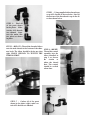
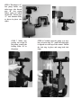
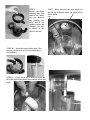
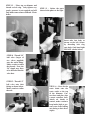
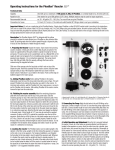
TERMINATOR II
D & D Marine Enterprises Inc. , 176 Tracy Lane, Bagdad KY 40003
www.danddmarine.com
502-747-8562
Parts Diagram
Check this diagram against your parts
PLEASE READ THIS FIRST
PLEASE READ THE ENTIRE MANUAL BEFORE BEGINNING TO
ASSEMBLE YOUR SKIMMER.
CAREFULLY STUDY THE PHOTOGRAPHS, YOU MUST PAY SPECIAL ATTENTION TO THE PHOTOS TO MAKE CERTAIN THAT
YOU HAVE THE PROPER PARTS, AND THAT WHEN ASSEMBLED THE ASSEMBLY LOOKS EXACTLY AS IN THE PHOTOS.
STEP 2 - Using supplied teflon thread tape,
wrap ALL threads as shown below. Start at
the bottom of the thread and wrap in the direction shown below.
STEP 1 - Find all
of the parts shown
in the photo . Make
certain ALL threads
are tefloned. Separate the union into
two pieces as shown
in photo.
STEP 3 - (BELOW) Thread the threaded elbow
onto the male thread at the bottom of the skimmer body. The elbow should be facing up when
tight. MAKE CERTAIN TO TEFLON THE
THREAD FIRST.
STEP 4 - (RIGHT)
Thread the venturi
assembly into the
elbow installed in
step 3, as shown.
Be
certain
to
teflon the thread
first. The venturi
should be vertical
when done.
A
C
B
STEP 5 - Gather all of the parts
shown in the photo (right), make certain ALL threads are tefloned.
D
STEP 6 Thread part “A”
into pump intake, use
teflon tape. Also thread
part “B” into pump
outlet, again use teflon
on threads. Thread part
“C” onto skimmer body
as shown in photo (far
right).
C
B
C
A
D
STEP 7 While supporting the weight of
the pump, connect the
locking collar “D” to
the pump.
D
STEP 8 Carefully turn the pump (you may
have to loosen ring “D” ) until the outlet pipe
is aligned over the top of the venturi. Thread
the lock ring in place and snug both lock
rings.
STEP 9
Remove the Black
retaining ring and
remove the skimmer top. Remove
any packing material and if not
installed insert the
skimmer core tube
as shown in the
photo to the left.
STEP 10 - Insert the return intake tube. This
presses into the back of the external fitting as
shown below.
STEP 11 - Gently screw down the nylon screw until it just contact the plastic lip as shown below and
right.
NOTE: When inserting the core, align it so
that the lip is directly under the outlet hole as
shown below.
Lip
STEP 12 - Place top on skimmer and
thread on lock ring. Only tighten very
gently, pressure is not required and will
only make removal more difficult. Photo
below.
STEP 13 - Gather the parts
shown in the photo to the right.
Insert tube into body as
shown on the left. Secure
by threading lock ring
onto body. Only hand tight
PLEASE. (shown below)
STEP 14 -Thread 3/4”
ball valve (larger of
two valves supplied)
onto the outlet fitting.
Make certain to teflon
the threads. Note, the
3/4” nipple may have
to be threaded into the
valve first.
STEP 15 - Thread 1/2”
ball valve onto inlet
fitting as shown below.
Make certain to teflon
threads.
STEP 16 - Press fit the
waste drain onto the
waste outlet at the top
of the skimmer. Connect hose and place into
a waste container. (left).
Attach air intake to
venturi, make certain to
keep intake high to prevent water from leaking
out during a shut down.
(right)
STEP 17 - The water level in the unit is controlled by adjusting the overflow tube height.
This is done by loosening the bottom nut and
sliding the clear tube up or down as shown below. Preset the water level by setting the tube
level with the bottom of the decal as shown to
the right.
Final connections
A 300 gph powerhead pump (Maxijet 1200
for example) must be hooked up to the water
inlet assembled in step 15. The valve is used
to control the process water flow rate through
the unit. The water is usually pumped from
a sump. Hook up the supplied air line to the
venturi and run it to the top of the unit to prevent water spitting out of the air intake when
power is off. Make certain that the return water valve (shown on the right) is returning to the
sump, and the valve is wide open. Make certain
the waste hose is in a waste container. Use the
supplied 1/2” x 18” hose and place it into a 1
gallon milk jug or some container.
Start up
STEP 18 - The outflow tube can be moved up or down
by loosening the upper nut and sliding as shown below.
The position may be turned to any direction and the
height may be adjusted. The outflow may be hard piped
if desired or using hose. This water must return into a
sump.
Plug in the small 300 gph pump bringing water from the sump into the skimmer first. As the skimmer fills
check all of your connections for leaks. The skimmer will fill until the water reaches the top of the overflow
tube preset in step 17. Once water is flowing back into the sump plug in the main pump. The pump may
take a few seconds the first time to prime itself. If it does not prime itself then suck air out of the venturi
air intake line. The venturi should begin to force air into the skimmer. By slowly closing the large outlet
valve, shown in step 18, raise the water level about 1 to 2 inches above the black plastic shown in the step
18 photo. This prevents water noise as the unit flows back into the sump. You may also adjust the water
level in the concentrator top shown in step 17. By simply moving the 1 1/2” tube preset to the decal in step
17 you will change the water level. This effects how wet or dry your foam will be. We recommend the water
level be approximately at the top of the decal. Fine adjustment can be done with the water inlet valve.
Limited Lifetime Warranty
Your D & D Marine Enterprises product has been built to the highest
quality and standards. It should be treated with the same care as
any fine instrument.
Limited lifetime warranty
If your D & D Marine Enterprises Inc. products has been manufactured using UniMax technology. ( This will be indicated on box labels
as well as instruction manuals.). D & D Marine Enterprises will warrant any UniMax welds to be free from defect or leaks for the lifetime
of the product and to the original purchaser. D & D Marine will repair or replace ( at its option ) your product free of charge within the
first year. During the remainder of this warranty a fee will be charged for the cost of return shipping only.
5 YEAR PRODUCT WARRANTY
Your D & D Marine Enterprises product is warranted to be free of defects in workmanship and materials for 5 years from date of
purchase. This warranty applies only to products purchased from an authorized dealer. In case of product defect in either workmanship
or materials, D & D Marine will repair or replace ( at its option ) your product free of charge within the first year. The following four years
A fee will be charged for the cost of return shipping only.
WHAT YOUR WARRANTY DOES NOT COVER
Your D & D Marine product warranty does not cover damage or failure resulting from:normal wear, accidents, misuse or abuse,
lack of reasonable care, lose of parts, abnormal usage, faulty installation, improper maintenance, or the alteration or affixing of any
unauthorized attachments. Your warranty does not extend to costs of removal or reinstallation of the product. Nor does it cover any
consequential damage.
HOW TO OBTAIN WARRANTY SERVICE
IF WARRANTY SERVICE IS REQUIRED, SEND YOUR PRODUCT WITH THE ATTACHED
REGISTRATION CARD. YOU MUST FILL IN THE SERIAL NUMBER ON THE CARD FOR WARRANTY
SERVICE TO BE PROVIDED. PROOF OF PURCHASE MUST BE ATTACHED WITH A CLEAR DATE OF
PURCHASE. IF THE UNIT IS BEYOND THIS FIRST YEAR OF WARRANTY SERVICE A CHECK FOR
$15.00 MUST BE INCLUDED TO COVER RETURN SHIPPING.
D & D MARINE ENTERPRISES INC.
176 TRACY LANE
BAGDAD KY 4000
502-747-8562
WWW.DANDDMARINE.COM
WARRANTY SERVICE CARD (Return with product for service)
Name;_______________________________ Phone number (day time)____________________________
Street; ______________________________ City; _______________________ State; __________
Zip Code; ________________ Store where purchased & Address _______________________________
________________________________________________________________________________________