1
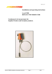
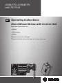
A35AE FU-A150AE FU
with TST FUS
en
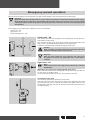
Operating Instructions
Direct Mount Drives with Control Unit
Important information for:
• Fitters
• Electricians
• Users
Please forward accordingly!
These instructions must be kept for future reference.
Assembly and Operating Instructions
Table of Contents
Introduction................................................................................................................................................................. 3
Warranty...................................................................................................................................................................... 3
Intended use............................................................................................................................................................... 3
Safety instructions....................................................................................................................................................... 4
Product overview and dimensions................................................................................................................................. 6
Installation................................................................................................................................................................... 7
Electrical connection ................................................................................................................................................... 8
Emergency manual operation.......................................................................................................................................11
Operator controls....................................................................................................................................................... 13
General operating instructions on parameterisation...................................................................................................... 14
Reset of control unit................................................................................................................................................... 15
Checking the direction of movement............................................................................................................................ 16
Setting of the door final positions................................................................................................................................ 17
Setting of the ramps and door leaf speed..................................................................................................................... 18
Fine tuning of the finish positions and control of pre-limit switch..................................................................................... 23
Electrical connection/operation of external control devices and safety devices............................................................... 23
Connection and function of the switching outputs......................................................................................................... 25
Installation and functioning of the radio control receiver................................................................................................ 26
Installation and functioning of the induction loop evaluator............................................................................................ 27
Parameter................................................................................................................................................................. 28
Overview of messages................................................................................................................................................ 30
LED display codes...................................................................................................................................................... 35
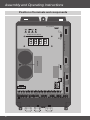
Position of terminals and components......................................................................................................................... 36
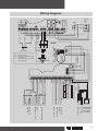
Wiring diagram.......................................................................................................................................................... 37
Maintenance............................................................................................................................................................. 38
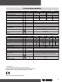
Drive technical data.................................................................................................................................................... 39
Control unit technical data.......................................................................................................................................... 40
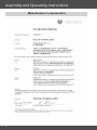
Manufacturer's declaration......................................................................................................................................... 42
2
Introduction
The A35AE FU-A150AE FU direct mount drives and TST FUS control unit are high-quality products with numerous features
and advantages.
When installing the equipment and setting the functions, please observe these Operating and Installation Instructions.
Warranty
Structural modifications and incorrect installation which are not in accordance with these and our other instructions can result
in serious injuries, e.g. crushing of limbs. Therefore, structural modifications should only be carried out with our prior approval
and in accordance with our instructions, particularly the information contained in these Assembly and Operating Instructions.
Any further processing of the products which does not comply with their intended use is not permitted.
The end product manufacturer and fitter have to ensure that all the current statutory, official regulations and, in particular,
EMC regulations are adhered to during utilisation of our products, especially with regard to end product assembly, installation
and customer advice.
Intended use
The A35AE FU-A150AE FU direct mount drives in connection with the TST FUS control unit are intended only for use indoors
for the operation of roller doors, vertical lift gates, sectional doors, sheet gates or indirectly operated door systems.
For outdoor use, special connection cables are required, and if PVC connection lines are used, these must be channelled
through a protective pipe. Use other than or beyond this is not regarded as intended use.
Other applications, utilisation and modifications are not permitted in order to protect the safety of the users and others, since
these actions can impair the system’s safety, resulting in personal injuries and property damage. Becker-Antriebe shall not
accept liability for damages arising from such actions. Always observe the information in these instructions when operating or
repairing the system. Becker-Antriebe shall not accept liability for damages resulting from incorrect usage.
3
Assembly and Operating Instructions
Safety instructions
The following safety instructions and warnings serve to avert dangers and to prevent personal injuries and damage to property. Please retain these instructions for future reference.
•
•
•
•
•
•
•
•
•
Caution
Denotes a potentially hazardous situation. If this is not avoided, injuries can
result.
Attention
Denotes a potentially hazardous situation. If this is not avoided, the product
or property in its vicinity can be damaged.
Note
Denotes hints for use and other useful information.
Important safety instructions.
Caution Ignoring this information can result in serious injuries.
The safety instructions in EN 12453, EN 12445, EN 12978, VDE 0100, EN 50110, EN 60204,
EN 50178, EN 60335 and BGR 232 and fire and accident prevention regulations must be observed.
Work on the electrical installation, electrical or electronic systems and equipment may only be carried out by a
qualified electrician.
When electrical or electronic systems or equipment are operated, certain components are live and therefore
dangerous. If unqualified persons intervene or the warnings are ignored, physical injuries or damage to property could ensue.
All the applicable standards and regulations for electrical installations must be observed.
Only spare parts, tools and additional equipment approved by the manufacturer can be used.
The manufacturer or provider is not liable for damage to persons or property or any consequential damage if
non-approved third-party products are used or changes are made to the accessories.
The thresholds specified in the technical data must not be exceeded.
When installing the drive at a height of less than 2.50 m, the drive must be covered as touching the motor can
cause burns.
There must be a sufficient safety distance between the drive and flammable materials.
The door system must be protected against crashing down.
• In the case of direct mount drives for use on a roller door, vertical lifting gate, sectional door or indirectly
operated door system, the customer must provide a suitable device (external safety catch, unwinding stopper) to reliably prevent the door from crashing down if the load carrier (e.g. cable or chain) fails.
• In the case of direct mount drives with a disconnecting clutch (AK) for use on a sectional door with spring
compensation or a counterweight, it is imperative to install a spring fracture or crash safety device to prevent the door crashing down.
• In the case of direct mount drives with a light chain (LK) or hand crank (HK), it is necessary to ensure that if
the spring fractures or the weight counterbalance fails, the torque on the drive is less than the static holding
torque specified in the technical data.
•
•
•
•
•
•
4
If this is not the case, a safety device (anti-drop device) has to be installed when using this type of drive to
prevent the door from falling down.
Opening the control device is only permitted if the power supply is turned off for all poles.
If the potential-free contacts of the relay outputs or other contact points are supplied externally, i.e. operated
with dangerous voltage which may still exist even after the control unit has been turned off or the plug has been
pulled out, a clearly visible warning label must be attached to the control unit housing. ("CAUTION! All electric
circuits must be turned off before you access the connection terminals.")
Operating the control unit when open is not permitted.
Operating the control unit with the CEE connector removed is only permitted if the electrical supply can be disconnected from the control unit for all poles by means of a switch. The plug or switch used in place of this must
be easily accessible.
If the connection line of this unit is damaged, it must be replaced by the manufacturer or its customer service
team or a similarly qualified person in order to avoid dangers.
Even after the power supply has been turned off, there is still dangerous voltage on the intermediate circuit condensers for up to five minutes. The time needed for the voltage to fall below 60VDC is a maximum of 5 minutes.
It is dangerous to touch internal parts of the control unit during this discharge time.
• If the switched mode power unit is faulty, the time needed by the interim circuit condensers to run down to a
voltage of less than 60VDC can be much longer. In this case, discharging can take up to 10 minutes.
• In the event of short-circuited or extremely overloaded 24V control voltage, the switched mode power unit does
not start, even though the interim circuit condensers are charged. The display and LEDs are off. It is only possible to start the power unit once the short circuit or extreme overload has been eliminated.
• Once the power supply has been turned off, the power unit is still supplied for a few seconds from the interim
circuit condensers and can supply power for a certain period, depending on the power unit load. In this case,
glow lamp V306 is on until the voltage has dropped.
• The processor circuit with seven segment display, EPROM and multiplexers is galvanicly connected with the
mains supply. This must be taken into consideration if any control measurements are taken (a measuring device
with PE cover on the shunt circuit must not be used for measurements in the processor circuit).
• The control unit must not be operated without a connected protective conductor. If the protective conductor
is not connected, dangerously high voltage occurs on the control housing, caused by leakage capacities. The
protective conductor must be connected in accordance with EN50178 section 5.2.11.1 for leakage currents of
>3.5mA.
• A dew-covered control unit must not be switched on/operated, as the control unit could be destroyed.
• If the control units are used outside the specified temperature range, a regulated and monitored heating system
that maintains the specified temperature when the power supply is switched on and the control unit is operated
must be ensured.
• Operation of the control unit with a damaged key pad or vision panel is forbidden. Damaged key pads and windows must be replaced. To avoid damage to the key pad, pointed objects must not be used to operate it. The
key pad is designed to be operated by fingers only.
• The first time the power supply to the control unit is switched on, it is necessary to ensure that the evaluation
cards (plug-in modules) are in the correct position. If the cards are plugged in in the wrong position or way, or
unapproved cards from third-party manufacturers are used, the control unit may be damaged.
• If the door is operated in dead-man mode, it is necessary to ensure that the operator can view the door area, as
safety devices such as the safety edge and photoelectric barrier do not take effect in this operating mode.
• The parameter settings and functioning of the safety devices must be checked. The parameter settings, bridging and other operating elements may only be carried out by trained staff.
5
Assembly and Operating Instructions
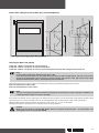
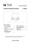
Product overview and dimensions
All dimensions in mm.
Direct mount drive with hand crank (HK)
Direct mount drive with light chain (LK)
Direct mount drive with disconnection clutch (AK)
Hole pattern
For door shaft Ø 30 mm
Control unit TST FUS
T = 120
6
For door shaft Ø 25.4 mm
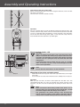
Installation
Drive installation
Attention
The direct mount drive has to be mounted on a vibration reducing mounting or torque supporting plate
with adequate stability. Indirectly driven drives should not be mounted on a vibration reducing mounting. The maximum fastening torque for the M8 bolts used for fastening the drive must not exceed 25 Nm
with a screw-in depth of 10 mm. If this is not observed, the product or something in its vicinity may be
damaged.
Before the direct mount drive is mounted on the door shaft, this must be lubricated in the drive area.
Control unit installation
Install the control unit so that the operator controls are readily accessible.
Caution
• Before installation, the control unit must be checked for transport damage or other damage. In
certain cases, damage to the internal area of the control unit can result in considerable subsequent
damage to the control unit or even pose a health threat for the user.
• Touching electronic parts, particularly the parts of the processor circuit, is forbidden. Electronic components can be damaged or destroyed by electrostatic discharging.
• Before opening the housing cover, ensure that no drilling chips on the cover can fall into the housing.
• Ensure that the control unit is installed free from distortion.
• Cable entries that are not used must be closed using suitable measures to ensure IP54 housing
protection.
• The cable entries must not be subject to any mech. load, in particular tensile load.
• The CEE connector must be well visible and accessible from the control unit.
300
Min. 100 mm
50°C
80
1 x 230 V AC,
N, PE
160
Min. 100 mm
approx. 1300
-10°C
Opening, assembly of the cover and connection of the key pad
7
Assembly and Operating Instructions
Electrical connection
Caution
Electrical connection may only be carried out by a qualified electrician. Please observe the information
on the control unit to be used and the applicable VDE standards. Prior to any connection work, ensure
that the door system is correctly disconnected from the power supply by removing the CEE connector/
switching off the main switch. Please observe the technical data of the direct mount drive. The thresholds
specified in the technical data must not be exceeded. In particular the door system protection provided
by the customer has to be carried out in accordance with the technical data.
When laying the protective conductor, please ensure that the contract of the protective conductor is interrupted last when the cable is pulled out unintentionally. Subsequently lay the connection cable so that
this is not touching the drive.
There is still dangerous voltage up to 5 minutes after the control unit has been switched off. It is dangerous to touch electronic parts because of residual voltage. The control unit must never be operated with
an open housing cover. After the wiring has been carried out and before the control unit is switched on for
the first time, check whether all motor connections are tight/properly corrected on the control unit and
motor side. Loose motor connections usually damage the converter. All control voltage inlets are galvanically separated from the power supply by basic insulation. All components to be connected to the control
units must have additional insulation with a rated voltage of > 230 V (in accordance with EN 60335-1).
The plug must be visible and accessible from the control unit.
Attention
Very high electrostatic charges occur particularly on fast sheet gates. Discharging this can cause damage to the control unit. Suitable measures to prevent electrostatic charging must therefore be carried
out.
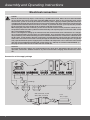
Connection of the supply voltage
4 windings
CEE-connector, 3-pole
300 / 500 / 16 A, blue
Fuse
16 A / K type
L
N
PE
8
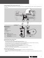
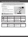
Connecting the drive to the control unit
bw
br
gr
To connect the direct mount drive to the control unit, only use original control and motor cables approved by the.
manufacturer.
gn/ye
6
Electrical interface:
AMP connector
1 - Safety chain inlet
2 - RS485 B
3 - GND
4 - RS485 A
5 - Safety chain outlet
6 - 7..18 V DC
Protection of the
motor cable
WAGE terminal
7/8
- S4F Thermal switch
9/10
- S3F Safety limit switch HK/LK
(bridged at AK)
11/12 - Connection option for external
safety elements
4
gr br bw
gn/ye
S4F
S3F
(optional)
Connection of the control unit
Connection of the control cable
• Unscrew the oval, black screw holding devices from the screw.
• Now separate the two parts of the screw holding device from each other
• Put the cable with the terminals and the thicker part of the screw holding device through the right oval opening.
• Fit together the halves of the screw holding device on the housing wall.
• Loosen the screw coupling ring so that the screw can be turned on the cable.
• Now screw the screw tightly into the screw holding device.
• Push the cable into the control unit until the casing is around 0.5 cm into the control unit.
• Tighten the coupling ring to ensure protection.
• Connect to terminals 60/61 and 80/81/82/83 in line with the diagram above.
Connection of the motor cable
The motor cable is connected in the same way as the control cable with the following differences:
• Insert the motor cable through the left oval opening.
• Connect to terminal T1/T2/T3 in accordance with the diagram above and tighten the two green/yellow wires on the PE.
terminal.
9
Assembly and Operating Instructions
Connection of the drive
Opening of the limit switch box
If necessary, remove the bolts at the yellow lock bars and carry out steps 1 – 4.
1.
2.
3.
4.
The control and motor cables can be inserted on the drive side. To ensure that the tension relief and protection class of the
drive are guaranteed, the screws must not be loosened. The connectors are protected against reverse polarity and there is an
audible click when they engage.
Note
The green/yellow protective conductor wires must be connected to the designated push-on connector
. Please ensure that it clicks into place properly.
Connection of the control cable
Connection of the motor cable
Closing of the limit switch box
Use the previously removed bolts or the bolts supplied in the casing cover and carry out steps 1 – 6 shown below.
Note
Please ensure that the seal and the lining groove are clean and that the cover has been placed correctly.
1.
2.
3.
4.
Caution
If the drive is installed at a height of less than 2.50 m, the yellow latches must be secured using the enclosed screws.
5.
6.
Carefully tighten the screws.
10
Emergency manual operation
With the aid of emergency manual operation, the door can be opened or closed in the event of a power failure.
Attention
Before emergency manual operation is used, the door system must be disconnected from the power supply.
Manual emergency operation is only allowed with the motor turned off, via hand crank, and can only be
carried out by the service technician or instructed personnel. The door must not be moved beyond the
final position.
For emergency manual operation, 3 different systems are available:
• Hand crank – HK
• Light chain – LK
• Disconnecting clutch – AK
Hand crank – HK
First remove the cover. For emergency manual operation, the hand crank is
inserted in the motor shaft.
This activates the S3F safety switch to ensure that electrical operation of the
door system is prevented during emergency manual operation.
The door can be opened or closed by turning the hand crank.
Caution
After operation, the hand crank must be removed, otherwise
injuries or damage to property may occur.
Attention
After the hand crank has been removed, the cover must
be replaced to ensure the protection class of the drive is
retained.
Light chain – LK
Note
Direct mount drives with a light chain (LK) must be mounted
horizontally.
Mounting of the chain wheel with integrated chain guard.
Mount the chain wheel with the integrated chain guard so that the side that
has the sticker is facing the drive.
Fix the chain guard using a flat washer, spring washer and screw.
Introduction of the chain
Turn the chain guard so the openings face upwards.
Take one end of the chain and insert this into the left opening of the chain
guard. Ensure the chain is properly positioned in the guide. Then turn the
chain guard to the right until you are able to pull the end of the chain out of
the other opening.
11
Assembly and Operating Instructions
Connection of the ends of the chain
Before connecting the ends of the chain using the chain lock, make sure that
the chain is not twisted.
The chain lock must be fastened carefully.
Operation
You can manually open or close the door by pulling the relevant chain. This
activates the S3F safety switch to ensure that electrical operation of the door
system is prevented during emergency manual operation. After operation,
ensure that the chain hangs freely again, so that the S3F safety switch is
released and electrical operation is possible again.
Disconnecting clutch – AK
Approx. 150mm
Attention
When using direct mount drives with a disconnecting clutch
(AK) on a sectional door with spring compensation or a counterweight, it is imperative to install a safety device (anti-drop
device in case of a spring fracture) to prevent the door from
falling down.
A disconnecting clutch should only be used on sectional
doors if the door system is fully counterweighted and the
drive is not in operation.
Decouple
Couple
Note
Ensure that the chain wheel is on the left buffer.
Mounting of the chain and chain guard
- Mount the chain so that approx. 150 mm is suspended freely on the righthand side.
- Push the chain on to the chain wheel hub until it audibly clicks into place.
Operation
When you pull the chain, the drive is decoupled from the door shaft. The
counterbalanced door can now be opened and closed manually. After
operation, the drive must be coupled again by pulling the other end of the
chain.
Note
Make sure that the lower final position of the door is set so
that the cables for suspending the door remain taut, i.e. that
the entire weight of the door hangs on the cables.
This guarantees the smooth running of the disconnecting
clutch. Incorrect settings (slack cable) in the lower final position prevent smooth running of the disconnecting clutch.
12
Operator controls
Button
Button
Å
Button
Pressing the UP button opens the door. When the upper final position has been reached or if a safety function responds, the
door stops automatically. If the UP button is pressed whilst the door is closing, the door stops and after a short delay it moves
to the upper final position.
Pressing the STOP button stops the door instantly when it is opening or closing. An error can also be acknowledged and reset
by pressing the button for a longer period.
Pressing the DOWN button closes the door. When the door reaches the lower final position, it stops automatically. If the safety
edge or photoelectric barrier responds, the door stops and then continues to the upper final position. Pressing the DOWN
button while the door is opening has no effect.
EMERGENCY STOP switch (optional)
If the EMERGENCY OFF button is pressed, the drive is switched off. Door movement is only possible again after releasing the
EMERGENCY STOP button.
13
Assembly and Operating Instructions
General operating instructions on parameterisation
Three operating levels are available for changing the parameters (P.999: 0-2) see Parameter Overview section.
Once optimum door running has been set, you go from operating level 2 to 1. This means you cannot change the door running by mistake.
Change parameters
Proceed as follows to change parameters:
•
•
•
•
Pull out the power plug
Turn DIP switch S200 to ON.
Put the power plug back in.
Press the Å STOP and UP buttons simultaneously for
about 3 seconds to go to parameterise mode for door
control.
• Change the parameters as required.
• Once you have made the settings, exit parameterise
mode by pressing the Å STOP button for about 3 seconds.
S200
Caution
Once you have changed the parameters, set
DIP switch S200 to OFF.
Start parameterise modes
1.
2.
Switch of door
control
S200
3.
7-segment display disappears
after a delay of a few seconds.
Switch the S200 Service mode is deactivated,
switch to ON
close housing.
Switch on door
control
4.
Switch off supply for all poles
(note safety instructions).
Å+ Stop + UP (long)
When service mode is active, the
initial decimal point flashes.
Switch on control unit.
Display depends on control
state.
After about 3 seconds control
Press Stop button and Up button
will switch to parameterise
for a long time.
mode.
.
.
.
.
P.
0
0
0
P.
.
Parameter selection
14
UP
or
DOWN
Select the required parameter.
CAUTION:
The parameter value can be
Not all parameters can be viewed/ viewed or changed (see below)..
changed directly. This depends
The display differs depending on
on the selected operating level
your selection.
(P.999: 0-2).
.
.
Parameter editing
1.
2.
3.
or
4.
Control in parameterise mode.
1
0
Opening of the parameter.
Up
Up button to increase parameter
value.
Down
Down button to decrease para
meter value.
Å
STOP (long)
Save defined parameter value.
The parameter has been saved
when all the points stop flashing.
6
STOP (short)
Discard defined parameter value.
Termination, the original para
meter value is displayed.
4
STOP (short)
Go to display of parameter name. Display of parameter name.
Å
1.
Å
2.
4.
0
STOP (short)
Exit parameterise mode
3.
P.
Å
or
5.
Display of the required para
meter name.
The current parameter value is
displayed.
S200
5
If the currently valid parameter
value is changed, the decimal
points flash.
STOP (long)
Parameterise mode is cancelled
immediately, door operation is
active again.
The last value saved is automatically retained.
Switch of door
control
Switch off supply for all poles
(note safety instructions).
7-segment display disappears
after a delay of a few seconds.
6
4
P.
0
1
0
.
.
.
.
Switch the S200 Service mode is deactivated,
switch to OFF
close housing.
Switch on door
control
Switch on control unit.
Note
Service mode is automatically reset after about 1 hour. To return to service mode, the control unit must
be switched off briefly and then switched back on or a reset must be carried out.
Reset of control unit
Å++ simultaneously for about 3 seconds.
15
Assembly and Operating Instructions
Checking the direction of movement
Move the door into semi-opened position using emergency manual operation.
Insert the control unit’s CEE connector into the socket, or turn on the control unit’s main switch.
The drive specifications are already stored in the control unit. The control unit is currently in „Calibration“ mode (dead-man
mode), which is indicated on the display by the message „EICH“.
The drive's rotation direction depends on the control unit and must first be checked. Proceed as follows:
• Check whether the door is in semi-open position.
• Check whether the control unit is in EICH mode. If it is not, proceed as follows:
1. Start parameterise mode by simultaneously pressing the Å STOP and UP button (long).
2. Access parameter P.210 Reprogram all Final Positions by pressing the arrow buttons.
3. Access the parameter by briefly pressing the Å STOP button and use the arrow buttons to select value 5 and
then save with the Å STOP button (long).
4. When you have changed the parameter, exit parameters P.210 parameterise mode by pressing the Å STOP button for
a long time.
The message "EICH" is shown on the display.
Note
In future, this procedure will be shown as follows:
P.210: 5
• Press the Å STOP button (short) to confirm EICH mode.
The message "E.i.E.u." is shown on the display.
• Use the UP and DOWN buttons on the control unit to determine whether the door's direction of movement matches that of
the button you pressed.
Note
If the door does not move, the motor does not have enough power. You can use the boost (increase in
performance at low speeds) to give the motor more power.
Boost/performance increase at low speeds
The boost is used to improve the drive performance at low speeds. An error in door running can occur if the boost setting is
too high or too low. The setting range for the boost is 0-30%. If the boost is too high, this results in an overcurrent error (F.510/
F.410). In this case, the boost must be reduced. If the boost is low or 0 and the motor does not have enough power to move
the door, the boost must be increased.
Because of the numerous types of door, the correct boost setting must be determined by trial and error.
Boost for moving up: P.140: 0-30 %
Boost for moving down: P.145: 0-30 %
Note
You can use diagnosis parameter P.910: 2 to display the current motor current. The boost should be set
so that the motor current is as low as possible.
• If the door's direction of movement does not match the button commands, change the direction as follows: •
P.130: 0 = right rotation field
Check the direction of movement again.
16
Setting of the door final positions
Caution
Each time you change the door final positions, you must then fine tune the final positions and check the
pre-limit switch.
Note
If the final positions were programmed in advance, programming of the final positions must be requested
again.
To do this, set the following parameters:
P.210: 5 = Reprogramming of all final positions
The drive has an absolute value encoder, which detects the door final positions via the control unit.
Attention
It is not possible to define the settings for this absolute value encoder in the drive.
Before the door final positions are programmed, the door safety edge must be connected to the TST
FUS door control unit (see the "Electrical connection/operation of external control devices and safety
devices" section).
The door final positions are set directly in the control unit.
Ensure that the message "E.i.E.u." is shown on the display.
The control unit is in dead-man mode.
• Move the door to the required lower final position.
• Save the final position by pressing the Å STOP button (long).
The message "E.i.E.o." is shown on the display.
• Move the door to the required upper final position.
• Save the final position by pressing the Å STOP button (long).
The message "E.i.E.o." is shown on the display.
• If you do not want to set a partial opening position, press the Å STOP button (long).
The message "-Eo-"
• If you want to set a partial opening position, move the door to the required position.
• Save the partial opening position by pressing the Å STOP button (long).
The message "STOP" is shown on the display.
The control unit requires several adjustment runs before the final positions can be reached at full operational speed. During
the adjustment runs, the final positions that are set are intentionally not reached and message "I.5XX" is displayed.
Move the door towards the final positions until the message "I.510, _Eu_ or -Eo-" is displayed.
Setting of the final positions is then complete.
17
Assembly and Operating Instructions
Setting of the ramps and door leaf speed
Caution
Each time you change the door leaf speed or ramps, you must then fine tune the final positions and check
the pre-limit switch.
Setting of start and brake ramps
Note
Changing the ramps (P.39F) resets the frequencies for movement up and down (P.310/P.350) to the factory setting (60Hz/ 40Hz).
P.39F: 0 = average/slow acceleration of the door
P.39F: 1 = slow acceleration of the door (large, heavy door)
P.39F: 2 = average acceleration of the door
P.39F: 3 = fast acceleration of the door (small, light door)
18
Movement down
P.39F
Start ramp
Brake ramp
Speed moving down
P.350
Movement up
P.39F
Brake ramp
Start ramp
Speed moving up
P.310
Doors with a height of less than 4m
P.39F
Movement up
Start ramp
Brake ramp
Speed moving down P.365
Brake ramp
Pre-limit switch P.226
Speed moving down P.350
Movement up
P.39F
≥ 2,50 m
Brake ramp
Start ramp
Speed moving up
P.310
Doors with a height of more than 4m (recommendation)
Setting the door leaf speed
P.310: 20 - 100 Hz = frequency for speed moving up
P.350: 20 - 100 Hz = frequency for speed moving down
P.365: 20 - 100 Hz = frequency for second speed moving down for door with a height of more than 4 m
Note
Increase the frequency in small intervals (max. 5 Hz)
If the door does not move or is very slow, the motor does not have enough power. You can use the boost
(increase in performance at low speeds) to give the motor more power. If the door moves very slowly
despite maximum boost (30 %), the frequency must be reduced.
Because of the numerous types of door, the correct boost setting must be determined by trial and error.
Boost for moving up: P.140: 0-30 %
Boost for moving down: P.145: 0-30 %
Note
You can use diagnosis parameter P.910: 2 to display the current motor current. The boost should be set
so that the motor current is as low as possible.
The control unit requires several adjustment runs before the final positions can be reached at full operational speed. During
the adjustment runs, the final positions that are set are intentionally not reached and message "I.5XX" is displayed.
Move the door towards the final positions until the message "I.510, _Eu_ or -Eo-" is displayed.
Setting of the door leaf speed and start and brake ramps is now completed.
Caution
Make sure you observe standard EN 12445: Safe use of power-operated doors - test procedure. The
closing force can be no more than 400 N.
19
Assembly and Operating Instructions
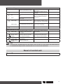
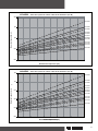
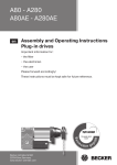
A35AE/112
- Door
Torblattgeschwindigkeiten
diverse
Seiltrommeldurchmesser
(ST-ø)
leaf speed for variousfür
cable
drum
diameters (ST-Ø)
3,50
ST-ø350
3,00
ST-ø300
ST-ø280
Door
leaf speed [m/s][m/s]
Torblattgeschwindigkeit
2,50
ST-ø250
ST-ø235
2,00
ST-ø216
ST-ø203
ST-ø188
1,50
ST-ø146
ST-ø134
ST-ø102
1,00
0,50
0,00
30
40
50
60
70
80
Movement
frequencies
Fahrfrequenzen
[Hz] [Hz]
A50AE/90
3,00
- Door
Torblattgeschwindigkeiten
diverse
Seiltrommeldurchmesser
(ST-ø)
leaf speed for variousfür
cable
drum
diameters (ST-Ø)
ST-ø350
2,50
Door
leaf speed [m/s] [m/s]
Torblattgeschwindigkeit
ST-ø300
ST-ø280
2,00
ST-ø250
ST-ø235
ST-ø216
ST-ø203
ST-ø188
1,50
ST-ø146
ST-ø134
1,00
ST-ø102
0,50
0,00
30
40
50
60
Movement
frequencies
Fahrfrequenzen
[Hz][Hz]
20
70
80
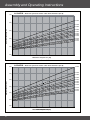
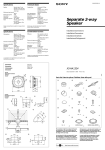
A70AE/60
2,00
Door leaf speed for variousfür
cable
drum
diameters (ST-Ø)
- Torblattgeschwindigkeiten
diverse
Seiltrommeldurchmesser
(ST-ø)
ST-ø350
ST-ø300
Door
leaf speed [m/s] [m/s]
Torblattgeschwindigkeit
1,50
ST-ø280
ST-ø250
ST-ø235
ST-ø216
ST-ø203
ST-ø188
1,00
ST-ø159
ST-ø146
ST-ø134
ST-ø102
0,50
0,00
30
40
50
60
70
80
Movement
frequencies
Fahrfrequenzen
[Hz][Hz]
A80AE/40
1,25
Door leaf speed for variousfür
cable
drum
diameters (ST-Ø)
- Torblattgeschwindigkeiten
diverse
Seiltrommeldurchmesser
(ST-ø)
ST-ø350
ST-ø300
Door
leaf speed [m/s] [m/s]
Torblattgeschwindigkeit
1,00
ST-ø280
ST-ø250
ST-ø235
ST-ø216
ST-ø203
0,75
ST-ø188
ST-ø159
ST-ø146
ST-ø134
0,50
ST-ø102
0,25
0,00
30
40
50
60
70
80
Movement
frequencies
Fahrfrequenzen
[Hz][Hz]
21
Assembly and Operating Instructions
A110AE/30
1,00
leaf speed for variousfür
cable
drum
diameters (ST-Ø)
- Door
Torblattgeschwindigkeiten
diverse
Seiltrommeldurchmesser
(ST-ø)
ST-ø350
0,80
Door
leaf speed [m/s]
Torblattgeschwindigkeit [m/s]
ST-ø300
ST-ø280
ST-ø250
0,60
ST-ø235
ST-ø216
ST-ø203
ST-ø188
ST-ø159
ST-ø146
ST-ø134
0,40
0,20
0,00
30
40
50
60
70
80
Movement
frequencies
[Hz]
Fahrfrequenzen
[Hz]
A150AE/20
0,60
leaf speed for variousfür
cable
drum
diameters (ST-Ø)
- Door
Torblattgeschwindigkeiten
diverse
Seiltrommeldurchmesser
(ST-ø)
ST-ø350
ST-ø300
Door
leaf speed [m/s]
Torblattgeschwindigkeit [m/s]
0,50
ST-ø280
ST-ø250
ST-ø235
0,40
ST-ø216
ST-ø203
ST-ø188
0,30
ST-ø159
ST-ø146
ST-ø134
0,20
0,10
0,00
30
40
50
60
Fahrfrequenzen
[Hz]
Movement
frequencies
[Hz]
22
70
80
Fine tuning of the finish positions and control of
pre-limit switch
Note
If you increase the value, the switching point gets higher.
If you decrease the value, the switching point gets lower.
Fine tuning of the finish positions
P.231: -125 to +125 increments = adjustment value for the upper finish position
P.221: -125 to +125 increments = adjustment value for the lower finish position
Control of pre-limit switch for deactivation of the safety edge function
Caution
To check the deactivation of the safety edge function by the internal pre-limit switch VES, consult standard EN 12445: Safe use of power-operated doors - test procedure.
The max. permitted set height of the pre-limit switch to the ground can be no more than 50 mm at the
least favourable place.
To check the set height of the pre-limit end switch VES, put the VES gauge or a similar spacer (height:
50 mm) on the ground under the door at the most unfavourable place in the door opening. When the door
reaches the 50 mm high VES gauge or similar spacer, the door must stop immediately and then release
this simulated obstacle (move up). If this is not the case, you must adjust the pre-limit switch.
P.440: -60 to +999 = adjustment value for the pre-limit switch of the safety edge
Electrical connection/operation of external control devices
and safety devices
Safety edge
The following safety edge systems can be connected to door control unit TST FUS directly:
• Pneumatic safety edge (DW) or
• Electric safety edge (EL)
• Optoelectronic safety edge: FRABA OSE.
The sensor required is integrated into the control unit (self-monitoring sensor as per pr EN 12453).
The pneumatic safety edge or the electric safety edge is connected up to terminals 72 and 73 and monitored with a terminating resistor. It must be connected inside the pressure switch contact or at the end of the electric safety edge in accordance
with the wiring diagram.
In the case of factory-assembled electric safety edges, check their terminating resistance. Safety edges with a 1.2 kΩ or 8.2
kΩ terminating resistor may be used.
Connect the OSE optoelectronic safety edge made by FRABA to terminals 72, 73 and 74 directly without the need for a terminating resistor (72 - green wire, 73 - white wire, 74 - brown wire).
To modify the control unit in line with the safety edge, jumper J600 (see the section on the position of terminals and components, above right) and parameter P.460 must be set in accordance with the table below.
Type of safety edge
P.460
J600
Safety edge inactive
0
1K2
Note: This setting is only possible if a safety edge is not connected.
Electric safety edge 1,2 kOhm, normally open contact
1
1K2
Electric safety edge 8,2 kOhm, normally open contact
1
8K2
Electric safety edge 1,2 kOhm, normally closed contact
2
1K2
Electric safety edge 8,2 kOhm, normally closed contact
2
8K2
Safety edge with testing (DW) 1,2 kOhm, normally open contact
3
1K2
Safety edge with testing (DW) 8,2 kOhm, normally open contact
3
8K2
Safety edge with testing (DW) 1,2 kOhm, normally closed contact
4
1K2
Safety edge with testing (DW) 8,2 kOhm, normally closed contact
4
8K2
Optoelectronic safety edge FRABA OSE
5
1K2
23
Assembly and Operating Instructions
Caution
If a pneumatic safety edge is used, parameter P.460 must have the value 3 or 4, as otherwise the functioning of the pneumatic safety edge cannot be monitored correctly. When delivered, safety devices may
be bridged. Before initial use, always check that no non-permissible bridging exists. Parameter P.460
cannot have the value 0 as this deactivates the safety edge.
If the safety edge responds during UP movement (E.360), the door is immediately stopped by the TST FUS control unit. After
an internal period of 0.2 s (P.420: 3 - 200 [10 ms] = 30 - 2000 ms), TST FUS moves the door back to the upper final position.
Caution
Make sure you observe standard EN 12445: Safe use of power-operated doors - test procedure. After at
least 750 ms the closing force must be reduced to less than 150 N.
Note
Before connecting other external control devices you should first check the direction of door movement
and set the final positions of the door, the door leaf speed and the ramps.
EMERGENCY STOP switch/spring fracture safety device
At terminal 60, the aforementioned switches can be connect in series to wire 5 of the drive. If a switch is actuated the door
is stopped. Every additional door movement is blocked for as long as it is pressed.
Slack rope switch/wicket door switch
The aforementioned switches can be connected, if necessary in series, to terminals 70 and 71. For installation the wire jumper
across terminals 70 and 71 must be removed. This input is debounced via an internal timing element. If one of the switches
responds beyond this period, the door is stopped. Every additional door movement is blocked for as long as it is pressed.
Photoelectric barrier
A photoelectric barrier (24 V DC) can be connected to terminals 47, 48 and 49. For installation the wire jumper across terminals 47 and 48 must be removed.
This control input has two functions:
• If the photoelectric barrier responds during downward movement (E.105), the door stops instantly. TST FUS then moves
the door back to the upper final position.
• If the light beam is broken when the door is open or in the process of opening and is then released again, the Keep Open
Time 2 of 3 s (P.015: 0 - 200 s) starts running once the door reaches the upper final position.
If the photoelectric barrier is installed in the guide tracks, note that a pre-limit switch must be set to deactivate the photoelectric barrier function.
Set the following parameters to be able to read the current position value:
P.910: 9 = current position in increments
From the lower final position, move the door to the required installation height for the photoelectric barrier.
Check the position value at this point.
The installation height cannot be higher than position value 900.
Now install the photoelectric barrier.
Then move the door closing edge 20 mm to max. 50 mm above the photoelectric barrier and read off the current position
value.
Now set parameter P.441 (0-999) to the current position value.
Check the functioning of the photoelectric barrier and set parameter P.910 back to 0.
P.910: 0 = display control process
External 1-way pushbutton switch
A 1-way pushbutton switch can be connected to terminals 44 and 45. The pushbutton commands are executed one after
the other in the sequence UP (up to upper final position) / DOWN / STOP - Up.
The pushbutton commands are ignored if there is a fault.
External triple pushbutton
An external triple pushbutton can be connected to terminals 40, 41, 42 and 43 .
Caution
If you use several triple pushbuttons, the stop buttons must be switched in series. (see overall wiring
diagram).
These have the same functions as those on the keypad on the front of the control unit apart from in the following cases:
• Confirm and reset errors
• Go to parameterise mode
The jumper between terminals 40 and 42 must be removed in order to connect an external triple pushbutton.
24
Automatic closing
A switch for deactivating the "automatic closing" function can be connected to terminals 54 and 55.
If automatic closing is activated (switch open), the control unit automatically moves the door to the upper final position after the keep open time 1 of 10 s (P.010: 0 - 200 s) and to the partial opening position after the keep open time 3 of 10 s
(P.011: 0 - 200 s). If the photoelectric barrier was broken, the door automatically closes after the keep open time 2 of 3 s
(P.015: 0 - 200 s).
For P.010: 0, P.011: 0 and P.015: 0 automatic closing is deactivated.
If the early warning time before moving down (P.025 : 0 - 20 s) is set to greater than 0 s with warning light (P.700: 1) a warning is given before the start of automatic closing through actuation of relay K1.
Partial opening
A switch to activate the "partial opening" function (also referred to as 1/2 door height) can be connected to terminals 56 and
57. If partial opening is activated, the programmed partial opening position is used as the upper finish position.
Setting the partial opening position
Set the following parameters to be able to read the current position value:
P.910: 9 = current position in increments
Move the door to the required partial opening position.
Now set parameter P.240 to the current position value.
Check the set partial opening position and set parameter P.910 back to 0.
P.910: 0 = display control process
Stop in UP direction
A switch for stopping in UP direction can be connected to terminals 58 and 59. For installation the wire jumper across terminals 58 and 59 must be removed.
If the switch responds during UP movement, the door is stopped. UP movement remains locked. The switch must be released
by manually pressing the DOWN button (jogging mode). As soon as the switch is released, the door stops and switches back
to automatic mode.
Connection and function of the switching outputs
Switch outputs
The TST FUS door control unit has 3 potential-free relay switch outputs (changeover contacts, see wiring diagram) each with
a switching capacity of 230 V AC / 3 A.
Switching functions of the indicator outputs
Door status + warning light flashing
Relay K1 switches on when the door leaves either of the finish positions and flashes at a
rate of 1 Hz. If the early warning time before moving down (P.025 : 0 - 20 s) or before
moving up (P.020: 0 - 1000 [10ms]) is greater than 0 s, relay K1 switches on flashing as
soon as the early warning time starts.
Relay K2 switches on at the upper finish position.
Relay K3 switches on at the lower finish position.
When the door is moving, relays K2 and K3 are off.
Door status + yard light with time delay
At the beginning of each door movement relay K1 switches on and remains on for 120 s
(P.713: 0 - 999 =10 - 1009 s) after the end of each door movement.
Relay K2 switches on at the upper finish position.
Relay K3 switches on at the lower finish position.
When the door is moving, relays K2 and K3 are off.
P.700
1
2
25
Assembly and Operating Instructions
Installation and functioning of the radio control receiver
The TST FUS control unit can be fitted with a 1-channel radio
remote control system. If such a system has been ordered
with the control unit, the radio receiver will already have been
installed in the control unit. If this is the case, please proceed
to the "Function" section.
If a radio remote control system is being retrofitted, you must
first install the receiver board on the motherboard. For this
disconnect the entire door control system from the mains.
Insert the radio control receiver board in slot FUNK at the top
right of the TST FUS control unit, as shown on the drawing.
Make sure the board is aligned correctly.
Lay the receiver aerial in the control unit vertically downwards.
Program channel 1
Radio control receiver board
Lay radio aerial
downwards
vertically
Function
Channel 1
Channel 1 of the radio remote control operates in the same way as the 1-way pushbutton switch. The pushbutton commands
are executed one after the other in the sequence UP (up to upper final position) / DOWN / STOP - Up.
The pushbutton commands are ignored if there is a fault.
Caution
When using a radio control system the person controlling the door must have a clear view of the door and
its surrounding area during door movement and must not be in a dangerous position.
Programming the Hand-held Transmitter Code
1. Press the Transmit button on the transmitter and check whether the transmission control light is on.
2. At the bottom of the hand-held transmitter, press the long grey button with your thumb and open the hand-held
transmitter.
3. Enter the personal code on the code switch with a pen, for example.
4.
5.
•
•
Close the hand-held transmitter.
To program the hand-held transmitter code in the radio control receiver proceed as follows:
Press Program Channel 1 on the radio control receiver.
Within 5 s press the Transmit button on the hand-held transmitter that is to be programmed for channel 1 until the red LED
on the radio control receiver is on (the drive starts to run).
You can program up to 32 transmitters with different codes in this way.
Deleting all the transmitter codes programmed
Note
It is not possible to delete an individual transmitter.
To delete the hand-held transmitter codes in the radio control receiver proceed as follows:
Press Program Channel 1 on the radio control receiver for about 10 seconds until the red LED comes on.
All the programmed transmitter codes are now deleted.
26
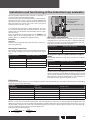
Installation and functioning of the induction loop evaluator
The TST SUVEK1 induction loop evaluator (1 channel) is a
system for inductive vehicle identification.
The TST FUS control unit can be fitted with a 1-channel induction loop evaluator. If such a system has been ordered with
the control unit, the induction loop evaluator will already have
been installed in the control unit. If this is the case, please
proceed to the "Function" section.
If an induction loop evaluator is being retrofitted, you must
first install the induction loop evaluator board on the motherboard. For this disconnect the entire door control system
from the mains.
Insert the radio control receiver board in slot SUVEK at the
bottom right of the TST FUS control unit, as shown on the
drawing. Make sure the board is aligned correctly.
Function
Channel 1
Channel 1 of the induction loop evaluator has the same function as the UP button.
Setting the sensitivity
You set the sensitivity for each channel to define which inductivity change a vehicle must cause so that the sensor output
is set.
Sensitivity level
Channel 1 DIP switch 1, 2 1 low
OFF/OFF
2
ON/OFF
3
OFF/ON
4 high
ON/ON
LED green channel 1
LED red channel 1
TST SUVEK1
(channel 1 DIP switch 1-4)
Induction loop channel 1
Setting the stopping time
The stopping time can be set using DIP switch 3. Once the
stopping time has passed, "loop free" is signalled and readjustment of the loops is automatically carried out. The stopping time starts when the loop is occupied.
Stopping time
Channel 1 DIP switch 3
5 minutes
OFF
infinite
ON
Setting the frequency and automatic readjustment
The working frequency of the sensor can be set using DIP
switch 4.
Frequency
Channel 1 DIP switch 4
low
OFF
high
ON
The permitted frequency range is 30kHz to 130kHz.
Readjustment can be triggered manually by changing the frequency setting of a channel. When the power supply is turned
on, the sensor automatically carries out readjustment for the
loop frequency. Automatic readjustment is not carried out in
the event of a short-term loss of power of <0.1s.
LED display
The green LED signals that the sensor is ready for operation. The red LED indicates activation of the relay output, depending
on the occupancy status of the loop.
LED green
Loop control
LED red
Loop status
Sensor status
off
off
No power supply
flashing
off
aut. readjustment or frequency output
on
off
Detector ready, loop free
on
on
Detector ready, signal output
off
on
Loop malfunction
Output of loop frequency
Approx. 1s after sensor automatic readjustment, the loop frequency is output via the flashing signal of the green LED. The
10kHz point is output first. For each 10kHz loop frequency, the green LED of the sensor channel flashes once. After a 1s pause,
the 1kHz point is output in the same way. If the one kHz point has the value '0', 10 flash signals are output. The 1kHz flash signals are somewhat shorter than those for the 10kHz point.
Example of 57 kHz loop frequency:
Zehner
Einer
1s
5x 10kHz
7x 1kHz
27
Assembly and Operating Instructions
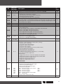
Parameter
Operating level 0 (P.999: 0; DIP switch S200 to OFF). The level 0 parameters are visible.
Operating level 1 (P.999: 1; DIP switch S200 to ON). The level 0 and 1 parameters are visible.
Operating level 2 (P.999: 2; DIP switch S200 to ON). The level 0.1 and 2 parameters are visible.
P.
000
[Cycles]
010
[s]
0..200
011
[s]
0..200
015
[s]
0..200
016
025
[s]
0..60
[10 ms]
0..1000
[s]
0..20
130
0..1
140
[%]
0..30
145
[%]
0..30
210
0..5
221
[Inc]
± 125
226
0..2100
231
[Inc]
± 125
240
310
25..9999
020
350
28
[Unit] Setting range
[Hz]
20..100
[Hz]
20..100
Description
Display of door cycle counter
Representation: 1234567 ⇒ 1234. .567
Representation: 67 ⇒ 67
Keep open time 1
Keep open time 1 starts when the door is in the upper final position.
0 = automatic closing deactivated
Keep open time 3
Keep open time 3 starts when the door is in the partial opening position.
0 = automatic closing deactivated
Keep open time 2
Keep open time 2 starts if the photoelectric barrier is broken.
0 = automatic closing deactivated
ex
works
10
10
3
No function
5
Early warning time before moving up
0
Early warning time before moving down
0
Motor rotary field
0: Right rotary field
1: Left rotary field
Boost for moving up
Voltage increase in U/f characteristic curve in % of nominal voltage when moving up.
→ Torque increase in lower speed range
Boost for moving down
Voltage increase in U/f characteristic curve in % of nominal voltage when moving down.
→ Torque increase in lower speed range
Reprogramming of final positions
0: no → None/termination
1: Eu → No function
2: Eo → Upper limit switch
3: uo → Upper and lower limit switch
4: E1 → Limit switch – partial opening
5: al
→ (All) Upper, lower and partial opening
Adjustment value lower final position
If you increase the value, the switching point gets higher.
If you decrease the value, the switching point gets lower.
(Set to 0 is the door final positions are reset)
1
5
0
0
0
Switching point between fast and normal movement down in connection with P.365
0
Adjustment value upper final position
If you increase the value, the switching point gets higher.
If you decrease the value, the switching point gets lower.
(Set to 0 is the door final positions are reset)
0
Partial opening position
25
Frequency for moving up
60
Frequency for moving down
CAUTION: Observe closing forces on safety edge.
40
P.
365
[Unit] Setting range
[Hz]
20..100
39F
0..3
420
[10 ms]
3..200
440
441
-60..999
0..999
460
-1..5
700
1..2
713
0..999
(=10..1009s)
910
0..15
920
Eb 1
Eb 2
Eb 3
Eb 4
Ebcl
Eb -
925
Description
Frequency for 2nd speed moving down in connection with P.226
Ramp profiles
0: Average/slow acceleration of the door
1: Slow acceleration of the door (large, heavy door)
2: Average acceleration of the door
3: Fast acceleration of the door (small, light door)
Reversing time when safety edge actuated
If the safety edge is actuated when the door is moving down, the door stops and is
opened again after a short period. The time between stopping and reopening is set with
this parameter. (20 = 200ms)
ex
works
30
0
20
Position of pre-limit switch safety edge
10
Position of pre-limit switch photoelectric barrier
20
Type of safety edge
0: Safety edge inactive
Note: This setting is only possible if a safety edge is not connected.
1: Electric safety edge, normally open contact
2: Electric safety edge, normally closed contact
3: Safety edge with testing (DW), normally open contact
4: Safety edge with testing (DW), normally closed contact
5: Optoelectronic safety edge FRABA OSE
Switch output function
1: Door status + warning light flashing
2: Door status + yard light with time delay
Yard light duration of illumination
Display mode
(on request using STOP button or while door is moving)
0: Control process (automatic)
1: [Hz] Current rotary field frequency
2: [A] Current motor current (> 1A)
3: [V] Current motor voltage
4: [A] Current intermediate circuit current (active current)
5: [V] Intermediate circuit voltage
6: [°C] Temperature in housing in [°C]
7: [°F] Temperature in housing in [°F]
8: Lasted measured runtime (1/10 to 99.9s, 1/1 from 100s)
9: [Inc] Current position progression
10: No function
11: [dig] Current channel 1 value from absolute value encoder
12: [dig] Current channel 2 value from absolute value encoder
13: [V] Current reference voltage (2.5V)
14: High-level stage temperature in °C
15: High-level stage temperature in °F
16: No function
17: No function
Fault recorder/malfunctions
⇒ Open by pressing the Stop button again
⇒ Switch using Up/Down button
⇒ Close by pressing Stop button again
⇒ Exit by terminating "EB-".
• Eb 1 → Error messages 1 (most recent) or Er-• Eb 2 → Error messages 2 or Er-• Eb 3 → Error messages 3 or Er-• Eb 4 → Error messages 4 or Er-• Ebcl → Delete complete fault recorder
• Eb - → Termination
(Display of noEr: there are no faults)
Software version
-1
2
110
(=120s)
0
Eb 1
-
29
Assembly and Operating Instructions
930
940
[s]
0..120,0
Runtime of drive last time door moved.
-
[V]
Input supply voltage
-
980
0..3
Operating mode
0: Automatic (automatic movement up and down)
1: Dead-man down (manual operation for down/automatic for up)
2: Dead-man (manual operation for up and down)
3: Emergency (dead-man up and down, all faults and safety devices are ignored)
0
990
999
0..1
Reset to factory settings
0
0..2
Password to select operating level
2
Overview of messages
Error messages
Errors can be confirmed if they are not reset automatically. To do this, press the Å STOP button for about
3 seconds.
Attention
The cause of the error or fault must be eliminated before the message can be confirmed.
Error
code
Description
Cause/remedy
F.000
Upper final position overrun
F.005
Lower final position overrun
F.030
Dragging error (door position
change is less than expected)
F.031
Drive‘s direction of rotation is not
the expected direction of rotation
Malfunction of pre-limit switch for
photoelectric barrier
• Mechanical brake faulty
• Final position overrun during emergency manual operation of the drive
Reset door final positions, if necessary
• Mechanical brake faulty
• Final position overrun during emergency manual operation of the drive
Reset door final positions, if necessary
• Door or drive is blocked
• Power too low for starting torque
Increase boost if necessary (P.140 / P.145)
Reduce frequency if necessary (P.310 / P.350 / P.365)
• Motor rotary field was changed after door final positions were set
(P.130 or terminal T1, T2, T3)
• The pre-limit switch for the photoelectric barrier stays in use in the partial
opening position or upper final position
Control unit not parameterised
• If an error occurs, please contact Customer Services immediately.
F.043
F.090
F.201
F.211
F.212
F.360
F.361
F.362
F.363
30
Internal emergency off switch
• Internal emergency off switch actuated (terminal X26)
actuated or watchdog (computer
• Internal parameter or EEPROM checks contain errors
monitoring)
• S3F safety switch HK/LK of drive actuated
Emergency stop actuated on ter- • S4F thermal switch of drive actuated
minal 60/61
• Spring fracture safety device actuated
• External emergency off switch actuated
Emergency stop actuated on ter- • Slack rope switch actuated
minal 70/71
• Wicket door switch actuated
Short circuit identified on safety
• Line fault identified for safety edge with normally closed contact
edge input (terminal 72/73)
Safety edge activated for 5 door • Safety edge activated for 5 door movements one after the other
movements one after the other
Clear door area
Redundancy error in the event of
• Internal safety edge sensor faulty
short circuit on safety edge input
• Fraba OSE connected but not set in parameter P.460
(terminal 72/73)
Interruption at safety edge input • Connection cable (spiral cable) of safety edge faulty
(terminal 72/73)
• Safety edge terminating resistor faulty or jumper (J600) set incorrectly
F.364
F.365
F.366
F.369
F.385
F.400
F.410
F.420
F.430
F.435
F.440
F.510
F.515
F.519
F.520
• No safety edge switching pulse at lower final position – testing failed
No safety edge switching pulse
Readjust DW contact if necessary
at lower final position - testing
Correct pre-limit switch for safety edge if necessary (P.440)
failed.
Correct shut-off point in lower final position if necessary (P.221)
Redundancy error in the event of
• Internal safety edge sensor faulty
interruption on safety edge input
• Fraba OSE connected but not set in parameter P.460
(terminal 72/73)
Pulse frequency of optical safety • Faulty optical safety edge
edge too high
• Internal safety edge sensor faulty
Safety edge incorrectly param- • A safety edge is connected but deactivated (P.460)
eterised
• Pre-limit switch for shutting off safety edge or reversing after safety edge
Malfunction of pre-limit switch for
actuation still used in upper final position after safety edge actuation
safety edge
(P.440)
• Serious faults with power supply
Hardware reset of control unit
• Internal watchdog actuated
identified
• RAM error
• Boost set too high (P.140/P.145)
Overcurrent
• Incorrectly dimensioned drive for door in question
Drive/interim circuit
• Door slow
• The plug-in drive connected is not A35AE FU ¬ A150AE FU
• Brake chopper faulty (TST FUS-C)/non-existent (TST FUS-B)
• Input mains voltage far too high
• Drive returns too much energy in generator operation, the door's movement energy cannot be sufficiently reduced
Interim circuit overcurrent limit 1
Check counterweight or spring tension of the door if necessary
Reduce boost if necessary (P.140 / P.145)
Reduce frequency if necessary (P.310 / P.350 / P.365)
Replace TST FUS-B control unit with TST FUS-C if necessary
Heat sink temperature outside • Load on output or brake chopper too high
working range limit 1
• Ambient temperature too low for operating the control unit
Temperature in housing increas- • Load on frequency converter/switching too high
es to above 75 °C
• Control unit not sufficiently cooled
• Boost set too high (P.140/P.145)
Interim circuit overcurrent
• Incorrectly dimensioned drive for door in question
Limit 1
• Door slow
• The plug-in drive connected is not A35AE FU ¬ A150AE FU
• Boost set too high (P.140/P.145)
Overcurrent
• Incorrectly dimensioned drive for door in question
Drive
• Door slow
Limit 2
• The plug-in drive connected is not A35AE FU ¬ A150AE FU
• Boost set too high (P.140/P.145)
Drive protection function identi- • Incorrectly dimensioned drive for door in question
fied overcurrent
• Door slow
• The plug-in drive connected is not A35AE FU ¬ A150AE FU
• Short circuit or earth fault on drive terminals (T1, T2, T3)
• Boost set too high (P.140/P.145)
• Incorrectly dimensioned drive for door in question
Output function identified over- • Door slow
current
• Motor winding faulty
• Temporary interruption of emergency off circuit (terminals X26, 60/61,
70/71)
• The plug-in drive connected is not A35AE FU ¬ A150AE FU
• Brake chopper faulty (TST FUS-C)/non-existent (TST FUS-B)
• Input mains voltage far too high
• Drive returns too much energy in generator operation, the door's moveInterim circuit overcurrent
ment energy cannot be sufficiently reduced.
Limit 2
Check counterweight or spring tension of the door if necessary
Reduce boost if necessary (P.140 / P.145)
Reduce frequency if necessary (P.310 / P.350 / P.365)
Replace TST FUS-B control unit with TST FUS-C if necessary
31
Assembly and Operating Instructions
F.521
F.524
F.530
F.535
F.540
F.700
F.750
F.751
F.752
F.760
F.761
F.762
•
•
•
•
24 V supply non-existent or too
•
low
Input supply voltage too low
Load on drive too high
Fault on output or brake chopper (TST FUS-C)
Overload but no short circuit
In the event of short circuit of 24 V, the control unit power supply does not
start and the V306 glow lamp is on
• Load
on
output
or
brake
chopper
too
high
(TST
Heat sink temperature
FUS-C)
Working range limit 2
• Ambient temperature of control unit too low
Temperature in housing increases • Load on frequency converter/switching too high
to above critical 80 °C
• Control unit not sufficiently cooled
• Boost set too high (P.140/P.145)
Overcurrent
• Incorrectly dimensioned drive for door in question
Interim circuit.
• Door slow
Limit 2.
• The plug-in drive connected is not A35AE FU ¬ A150AE FU
• Setting of door final positions not completed or contains errors and must
Position recording contains errors
be repeated
• Incorrect partial opening position set
• Interface line faulty (terminal 80, 81, 82, 83)
Check that the control cable connector is firmly in the limit stop housing of
Transfer error to drive‘s absolute
the drive
value encoder
• Sensor electronics of absolute value encoder faulty
• Sensor electronics of control unit faulty
Interim circuit undercurrent
•
Position recording of absolute •
value encoder faulty
•
•
Internal system errors F.9xx
Upper final position or partial opening position overrun
Control unit not yet initialized
Sensor electronics of absolute value encoder faulty
Sensor electronics of control unit faulty
These errors are internal errors that the user cannot rectify.
If an error of this kind occurs, contact your customer service team immediately.
32
Information messages
Status messages during door operation
STOP
Stop / reset status, wait for next incoming command
_Eu_
Lower final position Eu
≡Eu≡
Lower final position blocked → upward movement not possible (e.g. lock)
ZUF@
-Eo-
Active downward movement
≡Eo≡
Upper final position blocked → downward movement not possible (e.g. safety loop)
Upper final position Eo
@UP
Active upward movement
-E1-
Partial opening position reached E1
≡E1≡
Partial opening position blocked → downward movement not possible (e.g. safety loop)
FAIL
Fault → only dead-man movement possible, possibly automatic upward movement
EICH
EICH mode → setting of final positions in dead-man mode
≡NA≡
Emergency off → movement not possible
NOTF
Emergency movement → Dead-man movement ignoring safety devices
‚Hd‘
Manual → dead-man mode
ParA
Parameterisation
‚Au‘
Automatic → identifies switch from ‘Manual’ to ‘Automatic’ status
‚Hc‘
Semi-automatic → identifies switch from ‘Manual’ to ‘Semi-automatic’ status
FUS
First display after switching on (power up and self-test)
Status messages during setting of door final positions
E.i.E.u.
Movement to lower final position (in dead-man mode)
E.i.E.o.
Movement to upper final position (in dead-man mode)
E.i.E.1.
Movement to partial opening position E1 (in dead-man mode)
Status messages during dead-man mode
Hd.cL
Dead-man downward movement (button )
Hd.oP
Dead-man upward movement (button )
Hd.Eu
Lower final position reached
Hd.Eo
Upper final position reached
Hd.Ao
Upper final position overrun (dead-man upward movement not possible)
Information messages during automatic operation
I.100
Speed too high when reaching upper final position
I.150
Speed too high when reaching lower final position
I.160
Permanent UP still active
I.210
Upper pre-limit switch implausible
I.211
Lower pre-limit switch implausible
I.500
Adjustment of upper limit switch under way
I.501
Upper pre-limit switch adjusted
I.502
Upper limit switch range adjusted
I.505
Adjustment of lower limit switch under way
I.506
Lower pre-limit switch adjusted
I.507
Lower limit switch range adjusted
I.510
Adjustment of limit switches completed
I.515
Control unit preparing for automatic programming of limit switches
I.520
The set maximum speed cannot be achieved
I.555
Adjustment of limit switches being carried out
33
Assembly and Operating Instructions
Information messages during parameterisation
noEr
Fault recorder: no faults recorded
Er--
Fault recorder: if there are faults, a related message was not found
Prog
Programming message during execution of original parameters or default set
Incoming messages
General inputs
E.000
Up button key pad
E.050
Stop button key pad
E.090
Down button key pad
E.101
Input terminal 41 Up button internal
E.102
Input terminal 42 Stop button external
E.103
Input terminal 43 Down button external
E.104
Input terminal 45 1-way pushbutton switch internal
E.105
Input terminal 48 photoelectric barrier
E.106
Input terminal 58 Stop in UP direction
E.107
Input terminal 56 partial opening
E.108
Input terminal 54 automatic closing
E.109
Input terminal 52 Up button external
E.110
Input terminal 51 1-way pushbutton switch external
Safety/emergency stop chain
E.201
Internal emergency off switch actuated (terminal X26)
E.211
Emergency stop actuated on terminal 60/61
E.212
Emergency stop actuated on terminal 70/71
Safety edge
E.360
Actuation of safety edge
E.363
Safety edge fault
Radio plug-in module
E.401
Radio channel 1
E.402
Radio channel 2
Induction loop evaluator - plug-in module
34
E.501
Detector channel 1
E.502
Detector channel 2
LED display codes
LED
green
RUN
yellow
SILEI
red
NOTST
green
INKR
Display
Description
Internal error identified
ON
(e.g. computer circuit) Switch control unit on and off or perform the reset function
Automatic downward movement from upper final position not possible
3s ON / 3s OFF • Object protection photoelectric barrier, Up/Stop command active in upper final
(0,15 Hz)
position
• Dead-man mode active
1s ON / 1s OFF
Control unit is ready for operation
(0,5 Hz)
OFF Control unit without power supply
ON Safety edge activated for 5 door movements one after the other
Safety edge fault
• Interruption in closer system
3s ON / 3s OFF
• Short circuit in opener system
(0,15 Hz)
• Safety edge signal when safety edge deactivated (P.460)
• Interruption or failure of Fraba OSE system
Actuation of safety edge
1s ON / 1s OFF • Short circuit in closer system
(0,5 Hz) • Interruption in opener system
• Actuation of Fraba OSE system (frequency < 200 Hz)
Systm fault
0,1s ON / 0,1s OFF • No safety edge switching pulse at lower final position - testing failed
(5 Hz) • Pulse frequency too high for Fraba OSE system
• Internal safety edge sensor faulty
24 V control voltage missing
ON (overload or short circuit check all 24 V consumers, disconnect if necessary)
Fuse resets itself
3s ON / 3s OFF
Internal emergency off switch actuated (terminal X26)
(0,15 Hz)
Emergency stop actuated on terminals 60/61 or 70/71
• S3F safety switch HK/LK of drive actuated
• S4F thermal switch of drive actuated
1s ON / 1s OFF
• Spring fracture safety device actuated
(0,5 Hz)
• External emergency off switch actuated
• Slack rope switch actuated
• Wicket door switch actuated
0,1s ON / 0,1s OFF • Upper final position active (display only with UP button)
(5 Hz) • Lower final position active (display only with DOWN button)
ON Active movement but no ramp active
0,1s ON / 0,1s OFF
Active movement in a ramp
(5 Hz)
3s ON / 3s OFF
Frequency converter fault
(0,15 Hz)
white
ON Processor not running, nothing displayed but dangerous voltage on control unit
V306
Display OFF and also flashing Short circuit of 24 V control voltage
Power unit does not start
NOTST LED
35
Assembly and Operating Instructions
Position of terminals and components
J600
1K2
Key pad X27
36
SUVEK
Induction loop evaluator
S200
V306 glow lamp V306
EPROM
Radio frequency
8K2
X500 plain text display
pushbutton
switch
Pneumatic
Wicket door
+ 12V
GND
S l a c k
rope
Emergency S p r i n g
off External fracture
5 1
+ 24V
+ 24V
6 4 2 3
Emergency
off internal
6 5 4
absolute value
encoder
S3F
(optional)
1N~ 230 V
Electric edge
Stop in
Up direction
+ 24V
Motor
GND
GND
GND
+ 24V
+ 24V
+ 24V
7/8 - S4F Thermal switch
9/10 - S3F Safety limit switch HK/LK
(bridged at AK)
11/12 - Connection option for external
safety elements
Partial opening
Stop
Down
Up
1 2 3
S4F
3
Autom. closing
Photoelectric barrier
1-way
ext. triple
pushbutton
bw
br
gr
gn/ye
gn/ye
gn/ye
bl
br
Wiring diagram
Light
Traffic
light
Red
Green
Drive
R
R
FRABA OSE
72 = green
73 = white
74 = brown
37
Assembly and Operating Instructions
Maintenance
The following checks must be carried out for the drive at regular intervals:
1. Fixings:
All fixing screws are to be checked to ensure they are tight and in good condition.
2. Safety switch:
The functional reliability of the S3F safety switch must be checked.
To do this proceed as follows:
Turn off the power supply to the door system.
Open the control unit cover.
Pull out plug-in terminal 60/61.
On the removed plug-in terminal, check the continuity of wires 1/5 using a continuity tester.
There must be continuity.
For hand crank (HK)
Remove the cover on the front of the drive.
Insert the hand crank in the motor shaft.
For light chain LK
Pull the chain and keep it taut.
Check the continuity of wires 1/5 again on the disconnected terminal 60/61.
There must be no continuity.
For hand crank (HK)
Remove the hand crank from the motor shaft.
Close the cover on the front of the drive.
For light chain LK
Let go of the chain
Make sure that the chain is freely hanging so that the S3F safety switch is released again.
Insert plug-in terminal 60/61 into its socket again.
Close the control unit cover.
Turn the power supply to the door system back on.
3. Counterweight (does not apply for sheet doors and sectional doors with spring compensation or a counterweight):
Check the counterweight or spring tension. The sectional door should be fully counterbalanced in every position. Observe
the door operating instructions.
38
Drive technical data
Typ
Drive torque
Drive speed
Hollow shaft diameter
Nominal current
Power factor
Mode of operation
Static holding torque
Operating voltage
Frequency
Insulating material class
Thermal switch
Protection *1)
T
n
I
cos j
S3
U
f
Unit
Nm
min-1
mm
A
%
Nm
V
Hz
35
T
n
I
cos j
S3
U
f
50
40
88
30
2.7
0.67
60
3.0
0.72
40
2.7
0.67
60
70
70
3~230
50
H
170
54
Single-turn absolute value encoder
Rotations
KI-type no. 05 4420 00 manufactured by Kostal
12
°C
-10 bis +35
kg
10
Unit
Nm
min-1
mm
A
%
Nm
V
Hz
°C
IP
Limit switch box
Limit switch range
Zul. Permitted ambient operating temperature
Weight *2) (approx.)
25
3.0
0.72
40
°C
Limit switch range
Zul. Permitted ambient operating temperature
Weight *2) (approx.)
A50/90
112
IP
Limit switch box
Typ
Drive torque
Drive speed
Hollow shaft diameter
Nominal current
Power factor
Mode of operation
Static holding torque
Operating voltage
Frequency
Insulating material class
Thermal switch
Protection *1)
A35/112
A70/60
70
60
59
A80/40
80
65
40
A110/30
A150/20
110
90
150
130
29
20
25,4
3.0
2.7
3.0
2.7
3.0
2.7
3.0
2.7
0.72 0.67 0.72 0.67 0.72 0.67 0.72 0.67
40
60
40
60
40
60
40
60
300
600
600
600
3~230
50
H
170
54
Single-turn absolute value encoder
Rotations
KI-type no. 05 4420 00 manufactured by Kostal
12
°C
-10 bis +35
kg
10
*1) Optional: IP65
*2) For version LK the weight increases by around 0.5 kg.
Deviations are possible in structurally identical drives or special drives.
The information on the identification plate always applies.
Subject to technical changes without notice.
39
Assembly and Operating Instructions
Control unit technical data
Type
Housing dimensions (W x H x D):
Supply voltage via L, N, PE:
Control unit‘s own consumption:
External supply 1 (230 V):
Control voltage/supply 2:
Control voltage/supply 3:
Control inlets
RS485 A and B:
Safety chain/emergency off
TST FUS
180 x 320 x 120mm
230 V AC ±10%, 50...60 Hz
Permitted range: 180...240V ± 10% / 50...60Hz
Protection: 16A K characteristic
max. 30W when fully equipped
230 V AC ±10%, 50...60 Hz
(protected on printed board: F202 / 1 AT)
24 V DC regulated (± 5% with nominal voltage 230 V)
max. 500 mA to 40°C, max. 250 mA to 50°C
Incl. optional plug-in modules protected by self-resetting semi-conductor protection, short circuit-proof by means of central switching regulator
for electronic limit switches and safety edge
Nominal value 11.5V / max. 130 mA
24 V DC / typ.15 mA, max. 26 V DC / 20 mA
The connection for all inputs must be potential-free or:
< 5 V: inactive → logical 0
> 7 V: active → logical 1
Min. signal duration for input control commands: > 100 ms
Galvanic separation through opto-coupler on printed board
for electronic limit switch only
RS485 level, closed with 100 Ω
It is imperative that all inputs have potential-free connection
Contact load: ≤ 26 V DC / ≤ 120 mA
If the safety chain is interrupted, drive movement is no longer possible, not
even in dead-man mode
Safety edge input:
For safety edge with 1.2 kΩ or 8.2 kΩ load resistance and for Fraba OSE system
If inductive loads are switched (e.g. other relays or brakes), these must be
fitted with appropriate anti-interference measures (recovery diode, varistors,
RC modules).
Relay outputs
Potential-free change-over contact
min. 10 mA
max. 230 V AC / 3 A
Contacts used once for power switching can no longer switch any low currents.
For drives up to 0.75 kW at 230 V
Motor constant current at 100 % duty and 40°C ambient temperature: 5 A
Motor constant current at 60 % duty and 50°C ambient temperature: 5 A
Can be temporarily overloaded up to 15 A for 0.5 s
Max. length of motor cable: 30 m
Drive output
Brake resistance load (optional):
Temperature range
Operation:
Storage:
Air humidity
Vibration
Protection type
Weight
40
max. 1.5 kW for max. 0.5 seconds.
Repeat rate min. every 20 seconds.
-10...+50°C
-25...+70°C
up to 80 % non-condensing
Low-vibration installation e.g. on a masonry wall
IP54
Approx. 5 kg
Guidelines
EMC guideline: 89/336/EEC
Amended by: 91/263/EEC
92/031/EEC
93/068/EEC
Low voltage guideline: 73/023/EEC
Amended by: 93/068/EEC
Standards
EN 50081-1 / 03.93:
EN 50081-2 / 03.94:
EN 61000-6-2 / 2001:
Emission standard, residential
Emission standard, industrial environment
Immunity for industrial environments
EN 60335-1 / 2003:
Safety of household and similar electrical appliances / part 1
EN12453 / 2001: Safe use of power-operated doors – requirements.
Design tested to:
EN12453 / 2001: Safe use of power-operated doors – test procedure.
EN12978 / 2003:Industrial, commercial and garage doors and gates – Safety
Applied national technical specifications redevices for power operated doors and gates – Requirements
lating to the aforementioned guidelines
and test methods
41
Assembly and Operating Instructions
Manufacturer's declaration
42
43
2361 300 004 0a 05/09 Becker-Antriebe GmbH
35764 Sinn/Germany
www.becker-antriebe.com