1
Elect. Iss. 01
Installation and operating instructions
Level-TDR
REFLEX VF03 SERIES TDR
Continuous level measurement for
Liquids, Powders and Granular products.
Hycontrol VF SERIES Installation and operating instructions
Page: 1
10/00
CONTENTS
General advice on safety
Product liability and warranty
Items included with supply
Documentation supplied
Software history
p3
p3
p3
p3
p3
1. Range of application
p4
2. Mode of operation
and system structure
2.1 Measuring principle
2.2 Signal processing
2.3 Modularity
p4
p4
p5
p5
3. Input
3.1 Measured variable
3.2 Measuring range
3.3 Dead zone
3.4 Out-of-range performance
p6
p6
p6
p6
p6
4. Output
4.1 Variants
4.2 HART® communication
4.3 Service information
p7
p7
p7
p8
5. Measuring accuracy
5.1 Reference conditions
5.2 Current output accuracy
5.3 Error of measurement
5.4 Repeatability
5.5 Measured value resolution
5.6 Transient recovery time
5.7 Turn-on characteristic/turn-on drift
5.8 Long-term drift
5.9 Effect of ambient temperature
p9
p9
p9
p9
p10
p10
p10
p10
p11
p11
6. Operating conditions
6.1 Installation conditions
6.2 Ambient conditions
6.3 Product conditions
p12
p12
p15
p16
7. Design
7.1 Models
7.2 Dimensions, weights
p17
p17
p17
Hycontrol VF SERIES Installation and operating instructions
7.3 Replacement of the signal converter
7.4 Selection of sensor type
7.5 Materials of construction
7.6 Electrical connection
p19
p19
p21
p21
8. User interface
8.1 HART® communicator
8.2 Table of settable functions of HART®
Communicator HC250
8.3 Table of settable functions of HART®
Communicator PC STAR 2
8.4 Configuration examples
8.5 Description of functions
8.6 Warning and error messages during
Configuration
8.7 Warning messages during measurement
8.8 Error messages during start-up
or measurement
8.9 Start-up
8.10 Faults and symptoms during start-up
and measurement
8.11 Signal function of PC STAR 2 and
Threshold
8.12 Calculation of the measured value
p23
p23
9. Power supply
9.1 Technical data
9.2 4 to 20 mA converters
9.3 Sunshade
9.4 Ex Applications
p48
p48
p49
p49
p49
10. Certificates and approvals
10.1 CE manufacturer's declaration
p51
p51
11. Order information
p51
p23
p28
p32
p34
p40
p41
p42
p43
p43
p44
p47
12. External standards, codes and directives p52
13. Quality assurance
p51
Annex
p52
p52
p53
p55
Annex A:
Annex B:
Annex C:
Annex D:
Page: 2
Technical specifications
Type code / nameplates
Declaration
Tables on documentation of device
configuration
10/00
p56
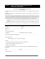
General advice on safety:
When handling the VF SERIES avoid hard shocks, jolts, impacts, etc.
Product liability and warranty:
The VF SERIES level gauge is designed solely for measuring the distance, level and volume of liquids,
solids and particulate materials.
Special codes and regulations apply to its use in hazardous areas.
Responsibility as to suitability and intended use of these level gauges rests solely with the user.
Improper installation and operation of our level gauges may lead to loss of warranty.
In addition, the "General conditions of sale", forming the basis of the purchasing contract, are applicable.
If you need to return the level gauge to the manufacturer or supplier, please refer to the information given
in Annex D.
Items supplied:
• Signal converter bolted to sensor.
Factory settings sheet for the signal converter.
Documentation supplied:
• Installation and operating instructions (this manual): detailed user manual and reference book,
including description of special versions and functions. This documentation is structured on lines
similar to those given in the DIN V 19259 Standard.
• Approval documents, unless reproduced in the installation and operating instructions.
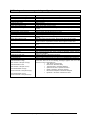
Software history
Introduction
Mth./Yr.
Signal converter
Hardware
Firmware
04/00
VF
SERIES
1.10
07/00
VF
SERIES
1.20
User program
Hardware
Operatingsystem
Software
Win 3.x
P.C.
Hycontrol VF SERIES Installation and operating instructions
Instructions
Device
User
program
v0.42a
Online help
v0.43a
Online help
Win 95 / 98 PC STAR 2
Page: 3
10/00
1. Range of application
The VF SERIES REFLEX level gauging system is designed to measure the distance, level and volume of
liquids, slurries, solids and particulate materials. It can be operated on storage, process tanks and also on
stilling wells.
Because of the low power output, the microwaves are not harmful to humans.
2. Mode of operation and system structure
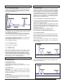
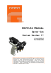
2.1 Measuring principle
(REFLEX TDR)
(TDR = Time Domain Reflectometry)
The
converter
electronics
sends
an
electromagnetic pulse to the probe system.
That electromagnetic pulse travels at the
speed of light down to the product surface.
Here the pulse gets partially reflected and
travels back to the converter electronics. The
distance between the converter flange and
product
surface
is
therefore
directly
proportional to time. For a distance of 1m, the
-9
pulse’s travel time is 6.7ns (6.7*10 seconds).
They are defined by two “plausibility” Windows,
one for the emitted pulse, and one for the
reflection.
radar
pulse
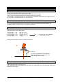
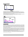
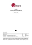
The polarity and the amplitude of the partially
reflected REFLEX pulse depends on the εr
(epsilon r) of the two mediums, which are
above and below the reflecting surface. Under
normal circumstances the medium above the
surface is a gas with an εr close to 1.0 and the
medium below is the process medium with an
higher εr. The figure on the right shows a
typical pulse reflection of such a standard
application. The advantage of the TDR
measuring principle is that the travel time of
the pulse and therefore the accuracy of the
level measurement, is completely independent
of the εr and the density of the process
medium.
One of the front-end electronic’s main tasks is
to sample the complete measurement signal at
the upper probe end. As the signal is too fast
to get sampled with a sufficient resolution in
time, the electronics sends continuous
electromagnetic pulses down the probe and
samples each signal a fraction of time later
than the previous signal (sampling). The so
generated audio signal is a direct copy of the
real time measuring signal with a 228 000
times slower time base.
measuring
windows
pulse
reflection
sampling
transformed signal
This means that 1m of distance between
converter flange and process surface is not
anymore equivalent to a time of 6.7ns but to a
time of 1.5ms. This time transformed audio
signal is now sufficiently slow and can be
directly processed. In order to save electrical
power, the converter samples the measuring
signal only in the relevant areas.
Hycontrol VF SERIES Installation and operating instructions
Page: 4
10/00
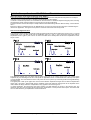
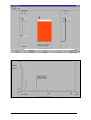
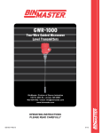
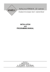
2.2 Signal processing (digital)
The figure below shows the digital signal processing of the VF SERIES. It can be split up into two main
blocks. The function of the first block with its pulse generator, sample circuit and digital PLL (Phase
Locked Loop) time base that was already referred to in the previous chapter. It is linked via the audio
signal to the second block that completes the signal processing of the electronics. An analogue to digital
converter samples the audio signal before the microprocessor processes the data with different filter
and measurement algorithms. In a final step the processor calculates the product level and sends this
information to the output circuit.
pulse
generator
sample
circuit
digital
time
base
&
window
management
micro
processor
output
circuit
current
loop
AD
converter
audio signal
digital time transformation
digital signal conversion
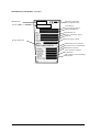
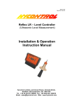
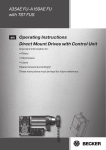
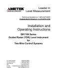
2.3 Modularity (signal converter, 1"G/NPT, probe system)
The measuring system consists of the sensor system and the signal converter.
The flange system is made up of the probe support, the sealing system with signal contact, and the
process connection.
The compact signal converter contains the TDR measuring circuit and the entire signal processing
system, including the provision of a standardised output signal (4 - 20 mA or digital interface).
The signal converter can be separated from the sensor system under process conditions, without
compromising tank integrity.
Converter
Flange or 1"G
connection with
pressure tight
signal feed
through
Probe
Hycontrol VF SERIES Installation and operating instructions
Page: 5
10/00
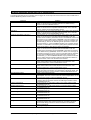
3. Input
3.1 Measured variable (distance, level, volume)
The primary measured variable is the distance between a reference point (as standard: tank mounting
flange) and a reflecting surface (surface of the liquid).
Level is calculated from the measured distance value, and the tank height.
Volume output is possible by entering a conversion table (max. 20 points).
The strength of the reflected signal can be measured for qualitative assessment of the tank product or
®
its surface. (Only available with HART communication).
3.2 Measuring range
[0.15 - 24 m (0.50 - 72 ft)]
Minimum tank height: 0.15 m (0.5 ft).
The useful range will depend on the sensor type, the reflection properties of the tank product, the
installation position, and the presence of interfering reflections.
3.3 Dead zone
The dead zone distance is the minimum measured distance between the mounting flange (reference
point) and surface of the tank product.
For twin cable εr>10
For twin cable εr<10
For mono cable εr<10
For mono cable εr>10
For coax system = 0
150 mm. (5.9 '' )
300 mm. (11.8 '' )
400 mm. (15.8 '' )
300 mm. (11.8 '' )
for all εr
These are min. values. Default
value 400mm. (15.8 '') .
Recommended minimum values: see following sketches.
Nozzle height
To set the right dead zone and detection
delay add the height of the nozzle to the
values mentioned in the table.
3.4 Out-of-range performance
When the level measuring range is exceeded (including flooding) the output value will stay at the
(adjustable) dead zone (see Sect. 8.5.3).
If the measured value drops below the level range, the output will stay at the set lower range limit
(distance = tank height).
Hycontrol VF SERIES Installation and operating instructions
Page: 6
10/00
4. Output
4.1 Variants
Variants
Remarks
Current output HART®
Ex-ia current output HART®
Passive ; HART® protocol
Intrinsically safe; Passive ; HART® protocol
Described
in Section
4.2
4.2
®
All versions with HART protocol can be operated with the PC-STAR 2 PC program (see Section 8.11).
Overview of digital communication possibilities:
VF SERIES
4 ... 20mA
+ HART
4mA
+ HART
Converter
HART
FE
I L D COMM UNI CAT I ONS PROT OCO L
F1
F2
F3
F4
HAR T C ommunic ator
I
>>
>>>>
>>>
O
ABC
DE F
7
J KL
8
P QR
5
3
>
.
F I EL D CO MMUN I CATI O NS PRO T OCOL
YZ /
2
<
HART
6
VW X
1
0
9
M NO
4
ST U
# %&
GHI
*
:+
_
F1
F2
F3
F4
HA RT Communicator
I
ABC
HARTHHC
>>
>>>>
>>
O
DE F
7
JKL
0
9
P QR
5
6
VW X
1
# %&
GHI
8
MN O
4
S TU
YZ /
2
<
3
>
.
*
: +
_
PC STAR 2
PC STAR
or
HART specific software
and operating devices
HARTHHC
Point-to-point
HART-Master
Multidrop
4.2 HART® communication
®
The HART communications protocol can, in accordance with the Rosemount Standards, be used with a VF
SERIES.
Electrical connection: see Section 7.6.
There are two ways of using the HART® communication:
a) As a point-to-point connection between the VF SERIES and the HART® Master equipment.
HART
4…20 mA
Hycontrol VF SERIES Installation and operating instructions
MASTER
Page: 7
10/00
l
b) As a multipoint connection (multidrop) with up to 5 devices (VF SERIES or other HART® equipment), in
parallel on a 2-wire bus:
Theoretically, we can plug up to 15 instruments. But in practice, we do only 5.
When configuring instruments in multidrop mode, all instruments must have previously been configured with
addresses different from each other (address must be other than ''0'' because ''0'' is an address solely used for
point-to-point mode (4-20 mA output valid.).
Before switching to multidrop mode, one has to make an address configuration for each instrument in point-topoint mode. On multidrop mode, only digital information is used (4-20 mA output been not valid in this case, the
current output of each instrument is set to 4 mA).
Step 1:
We fix the address of the device (different from ''0'').
HART
MASTER
Step 2:
®
Multidrop connection of 5 devices (VF SERIES or other HART equipment), in parallel or on a 2-wire bus:
Address:
1
2
3
4
4
4 mA
5
HART
MASTER
4
other
HART
device
4
other
HART
device
During start-up, on multidrop mode, it should be noticed that each instrument needs a current value of 22 mA (see section 5.7).
After this start-up, the instruments comes back to a fixed value of 4 mA in multidrop mode. After the instruments are powered
on(for instance : VF SERIES), the current output remains fixed to 22 mA during 15 seconds. Then, it changes to 4 mA.
If we look at the example of the start-up: assuming that we have connected 5 Instruments. That means that we need a current of
5 * 22 mA. That it to say 110 mA during 15 seconds.
Rc = 250 Ω
…
Vs (24 V)
S
…
HART
M AST ER
4 mA
(22 mA)
4 mA
(22 mA)
4 mA
(22 mA)
…
Taking account of the Resistor load (250Ω) and the constant power supply (24 V), we notice that the power supply is not
sufficient enough ( Voltage drop within the resistor 110 mA * 250Ω = 27.5 V!!). Hence, it appears that it is necessary to make
a short-circuit of the resistor of 250 Ω during start-up. That explain the use of S . With that design, we can grant good liability
of our instruments.
Hycontrol VF SERIES Installation and operating instructions
Page: 8
10/00
4.3 Service information
Service information can be called up via the following interfaces:
• Current output: 22 mA in case of error signal.
• Digital interfaces: interrogation of error flags
5. Measuring accuracy
5.1 Reference conditions
•
•
•
•
•
•
•
Temperature = +20°C (68 °F).
Pressure = 1013 mbar abs (14.5 psia.).
Air humidity = 65%.
Highly reflecting product (e.g. water) with calm surface.
Tank diameter > 1 m (3.28 ft).
Mounted at least 300 mm (12 '') away from tank wall.
Mounted flat on the tank (no nozzle).
5.2 Current output accuracy
The accuracy of the 4-20 mA output is 0.01% of measured value.
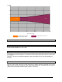
5.3 Error of measurement
Since the measuring process primarily determines distance, measuring accuracy can only be specified
as a function of the distance. For that reason, all figures given in this Section 5 refer to the measured
distance.
Hycontrol VF SERIES Installation and operating instructions
Page: 9
10/00
Accuracy
mm
30
20
10
0
± 5 mm
± 0,05 %
-10
-20
-30
5
10
15
20
24 m
Distance to flange
= coax, rod ( mono or twin)
or cable ( mono or twin)
= only cable ( mono or twin )
5.4 Repeatability
Repeatability is equal to half the value of the error of measurement.
5.5 Measured value resolution
Measured value resolution is: 1 mm / 0.04".
5.6 Transient recovery time
The transient recovery time is determined by the setting parameter "time constant" (1 ... 100 s).
The transient recovery time relative to 1% deviation from the steady-state value is approx. 4.6 times the
time constant.
However, in the case of unusual rapid changes in level, the transient recovery time may deviate from
this figure.
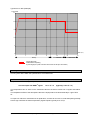
5.7 Turn-on characteristics/turn-on drift
After the VF SERIES has been switched on, the current output is fixed to 22 mA during 15 seconds.
Next, the current output is driven to probe length until a product reflection is detected. The current
output will then rise to the measured value. Full measuring accuracy is obtained after 23 seconds
operating time with default parameters (time constant = 5 seconds).
Hycontrol VF SERIES Installation and operating instructions
Page: 10
10/00
Typical turn-on drift (example):
Current (mA)
25
20
15
10
5
Time (sec)
0
0
5
10
15
20
25
Research
Startup
30
Measurment
Current output value
Variable duration depending
on probe length (for a probe of 24 meters the research can take up to 40 secondes)
5.8 Long-term drift
The long-term drift is within the specified error of measurement.
5.9 Effect of ambient temperature
Temperature coefficient, signal output:
®
Current output with HART signal:
< 0.01 % / °K
(typically: 0.003 % / °K)
The temperature has no effect on the measured value as the device carries out a regular self-calibration.
The temperature effect of the atmosphere above the liquid product results theoretically in 1ppm/°K for
air.
In respect of reference measurements in liquid tanks, it needs to be borne in mind that liquids generally
have a high coefficient of thermal expansion (organic liquids: typically 0.15 %/°K)!
Hycontrol VF SERIES Installation and operating instructions
Page: 11
10/00
6. Operating conditions
6.1
Installation conditions
Refer to Section 7.4 for selection of the optimal sensor type
6.1.1 First mounting of device
Before installing the device, please refer to the following guidelines:
100 mm.(3.9 '') MIN
Twin rod cable
0 mm. (0 '') MIN
Coax cable
300 mm.(11.8 '') MIN
Mono rod cable
6.1.1.1 Excessive bending of the cable
BE CAREFULL DON'T BEND
CABLES TOO MUCH
Hycontrol VF SERIES Installation and operating instructions
Page: 12
10/00
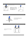
6.1.1.2 No penetrating nozzle
Penetrating nozzle is forbiden
Ideally the VF series
mounted without a nozzle
directly mounted in a
welding socket, this gives
best measuring results at
lowest installation cost.
is
and
1"G
the
the
6.1.1.3 Mounting on a nozzle
Avoid nozzle size higher than 150 mm
(5.9 ''), especially when B < 80mm (3.1'').
A
Generally respect B>A.
B
6.1.1.4 Interference between two VF SERIES
There must be 2 meters mini. between
two VF series if we want no
interference.
Hycontrol VF SERIES Installation and operating instructions
2 m mini.
Page: 13
10/00
6.1.1.5 Mounting inside side mounted vessel or stilling well
Here we have an optimal mounting inside
vessel or stilling well. Take care of fixing
or centering the probe end to prevent this
one from touching the vessel wall. In case
of the rod or cable type process, "T" probe
end for rods or large dimensions height
are advised.
6.1.1.6 Preferential mounting in agitated tank.
FILLING
AGITATOR
FIXING AT THE BOTTOM
6.1.1.7 Shortening of probe
Screw A4 70 HC , M6-10 DIN 913
Loosen the screws take out the cable
shorten the length of the cable and
enter the cable in the weight and
tighten the screws. Reduce probe
length in the parameter setting of the
device.
* only for liquid applications
Hycontrol VF SERIES Installation and operating instructions
Page: 14
10/00
6.1.1.9 Sunshade
In case of direct exposure to sunshine a sunshade is recommended.
6.2 Ambient conditions
6.2.1 Hazardous locations
Approvals:
1G EEx ia IIC T6…T3
1G EEx ia IIB T6…T3
1/2 D T 100°C EEx ia
6.2.2 Ambient temperature of signal converter and process temperature
For the VF SERIES the max. and min temperature of the converter and the flange are linked.
Minimum converter temperature-30°C (-22 °F)
Minimum product temperature -50°C (-58 °F)
Maximum converter temperature+55°C (+131 °F)
Maximum flange temperature +90°C(+195°F)
6.2.3 Storage temperature
-40 °C ≤ T ≤ 80 °C
/
-22 °F ≤ T ≤ 195 °F
6.2.4 Environmental class
Installation in free air level DI according EN60654-1
6.2.5 Protection category
IP65
6.2.6 Shock resistance
Resist to shocks according EN61010 §8.2 0.5 J
6.2.7 Vibration endurance limit
IEC 68-2-6 and pr EN50178 (10-57 Hz: 0.075 mm/57-150 Hz: 1G)
6.2.8 EMC ( Electromagnetic Compatibility)
The devices satisfy the requirements of EN 50081-1, EN 50082-2
Hycontrol VF SERIES Installation and operating instructions
Page: 15
10/00
6.3 Product conditions
6.3.1 Physical properties of the products
Physical properties (such as density, viscosity, conductivity, relative permitivity, magnetic properties,
etc.) have no effect on measurement results.
The relative permitivity is merely required to have a minimum value in order to ensure reliable
measurements (see Section 6.3.2).
6.3.2 Relative permitivity
The (relative) permitivity of the product (εr, Epsilon-R) determines the strength of the reflected signal.
Measurement results are not affected so long as the reflected signal is strong enough. Reliability and
the maximum measuring range are dependent upon the relative permitivity.
The minimum permitivity depends on the type of probe being used, recommendation:
Mono > 2.3
Twin > 1.8
Coax > 1.5
6.3.3 Product limitations
TDR-based level measuring devices are not suitable for products with severe deposit characteristics.
This, with the limitation mentioned in §6.3.2, are the only limitations of the device.
6.3.4 Maximum allowable operating pressure (max. 40 bar)
The maximum allowable operating pressure for the standard version is 16 bar / 58 psig.
Option: 40 bar./ 580 psig
6.3.5 Maintenance
Maintenance is not necessary in standard applications, however when the sensor is heavily
contaminated, this can lead to measurement errors.
Hycontrol VF SERIES Installation and operating instructions
Page: 16
10/00
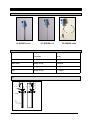
7. Design
7.1 Models
VF SERIES coax
VF SERIES rod
VF SERIES cable
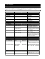
7.2 Dimensions, weights
SENSOR TYPE
Weight converter +
Extra Weight
1 m probe
Per m.
Mono-rod
≅ 2 kg / 4.4 lb
1.24 kg/m
Mono-cable
≅ 2 kg / 4.4 lb
0.14 kg/m
Twin-cable
≅ 2 kg /4.4 lb
0.28 kg/m
Coax
≅ 3 kg / 6.6 lb
≅ 1.1 kg/m
Coax
70
134
205
Connector
83
L
FLANGE
Tube:
ø28 (316L)
ø26.7 (ALLOY C276)
Hycontrol VF SERIES Installation and operating instructions
Page: 17
10/00
Twin rod
83
70
83
205
134
70
Connector
134
Mono rod
ø102
L
L
L
Flange
Diam. 8
mono cable
70
134
83
Cable ø4 FEP coated
100
Cable ø4 for powders
205
Connector:
Diam.102
M8
Diam.25
Twin cable
134
83
205
70
Connector
Diam.102
L
Flange
Weight
60
Cable
M8
Hycontrol VF SERIES Installation and operating instructions
Page: 18
10/00
7.3 Replacement of the signal converter
Always disconnect power before assembling the signal converter.
Hazardous-duty systems
Before replacing the signal converter (instrument "head") in a hazardous location, make absolutely
certain that there is no explosion hazard (gas-free certificate).
1. Disconnect all cables from the instrument. See Section 7.6.
2. Remove the 4 Allen screws M (Allen key size 4 mm / 0.16'') and lift off the signal converter. The
flange system will remain sealed.
DANGER!
On pressurised tanks, do not in any case remove the 4 screws H connecting the VF SERIES flanges
with the tank!
3. Install the new VF SERIES signal converter (take care of the signal contact tip).
4. Screw the 4 Allen screws M (Allen key size 4 mm / 0.16'').
6. Check power voltage.
7. Reconnect all cables in the terminal compartment as described in Sect. 7.6.
Important:
Ensure that the ‘O’ sealing of the signal converter is well greased.
Hycontrol VF SERIES Installation and operating instructions
Page: 19
10/00
.4 Selection of sensor type
Probe selection guide
MONO ROD
COAX
TWIN CABLES
MONO CABLE
Recommended when
For liquid, powder or
granules level
Only for clean liquids
level
For high silos or tanks with
liquids or granules
For all fine powder
applications
< 6 m – small distance
1.
2.
3.
4.
5.
6.
To be used complemen- 1. Connection size is <
tary to coaxial for all
DN80 mm (3").
others applications.
2. Liquid agitated, acting
For contactless measulike stillwell.
rement
through
the 3. Liquid or vapours spray
plastic wall of tanks or in
near the probe.
a sheath plastic tube for
4. High flow inside vessel
high corrosive fluids or
For example:
crystallisation problems
oil/water separators.
(high dielectric).
5. Can be heat traced.
For exotic application 6. Contact with metallic
material as tantalum.
part or tank wall possible.
7.High magnetic field in
For specific probe shape
tank.
with angles.
For minimum bottom 8. CE approval in plastic
tanks.
dead zone in small
tanks.
9. Very low ε r liquids.
For
full
level
10. Foam applications.
measurement.
1. Same as rods, but up to
1. For all fine powder applica24 meters and over 6 metions > 6 metres.
ters.
2. For all very viscous liquids
2. For smaller tanks with no
like liquid sugar.
clearance for rigid probes
3. For building a coaxial
(coax or rod).
version
3. For side installations with
with an existing stillwell
allowed probe max. 6m/20ft
(Calibration required).
on liquids only.
4. Very corrosive liquids with
FEP coating.
5. Crystallising acids with
FEP coating.
Avoid when
1.
2.
Contact inside the tank
Temperature > 240°C
1. Crystallising liquids.
2. High deposal product
application.
3. Powders.
1. Small connection flange
with nozzle.
2. Agitated tank without
anchoring.
1. Long and small diameter
nozzle installation - min recommended flange 4” or
mounted with 2” flange.
1. Max nozzle height base
on its diameter, calculation is:
h = (Lxd) + 140mm
4xa
L = Probe length (mm)
d = Nozzle diameter
(mm)
a = Flange eccentricity
from tank center (mm)
Main Applications are
1.
2.
3.
4.
5.
6.
Tanks < 6 meters
> 6 meters under request
Viscous fluid for very
high viscosity use single
probe
All application, NH3,
solvents, oil, LPG, etc.
For OEM integration,
molded in plastic liner or
welded in the tank
For multifluids storage
tank
1. Tanks < 6 meters.
2. LPG, LNG, Solvent,
NH3, Fuel oil, Foam,
Alcohol, Displacer, open
channel measurement
replacement, threat connection installation...
Hycontrol VF SERIES Installation and operating instructions
1. Tank farm.
2. LPG, LNG, NH3.
spheres, beer, alcohol.
1. Cement, limestone, flyash,
alumna, etc...
2. Acids.
3. Liquid sugar, honey,
sirops.
4. For very high temperature
with single cable construction.
Page: 20
10/00
7.5 Materials of construction
Check that the materials of the sensor, extension, flange, gaskets (Viton/Kalrez), and PTFE (contained
in all versions) are compatible with the product!
7.5.1 Signal converter
Housing: Aluminium with epoxy or powder coating.
7.5.2 Flange system
1" G Standard; all other flanges on request.
7.5.3 Materials in contact with the product.
*Stainless steel 316 for the cable, Hastelloy optional.
*Stainless steel 316 L standard for all the process connections, others on request.
*PTFE.
*Viton O-Ring, Kalrez optional.
7.6 Electrical connection
The electrical connection for the power supply is made in the terminal compartment of the signal
converter. Observe requirements specified in VDE 165.
In case of installation in hazardous areas, only certified intrinsically safe equipment may be connected
to the VF SERIES.
Two kinds of electrical connection are available:
1. DIN Connector:
Terminals:
3 poles + ground. Wire cross-section max 1.5 mm ≈ (AWG 16).
Ex-equipotential bonding:
U-clamp terminal (max. 4 mm conductor cross-section) at neck of
signal converter.
Cable entries:
M25x1.5 (PG11). Standard cable gland: cable clamping area = 8-10
mm).IP65
Signal cable shielding:
No shielding needed.
2
2
Power supply:
1. Remove the screw P and lift off the connector from the signal converter.
2. Put a screwdriver in F and separate N from R.
3. Connect the current loop to terminal 1 and 2 (there’s no polarity to respect). Use ferrules to protect
cable ends. The terminal 3 and E remain non-connected.
4. Re-assemble N and R.
5. Put the seal in place, connect R to the signal converter tighten and screw P.
The terminal E is not connected with the signal connector housing or with the flange system of the
instrument.
For standard and Ex applications only the intrinsically safe 2-wire loop must be connected to the
terminals 1 and 2. The terminal E as well as terminal 3 remains non-connected.
Hycontrol VF SERIES Installation and operating instructions
Page: 21
10/00
2
3
3
1
2
1
2. ISO16:
2
Terminals:
Ex equipotential bonding:
Wire cross-section max 1.5 mm
=(AWG 16)
2
U-clamp terminal (max. 4 mm ≈ conductor cross-section) at neck of
signal converter.
Cable entries:
M16x1.5. With standard cable gland: cable clamping area = 8 -10 mm).
IP65
Signal cable :
No shielding needed.
Power supply:
1. Remove the 4 screws T and open the terminal compartment.
2. Connect the current loop to the terminal U (there’s no polarity to respect). Use ferrules to protect
cable ends.
3. Close the terminal compartment.
The terminal E is not connected with the signal connector housing or with the flange system of the
instrument.
For standard and Ex applications only the intrinsically safe 2-wire loop must be connected to the
terminals 1 and 2. The terminal E remains non-connected.
Hycontrol VF SERIES Installation and operating instructions
Page: 22
10/00
8. User interface
8.1 HART® Communicator
No local display is available for the installation and configuration of the VF SERIES. Configuration can be
®
carried out with a HART communicator or the PC-STAR 2 program.
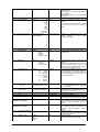
8.2 Description of functions via HART® Communicator HC 275 (Version 1.00)
Function (Fct.)
1.0
1.1.0
1.1.1
1.1.2
1.1.3
Enter range
Default value
PROCESS VAR.
MEASUREMENTS
LEVEL
DISTANCE
VOLUME
Level value.
Distance value.
Volume value if a strapping table is
programmed.
Ullage Volume value if a strapping table is
programmed.
1.1.4 ULLAGE VOLUME
1.2.0 Inputs/ Outputs
1.2.1 FUNCTION I
1.2.2 I
1.2.3 %
2.0 CONFIG./TEST
2.1.0 OPERATION
2.1.1.0 BASIS PARAMETER
2.1.1.1 TANK HEIGHT
Function associated to the current output
(Primary Variable).
Current output value (mA)
Percentage of PV range.
Min value : Probe Length
Max value : 60000 mm
6000 mm /2362 ''
2.1.1.2
PROBE LENGTH
Min value : 0 mm
Max value : Tank height
and < 27000 mm
6000 mm / 2362''
2.1.1.3
TIME CONSTANT
Min value : 1 second
Max value : 100 seconds
5 seconds
2.1.1.4
DEAD ZONE
Min value : 0 mm
Max value : Probe length
400 mm / 15.8 ''
2.1.1.5 Sensor info
2.1.1.5.1 Sensor upper limit
2.1.1.5.2 Sensor lower limit
2.1.1.5.3 Sensor min. span
2.1.2.0 DISPLAY
2.1.2.1 LENGTH
2.1.2.1.1 LENGTH UNIT
Tank height.
The tank height is defined as the
distance between the bottom of the
tank and the lower flange surface.
This value has to be equal to the exact
length of the probe. The only situations for
changing this value is if the probe length
has been changed.
The time constant allows to filter possible
signal fluctuations when the product
surface is turbulent.
Measurements near the flange may not be
precise or reliable. Therefore, the Dead
Zone prevents measurements in this area.
Measurement may not be precise in an
area less than this recommended value,
depending on the probe type.
Read only Menu. Upper sensor limit.
Read only Menu. Lower sensor limit.
Read only Menu. Sensor minimum span.
m
cm
mm
inch
Ft
Optional Unit
Options (number of
decimal places)
0
1
2
3
4
5
6
millimeter [mm]
2.1.2.1.3.0
DEFINE
NEW UNIT
2.1.2.1.3.1 UNIT NAME
4 ASCII characters
“unit”
2.1.2.1.3.2 UNIT FACTOR
Min value : > 0.0
1.0
2.1.2.1.2 DISPLAY FORMAT
Description
Options
2 decimal places
Hycontrol VF SERIES Installation and operating instructions
Length unit of displayed value (level / distance).
The optional unit allows the user to define
a new unit (name and factor) see menu
2.1.2.1.3
Defines the displayed length values format
(option of the HART® communicator
H275).
Optional unit name. User has to enter the
unit name before using it in the menu
“LENGTH UNIT”.
Optional unit factor. User has to enter the
Page: 23
10/00
2.1.2.2.0 VOLUME
2.1.2.2.1 VOLUME UNIT
2.1.2.2.2 DISPLAY FORMAT
2.1.3.0
2.1.3.1
ANALOG OUTPUT
FUNCTION I
Max value : 100000
Unit Factor before using it in the menu
“LENGTH UNIT”.
With a factor 1.0, the unit is equivalent to
one millimeter.
With a factor 1000.0, the unit is equivalent
to one meter.
Options
Unit for
table").
m3 Liter [l]
l
US Gal
Ft3
bbl
M3/h
Ft3/h
kg
Metric Tons
US Tons
Options (number of
2 decimal places
decimal places)
0
1
2
3
4
5
6
Options
RANGE I
Options
ERROR DELAY
Options
delay
seconds
seconds
seconds
minute
minutes
minutes
minutes
SCALE I
min. 4 mA
Min value : 0
Max value : Scale I max
0
2.1.3.5
SCALE I
max. 20 mA
Min value : Scale I min
Max value : Tank Height
6000 mm / 236 ''
2.1.4.0
2.1.4.1
2.1.4.2
USER DATA
TAG
SERIAL NUMBER
VF SERIES 00
2.1.4.3 FRENCH
COMMISSION NUMBER
2.1.4.4 GERMAN
COMMISSION NUMBER
RELEASE NUMBER
2.1.4.5
PROBE TYPE
Options :
Rod
Twin Rod
Cable
Defines the displayed
format.
(Option
of
communicator H275).
volume value
the
HART®
Current output range. 4 to 20 mA (1st
choice).
When the VF SERIES is in error mode, the
current output is frozen except if the
second choice is selected and then the
current output is fixed at 22 mA.
This menu is available in case the range I
menu is set to 4-20 mA with error 22 mA.
This parameter sets the delay before the
current output goes to 22 mA after the
error mode occurred.
2.1.3.4
2.1.4.5
The selected unit is only used to display
the conversion value from the strapping
table.
4-20 mA
No delay
No
10
20
30
1
2
5
15
("volume
Current output function (measured value to
be displayed).
4-20 mA
4-20 mA +
22 mA if Error
2.1.3.3
values
Level
Level
Distance
Volume
Ullage Volume
2.1.3.2
conversion
Rod
Hycontrol VF SERIES Installation and operating instructions
Input the lower range value (corresponding
to 4 mA) depending of the parameter
2.1.3.1 choosen.
Input
the
upper
range
value
(corresponding to 24 mA) depending of the
parameter 2.1.3.1 choosen.
Tag number of device.
Read only menu.
Each device has its proper serial number.
Read only menu.
This number is factory set. Refer to this
number in case of warranty or service
claims.
Read only menu.
This number is factory set. Refer to this
number in case of warranty or service
claims.
Read only menu.
Release number of the device (Software
and Hardware version).
Read only menu.
Probe type attached to the flange.
Page: 24
10/00
Cable +counterweight
Twin Cable
Twin Cable +
counterweight
Coax
Special 1
Special 2
Special 3
2.1.4.5
CHECKSUM
Read Only menu.
Similar to the release number. This
parameter allows to identify the software
version of device.
2.1.5.0
APPLICATION
2.1.5.1.0 THRESHOLD
2.1.5.1.1 LEV. PULSE AMP.
2.1.5.1.2 LEV. PULSE GAIN
2.1.5.1.3 THRESHOLD
2.1.5.2
DISTANCE INPUT
2.1.5.3
DETECTION DELAY
2.1.5.4
2.1.5.5
2.1.6.0
2.1.6.1
SEARCH PROBE
END
RESET VF SERIES
SERIAL I/O
ADDRESS
2.1.7.0
2.1.7.1
STRAP TABLE
VOLUME UNIT
2.1.7.2
INPUT TABLE
2.1.7.3
DELETE TABLE
2.2.0 TESTS
2.2.1 TEST OUTPUT
200 mV;
amplification
factor: 3 at 1
meter.
Read only value.
Dynamic value.
Amplitude of level pulse in millivolts.
Read only value.
Dynamic value.
Amplification of level pulse (gain 0,1,2, or
3)
Threshold of the level pulse (in millivolts).
The threshold évolutes in terms of gain
amplification factor changing by the
electronic converter.
This function allows forcing the VF
SERIES to search for the product surface
in a particular zone other than the actual
measuring zone. If there is no level signal,
you can enter an estimated value.
This function forces the instrument not to
analyse reflections in a zone directly below
the flange. The entered value of the
detection delay must be smaller than the
"dead zone" value.
Measures automatically the probe length.
Restarts the VF SERIES.
Options
Address from 0 to 15
0
Options
Sets the address of the device when this
latter is connected on a HART Multidrop
networks. The current output drifts to 4
mA.
m3 Liter [l]
l
US Gal
Ft3
bbl
M3/h
Ft3/h
kg
Metric Tons
US Tons
Options :
0 point (No volume
Contains from 0 to 20
table)
points.
Unit for
table").
Options :
4 mA
12mA
20 mA
Other
This function allows the current output to
be tested.
The output can be set to one of the listed
values. With a reference ammeter, the
calibration of the current output can be
verified.
conversion
values
The selected unit is used to define the
strapping table values. .
This function defines the strapping table.
The maximum number of points is 20. The
4 mA current output in volume is the first
value in the table. Each subsequent value
must be greater than the previous one.
The length and volume units can be
changed later without affecting the settings
in the table. Calculations are done
automatically in the instrument.
This function deletes the strapping table.
2.3.0 SERVICE
2.3.1.0 BASIS
Hycontrol VF SERIES Installation and operating instructions
("volume
Page: 25
10/00
PARAMETERS
2.3.1.1 OFFSET OF
MEASURE
263 mm / 10.4 ''
Correction for time the pulse takes to
travel from the elec-tronics to the flange.
2.3.1.2
Min value : 0
Max value : 24000 mm/
1448 ''
PROBE TYPE
Options :
Rod
Twin Rod
Cable
Cable + counterweight
Twin Cable
Twin Cable +
counterweight
Coax
Special 1
Special 2
Special 3
APPLICATION TYPE Options :
1 Product, 1 Level
2 Products , 1 Level
Rod
Your VF SERIES has been ordered with
one of these probe types. This probe type
can be changed only in the service menu.
1 Product, 1 Level
2.3.1.4
EPSILON R
1.0
Process configuration (1 or 2 liquids).
Note: for the specification of 2 liquids, the
top liquid must have an εr < 5, and be
always at the flange.
This menu is available if "application type"
is "2 products, 1 Level".
Enter the Epsilon R value of the product
above the surface to be measured. This
menu is not valid for the "reverse probe
type".
2.3.2.0
2.3.2.1
APPLICATION
VOLTAGES VALUES
2.3.2.2
WATCH PULSES
2.3.2.3
MEAS. STAT. HIST.
2.3.2.4
PROBLEM HISTORY
2.3.3.0
2.3.3.1
CALIBRATION
CURRENT OUTPUT
2.3.3.2
ELEC. CALSPEED
Min value : 0.7
Max value : 3.0
1.5189
2.3.3.3
MECH. CALSPEED
Min value : 0.7
Max value : 9.999
1.0
Min value : -250 mV
Max value : +250 mV
0 mV
Min value : 0
128
2.3.1.3
2.3.3.4 ELECTRONIC
OFFSET
Min value : 0.8
Max value : 99.0
This function displays the voltage values
within the device :
Power supply (+/- 3 Volts)
Time base supply (VCO)
This function displays information about
each pulse (Reference pulse, flange pulse
and level pulse). For each pulse there are
set values. For example window number,
pulse amplitude, position of the pulse
inside the window etc.
This function indicates the 24 last process
status.
Markers :
. Level Normal
. Full Tank
. Empty Tank
. Level Lost
This function indicates the last 24 device
errors.
This function allows to calibrate the current
output. Factory set.
2.3.3.5 AUTO OFFSET
MEASURE
2.3.3.6
SET REF.
Hycontrol VF SERIES Installation and operating instructions
Electronics speed constant. Not necessary
to change in any circumstance. This is
factory set and is specific to each
electronics. It is always necessary to
record this before an EEPROM 'Factory'
reset, so that it can be re-entered.
Mechanical speed constant. This is the
correction factor relating to the actual
probe type and the pulse propagation
speed. This is factory calibrated, and
needs to be recalibrated only if the probe
is changed or extended.
Electronic offset. Signal offset.
This parameter Sets the offset value of the
audio signal. This parameter alllows to
adjust the level of signal amplitude to
mask non-valid pulses. VF SERIES uses
this value to control electrically the level of
signal amplitude: The higher this value is,
the higher the non-valid signal amplitude
is.
This function calculates automatically the
offset (Parameter 2.3.1.1). After having
used this function, a manual calibration is
possible.
This parameter sets a value for the digital /
Page: 26
10/00
FREQUENCY
2.3.4.0
2.3.4.1
EEPROM RESET
USER RESET
2.3.4.2
FACTORY RESET
Max value : 255
analogue
converter.
Calibration
of
reference frequency is done only during
manufacturing (factory set).
This function allows a reset of the user
parameters to their default values. This
can be used in case the service engineer
wants to reprogram the default parameter
settings. A forgotten password can be
disabled by this method.
Note: Before using this function, contact a
HYCONTROL Service Department. This
function resets all the factory parameters.
It is essential to record the Offset of
measure, the electronic offset, Electronics
Speed Calibration and Mechanical Speed
Calibration
values
and
reference
frequency value before this function is
activated. These values can be then reentered after the reset. After a reset, the
current output must be calibrated again.
French and German command numbers.
2.3.4.3 IDENTIFICATION
3.0 ACCESS RIGHTS
3.1 MAINTENANCE PSW
Disables the access lock on the
configuration menu.
The password must contain exactly 9
characters.
E, R or U are used only. The password is
displayed in a scrambled format. It allows
HYCONTROL to decode the password in
case it was forgotten.
Specialist
access to the Service
Parameters.
3.2
SPECIALIST PSW
4.0
WATCH STATUS
5.0
5.1
5.2
5.3
HART® VARIABLES
MANUFACTURER
MODEL
FLD DEV REV
HYCONTROL
VF SERIES
1.0
5.4
SOFTWARE REV
1.0
5.5
HARDWARE REV
1.0
5.6
DEVICE ID
5.7
5.8
5.9
5.10
MESSAGE
DESCRIPTOR
DATE
NUM RESP PREAM
This function allows displays the status of
the device.
5.11 TAG
5.12 POLL ADDRESS
Hycontrol VF SERIES Installation and operating instructions
Read only menu.
Read only menu.
Field device revision.
Read only menu.
Software revision.
Read only menu.
Hardware revision.
Read only menu.
Read only menu. The device ID is also the
serial number of the device.
32 bytes of ASCII characters.
16 bytes of ASCII characters.
Month Day Year (xx / xx / xx).
Number of preamble in the response
frame of the device.
Tag name of the VF SERIES.
Address of the device.
Page: 27
10/00
8.3 Table of settable functions of PC STAR 2 (Version 1.00)
Function (Fct.)
Enter range
Default value
Description
Min value : Probe Length
Max value : 60000 mm/
2362 ''
6000 mm / 236 ''
1.1.2 DEAD ZONE
Min value : 0 mm / 0 ''
Max value : Probe length
400 mm / 15.8 ''
1.1.3 TIME CONSTANT
Min value : 1 second
Max value : 100 seconds
5 seconds
1.1.6 PROBE LENGTH
Min value : 0 mm / 0 ''
6000 mm / 236 ''
Max value : Tank height
and < 27000 mm / 1063 ''
Tank height.
The tank height is defined as the
distance between the bottom of the
tank and lower flange surface.
Measurements near the flange may not be
precise or reliable. Therefore, the Dead
Zone prevents measurements in this area.
Measurement may not be precise in an
area less than this recommended value.
The time constant allows to filter possible
signal fluctuations when the product
surface is turbulent. The minimum and
maximum values are 1 and 100 seconds
respectively. The factory default value is 5
seconds.
This value has to be equal to the exact
length of the probe. The only situation for
changing this value is if the probe length
has been changed.
1.0.0 OPERATION
1.1.0 BASIS PARAMETER
1.1.1 TANK HEIGHT
1.2.0 DISPLAY
1.2.4 LENGTH UNIT
1.2.5 VOLUME UNIT
1.2.6 DEFINE NEW UNIT
1.2.6.1 UNIT NAME
1.2.6.2 UNIT FACTOR
1.3 ANALOG OUTPUT
1.3.1 FUNCTION I
Options
Options
m
cm
mm
inch
Ft
Optional Unit
mm (Millimeter)
m3 Liter [l]
l
US Gal
Ft3
bbl
M3/h
Ft3/h
kg
Metric Tons
US Tons
4 ASCII characters
“unit”
Min value : > 0.0
Max value : 100000
1.0
Options
Level
Level
Distance
Volume
Ullage Volume
1.3.2 RANGE I
1.3.3 SCALE I min
1.3.4 SCALE I max
(20 mA)
1.3.5 ERROR DELAY
Length unit of displayed value (level /
distance).
The selected unit is only valid for the
length values. The optional unit allows the
user to define a new unit (name and
factor) see menu 2.1.2.1.3
Unit for conversion values ("volume
table").
The selected unit is only used to display
the conversion value.
Optional unit name. User has to enter the
unit name before to use it in the menu
“LENGTH UNIT”.
Optional unit factor. User has to enter the
Unit Factor before using it in the menu
“LENGTH UNIT”.
With a factor 1.0, the unit is equivalent to
one millimeter.
With a factor 1000.0, the unit is equivalent
to one meter.
Current output function (measured value to
be displayed).
Current output range. 4 to 20 mA (1st
choice).
When the VF SERIES is in error mode, the
current output is frozen except if the
+ 22 mA if Error
second choice is selected and then the
current output is fixed at 22 mA.
Min value : 0
0
Sets the lower range value for the current
Max value : Scale I max
output (4 mA).
Min value : 0
6000 mm / 236. 2 '' Sets the full-scale range for the current
Max value : tank Height
output (20 mA).
Options
No delay
This function is available in case the range
No delay
I menu is set to 4-20 mA with error 22 mA.
10 seconds
This parameter sets the delay before the
20 seconds
current output goes to 22 mA after the
Options
4-20 mA
4-20 mA
4-20 mA
Hycontrol VF SERIES Installation and operating instructions
Page: 28
10/00
error mode occurred.
30 seconds
1 minute
2 minutes
5 minutes
15 minutes
1.4.0 USER DATA
1.4.4 TAG
1.4.5 SERIAL NUMBER
VF SERIES 00
1.4.6 FRENCH COMMISSION
NUMBER
1.4.7 GERMAN COMMISSION
NUMBER
1.4.8 OPTION
1.4.9 PROBE TYPE
1.5.0 APPLICATION
1.5.1 DETECTION DELAY
1.6.0 SERIAL I/O
1.6.2 POLL ADDRESS
1.7.0 STRAP TABLE
1.7.2 INPUT TABLE
DYNAMIC CONFIGURATION
THRESHOLD
LEVEL PULSE GAIN
Options :
Rod
Twin Rod
Cable
Cable +counterweight
Twin Cable
Twin Cable +
counterweight
Coax
Special 1
Special 2
Special 3
Rod
Min value: 0 mm
Max value: dead zone
0
This function forces the instrument not to
analyse reflections in a zone directly below
the flange. The entered value of the
detection delay must be smaller than the
"dead zone" value.
Options
Address from 0 to 15
0
Sets the device address of each
instrument on HART Multidrop mode. In
this mode the current output is fixed to 4
mA.
Options :
Contains from 0 to 20
points.
0 point (No volume
table)
This function defines the strapping table.
The maximum number of points is 20. The
4 mA current output in volume is the first
value in the table. Each subsequent value
must be greater than the previous one.
The length and volume units can be
changed later without affecting the settings
in the table. Calculations are done
automatically in the instrument.
F11
LEVEL PULSE AMP.
LEVEL PULSE DISTANCE
DISPLAY AND SET
THRESHOLD VALUE
Affects the tag name to the device.
Read only menu.
Unique serial number of the device ID.
Each device has therefore its individual
address (HART® protocol).
Read only menu.
This number is factory set. Refer to this
number in case of warranty or service
claims.
Read only menu.
This number is factory set. Refer to this
number in case of warranty or service
claims.
Up to 15 bytes of ASCII characters
permitted.
Read only menu.
Release number of the device (Software
and Hardware version). Probe type
attached to the flange.
200 mV;
amplification
factor: 3 at 1
meter.
DISTANCE INPUT
Hycontrol VF SERIES Installation and operating instructions
Read only value.
Dynamic value.
Amplification of level pulse (gain 0,1,2, or
3)
Read only value.
Dynamic value.
Amplitude of level pulse in millivolts.
Read only value.
Dynamic value.
Distance of the level pulse.
Threshold of the level pulse (in millivolts).
The threshold is always displayed in terms
of the same gain amplification factor as the
product pulse.
The function forces the VF SERIES to
search for the product surface in a
Page: 29
10/00
SEARCH PROBE END
ADD POINT TO VOLUME
TABLE
DELETE POINT OF THE
VOLUME TABLE
TEST CURRENT OUTPUT
RESET VF SERIES
SERVICE
1.1 BASIS PARAMETERS
1.1.1 PROBE TYPE
1.1.2 OFFSET OF MEASURE
1.1.3 APPLICATION TYPE
1.1.4 EPSILON R
2.0
2.1
CALIBRATION
ELECTRONIC OFFSET
2.4
ELEC. CALSPEED
Options :
Contains from 0 to 20
points.
0 point (No volume
table)
Options :
4 mA
8 mA
12 mA
16 mA
20 mA
22 mA
Key : CTRL + ALT + R
particular zone. Therefore, if there is no
level signal, you can enter an estimated
value. If you are sure of what your
indication should be, and there is still no
reading, contact HYCONTROL about
decreasing the "Level Threshold" value.
CAUTION: Use of this function is not
recommended, except for trained
HYCONTROL service representatives.
Allows to calculate automatically the probe
length
This function defines the strapping table.
The maximum number of points is 20. The
4 mA current output in volume is the first
value in the table. Each subsequent value
must be greater than the previous one.
The length and volume units can be
changed later without affecting the settings
in the table. Calculations are done
automatically in the instrument.
This function deletes the strapping table.
This function allows the current output to
be tested.
The output can be set to one of the listed
values. With a reference ammeter, the
calibration of the current output can be
verified.
Restarts the VF SERIES.
Options :
Rod
Twin Rod
Cable
Cable + counterweight
Twin Cable
Twin Cable +
counterweight
Coax
Special 1
Special 2
Special 3
Rod
Probe type specification as mounted to the
flange, per the purchase order.
Min value : 0
Max value : 24000 mm /
944.9 ''
Options :
1 Product, 1 Level
2 Products , 1 Level
263 mm / 10.35 ''
Correction for time the pulse takes to
travel from the electronics to the flange.
1 Product, 1 Level
Min value : 0.8
Max value : 99.0
1.0
Process configuration (1 or 2 liquids).
Note: for the specification of 2 liquids, the
top liquid must have an εr < 5, and be
always at the flange.
This menu is available if "application type"
is "2 products, 1 Level".
Enter the Epsilon R value of the products
above the surface to be measured. This
menu is not valid for the "reverse probe
type" , (probe type 5).
Min value : -250mV
Max value : +250mV
0 mV
Min value : 0.7
Max value : 3.0
1.5189
Hycontrol VF SERIES Installation and operating instructions
Sets the offset value of the audio signal.
Allows to hide non-valid pulses.
This parameter sets the value of the
electronic offset. The VF SERIES uses this
value to control electronically the level
pulse amplitude. As higher the level pulse
amplitude is as higher the non-valid pulses
amplitude will be too. This parameter
allows adjusting the level pulse amplitude
in order to hide non-valid pulses.
Electronics speed constant. Not necessary
to change in any circumstance. This is
factory set and is specific to each
electronics. It is always necessary to
record this before an EEPROM 'Factory'
Page: 30
10/00
2.5
MECH. CALSPEED
Min value : 0.7
Max value : 9.999
1.0
2.6
SET REF. FREQUENCY
Min value : 0
Max value : 255
128
3.0
3.3
EEPROM RESET
SERIAL NUMBER
3.4 FRENCH COMMISSION
NUMBER
3.5 GERMAN COMMISSION
NUMBER
3.6 HARDWARE RELEASE
NUMBER
DYNAMIC CONFIGURATION
VOLTAGES VALUES
WATCH PULSES
AUTO OFFSET MEASURE
USER RESET
FACTORY RESET
Hycontrol VF SERIES Installation and operating instructions
reset, so that it can be re-entered.
Mechanical speed constant. This is the
correction factor relating to the actual
probe type and the pulse propagation
speed. This is factory calibrated, and
needs to be recalibrated only if the probe
is changed or extended.
Reference frequency setting for the digital
to analogue converter.
Factory set
Change only with the agreement of a
Hycontrol Service Engineer.
Read only menu.
Unique serial number of the device and
device ID. Each device has therefore it's
individual address (HART® protocol).
Read only menu.
This number is factory set. Refer to this
number in case of warranty or service
claims.
Read only menu.
This number is factory set. Refer to this
number in case of warranty or service
claims.
Release number of the instrument.
This function displays the voltage values
within the device:
Power supply (+/- 3 Volts)
Time base supply (VCO).
This function displays information about
each pulse (Reference pulse, flange pulse
and level pulse). For each pulse there are
set values. For example window number,
pulse amplitude, position of the pulse
inside the window etc.
This function calculates automatically the
offset (parameter 2.3.1.1). After having
used this function, a manual calibration is
possible.
This function allows a reset of the user
parameters to their default values. This
can be used in case the service engineer
wants to reprogram the default parameter
settings. A forgotten password can be
disabled by this method.
Note: Before using this function, contact a
HYCONTROL Service Department. This
function resets all the factory parameters.
It is essential to record the Offset of
measure, the electronic offset, Electronics
Speed Calibration and Mechanical Speed
Calibration
values
and
reference
frequency value before this function is
activated. These values can be then reentered after the reset. After a reset, the
current output must be calibrated again.
Page: 31
10/00
8.4 Configuration examples
NOTE: The menu items (e.g. Fct 1.1.3) of the examples refer to the menu structure of the PC
program: PC STAR 2.
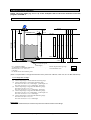
8.4.1 Level measurement (example)
20 mA
Fct.
1.1.2
A
20 mA
Measuring range
probe length
tank height
Fct.
1.5.1
(0)
(1)
(2)
(3)
(4)
4 mA
B
non-measurable
zone
4 mA
Level reference point
(tank height)
Fct = parameter number
Current output measuring range
A= Minimum recommended distance between detection delay and
Non measurable zone
dead zone (Fct 1.1.2 – Fct 1.5.1)
(150 mm)
B = Dead zone at the end of the probe
(Refer to a representation of the physical dimensions of the probe ends: cable twin, cable coax, etc. see BM 100A Manual)
Level configuration example:
Fct 1.3.1 = Level
(0) current output range is smaller than the measuring range.
(1) current output range is equal to the measuring range :
min scale 4 mA (fct 1.3.4) = tank height – probe length + B
max scale 20 mA (fct 1.3.5) = tank height – dead zone
(2) current output range is larger than the measuring range :
min scale 4 mA (fct 1.3.4) = 0.0
max scale 20 mA (fct 1.3.5) = tank height – dead zone
(3) current output range is larger than the measuring range :
min scale 4 mA (fct 1.3.4) = tank height – probe length + B
max scale 20 mA (fct 1.3.5) = tank height
(4) current output range is larger than the measuring range :
min scale 4 mA (fct 1.3.4) = 0.0
max scale 20 mA (fct 1.3.5) = tank height
Please note:
For distance measurement, the reference point is the bottom surface of the flange.
Hycontrol VF SERIES Installation and operating instructions
Page: 32
10/00
8.4.2 Volume measurement (example)
•
•
In order to be able to measure volume with
the VF SERIES, a conversion table
(strapping table) needs to be entered via
®
the PC-STAR 2 program or HART
communicator (see Sect. 8.3).
By means of the strapping table, level
values are allocated to specific volumes
previously calculated or measured.
•
•
•
Unit volume (Fct. 1.2.5): m3
Input table (PC STAR 2):
Volume table
In the case of non-symmetrical tanks, e.g.
tanks with dished bottom, the accuracy of
volume measurement will depend on the
number of entered "level/volume pairs".
The maximum number of pairs (points) that
can be set is 20; the volume is linearly
determined (interpolated) between 2 points.
The table is generally used for volume, but
can be used for mass or volume flow too.
In the following example, 4 sets of data
have been programmed.
Point
"
#
$
%
Tank height (Fct. 1.1.1):
6.00 m / 19.7 ft
Probe length (Fct. 1.1.6):
5.80 m / 19.3 ft
Dead zone (Fct. 1.1.2):
0.40 m / 1.31 ft
Level
0.20 m / 0.66 ft
Volume
0.5 m³ / 17.6 ft3
0.75 m / 2.46 ft
1.00 m / 3.28 ft
5.60 m / 18.4 ft
1.0 m³ / 35.3 ft3
1.5 m³ / 53 ft3
16.80 m³ / 593.3 ft3
Maximum measurable level =tank height - dead zone – (tank height – probe length)
=6,00 m - 0,40 m - ( 6.00 m – 5.80 )= 5.40 m (17.7 ft), equivalent to a volume of 16.30 m ³
Note: The real level can be measured between 0.20 m to 5.60 m. When the level of the product is lower than the probe
end the VF SERIES indicates "tank empty". The VF SERIES is programmed on the basis of a level range between 0 m
and 5.60 m but it can only give a measuring value between 0.2 m(0.44 ft) and 5.60 m(18.4 ft). The size of the Dead
Zone ( 0 m to 0.2 m), depends of the installation and the probe type of the VF SERIES.
Current output I
Function I (Fct 1.3.1):
Range I (Fct. 1.3.2):
Scaling 4 mA (Fct. 1.3.3):
Scaling 20 mA (Fct. 1.3.4):
VOLUME
4 - 20 mA
0.50 m3 , corresponds to 4 mA
16.80 m3 , corresponds to 20 mA
Display
Unit, conversion (Fct. 1.2.5):
m3 (cubic meter)
Hycontrol VF SERIES Installation and operating instructions
Page: 33
10/00
8.5. Description of functions
NOTE: The menu structure is of the structure of the PC
program: PC STAR 2 refered to.
8.5.1 Choice of units
Level/distance units
Select Fct. 1.2.4 Length Unit
• m
• cm
•
inch
• Ft
• mm
• Optional unit
The selected unit is then used for the following functions:
- Dead zone Fct. 1.1.2
- Probe length, Fct. 1.1.6
- Scaling 4 mA value, current output, Fct. 1.3.3
- Scaling 20 mA value, current output, Fct. 1.3.4
The optional unit can only be used as a function of length.
Before selecting this unit in Fct. 1.2.4, it is necessary to
enter the new unit parameters:
. The name of the unit (4 characters), Fct. 1.2.6.1
. The factor of the unit, Fct. 1.2.6.2
The reference of the factor is the millimeter:
If the factor is 10, the optional unit is equivalent to the
centimeter (10 mm).
If the factor is 0.1, the optional unit is equivalent to one tenth
of a millimeter (0.1 mm).
and maximum values are 0 and 60 m (200 ft) respectively.
The factory default value is per your sales order.
NOTE: The VF SERIES does not measure beyond its probe
length.
• Selection of unit, see Sect. 8.5.1.
• Setting ranges for the tank height VF SERIES :
• Tank height:
60.00 m
• Tank height:
6000 cm
• Tank height:
60000 mm
• Tank height:
2362.2 inch
• Tank height:
196.85 ft
•
•
8.5.3 Dead zone/ Time constant / Probe length
Fct. 1.1.2 DEAD ZONE
•
•
Conversion units
The conversion unit can be used to convert the level
measurement into a different unit (usually volume). It is
possible to realise a non-linear function as a factor of the
level.
The tank height setting is also the max limit for the
following function :
- Scale I max. 20 mA, Fct. 1.3.4
The tank height must be greater or equal to the probe
length.
Measurements near the flange may not be precise or
reliable. Therefore, the Dead zone prevents
measurements in this area. The minimum value is equal
to those shown in the table below. Measurement may
not be precise in an area less than this recommended
value. The factory default value is 0.40 m.
Unit and setting range: same as Fct. 1.1.1
TANKHEIGHT.
Probe type
Top Dead zone
for an εr<10
Top Dead zone
for an εr >10
Mono Rod
400 mm / 15.75 ''
300 / 11.81 ''
Options under Fct. 1.2.5 VOLUME UNIT
• m³
l (liter)
• US Gal
Ft3
• bbl (petroleum barrels)
• metric Tons
US Tons
• Kg
m³/h
• Ft3/h
Twin rod
300 mm / 11.81 ''
150 / 5.9 ''
The selected unit is also valid for the following functions:
- Scaling 4 mA value, current output, Fct. 1.3.3
- Scaling 20 mA value, current output, Fct. 1.3.4
Fct. 1.1.3 TIME CONSTANT
• The measurement is filtered with the time constant so as
to avoid abrupt changes in measured values and thus
also in the current output value.
• Range: 001 - 100 Sec
Default value and recommended setting: 5 Sec
•
Display range:
0.00 - 30000.00
0
- 9999999
0
- 7925161
0
- 6599265
0.0 - 999999.9
0.0 - 99999.9
m3
Liter
(US Gal)
(GB Gal)
Ft3
bbl (petroleum barrel)
Conversion measurement requires a conversion table
entered with the PC-STAR 2 program or HART®
communicator. By means of this table a conversion value is
allocated to each level value (level / conversion pairs). The
values are linearly interpolated between 2 points.
Examples of application and setting: see Sect. 8.4.2
8.5.2 Tank height
Fct. 1.1.1 TANK HEIGHT
Mono Cable
400 mm / 15.75 ''
300 / 11.81 ''
Twin cable
300 mm / 11.81 ''
150 / 5.9 ''
Coax
0 mm / 0 ''
0 mm / 0 ''
Fct. 1.1.6 PROBE LENGTH
• This value has to equal to the exact length of the probe.
The only situations for changing this value is if the probe
length has been changed.
• Selection of unit, see Sect. 8.5.1.
• Setting ranges for the probe length VF SERIES :
•
0 to 27.00 m
•
0 to 2700 cm
•
0 to 27000 mm
•
0 to 1063 inch
•
0 to 88.594 ft
• The probe length is at the same time the min limit of the
range for the following function:
Tank height, Fct. 1.1.1
• The probe length is at the same time the max limit of the
range for the following function:
Dead zone, Fct. 1.1.2
The entered value is a fundamental variable for the
calculation of level measurement and its equivalent current
value.
The tank height is defined as the distance between the
bottom of the tank and lower flange surface. The value must
be greater or equivalent to the "probe length". The minimum
Note: When tank is empty, it is possible with software PC
STAR 2 (function F11) to execute an automatic calculation
of the probe length from the dynamic configuration window.
Hycontrol VF SERIES Installation and operating instructions
Page: 34
10/00
•
8.5.4 Display with the PC program “PCSTAR 2”
Fct. 1.2.4 LENGTH UNIT
Use this function to select the unit for displaying level and
distance.
• m
• cm
• mm
• inch
• Ft
• optional unit
If you want to select the optional unit, you have to initialise:
- the name of the new unit (4 character max.) fct. 1.2.6.1
- the conversion factor, fct. 1.2.6.2.
The conversion factor reference is the millimeter:
If the conversion factor is equal to 10, then the new unit is
equivalent to centimeter (10 mm).
If the conversion factor is equal to 0.1, the new unit is
equivalent to one tenth of millimeter (0.1mm).
Fct. 1.2.5 VOLUME UNIT
Use this function to select the unit for volume display.
• m3
& l (litres)
• US Gal
& GB Gal (Gal = gallons)
• ft3
& bbl (petroleum barrels)
3
• m3/h
& ft /h
• metric tons
& US tons
• Kg
Fct.1.2.6 NEW LENGTH UNIT
Appears only if new unit is chosen in fct. 1.2.4
’’ Length Unit’’
Setting VOLUME or ULLAGE VOLUME under Fct. 1.3.1:
Unit for SCALE 4 mA same as in Fct. 1.2.5 VOLUME
UNIT. But Value must be smaller than the maximum
value in the conversion table and smaller than the
SCALE 20 mA (Fct. 1.3.4).
Fct. 1.3.4 SCALE 20 mA
•
•
•
This function is used for Imax = 20 mA to define the
upper value for level, distance, volume or ullage volume
Setting LEVEL or DISTANCE in Fct. 1.3.1: Unit for
SCALE 20 mA as in Fct. 1.1.1 TANKHEIGHT. The value
set has not to be greater than the tank height (Fct. 1.1.1)
Setting VOLUME OR ULLAGE VOLUME in Fct. 1.3.1:
Unit for SCALE 20 mA same as in Fct. 1.2.5 VOLUME
UNIT. The value set must be greater than the SCALE 4
mA (Fct. 1.3.3), otherwise error during Parameter
Check.
Application and programming examples: see Sect. 8.5
Fct. 1.3.5 ERROR DELAY
This function is available on the HART® communicator when
4-20 mA / E=22 mA is chosen.
The delay defines the amount of time, in the event of an
error, before the VF SERIES goes to 22 mA. After the
problem occurs and before the end of the delay, the
measurement value (and also the current value) is frozen.
Fct. 1.2.6.1 NAME OF NEW LENGTH UNIT
Name of new unit ( max. 4 characters)
Fct. 1.2.6.2 CONVERSION FACTOR
The conversion factor reference is the millimeter:
If the conversion factor is equal to 10, then the new unit is
equivalent to centimeter (10 mm).
If the conversion factor is equal to 0.1, the new unit is
equivalent to one tenth of millimeter (0.1mm).
8.5.5 Analogue Output
Fct. 1.3.1. FUNCTION I
Use this function to select the measured variable.
• LEVEL
• DISTANCE
• VOLUME
• ULLAGE VOLUME
Fct. 1.3.2 RANGE I
Use this function to define the current output value during
error condition.
E = Error at 22 mA.
•
•
4-20 mA (hold last measured value when error occurs)
4-20 mA / E=22 mA (drift to 22 mA in case of error).
Fct. 1.3.3 SCALE I1 min. 4 mA
•
This function is used for Imin = 4 mA to define the lower
value for level, distance, volume or ullage volume
(scaling 4 mA).
•
Setting LEVEL or DISTANCE in Fct. 1.3.1:
Unit for SCALE 4 mA same as in Fct. 1.1.1
TANKHEIGHT. Value must be smaller than SCALE 20
mA
Hycontrol VF SERIES Installation and operating instructions
Page: 35
10/00
8.5.6 User Data
Fct. 1.4.4 TAG
Tag name of the device can be displayed 8 ASCII
characters.
Note: Not all the characters can be used. "Tag name",
"descriptor" and message are recorded in a special format
(Packed ASCII). Only the characters in the following table
can be used.
@
A
B
C
D
E
F
G
H
I
J
K
L
M
N
O
P
Q
R
S
T
U
V
W
X
Y
Z
[
\
]
^
_
Space
!
“
#
$
%
&
’
(
)
*
+
’
.
/
0
1
2
3
4
5
6
7
8
9
:
;
<
=
>
?
Fct. 1.4.5 SERIAL NUMBER
Identifies each VF SERIES. Can not be changed. This
number defines the "Device ID" of the HART® Long
Address.
Fct. 1.4.6 FRENCH COMMISSION NUMBER
This number is factory set. Refer to this number in case of
warranty or service claims.
Fct. 1.4.7 GERMAN COMMISSION NUMBER
This number is factory set. Refer to this number in case of
warranty or service claims.
Fct. 1.4.8 Optional
Up to 15 optional ASCII characters can be written.
Fct. 1.4.9 PROBE TYPE
Probe type attached to the flange, as specified in the order.
Fct. 1.4.10 CHECKSUM
ROM Checksum. Identifies the software version of the
device. It allows also to detect problems with the micro
controller. A test of this checksum is performed in the
factory.
The threshold filters non-valid reflections (example:
heating tube). The VF SERIES measures only those pulses
with an amplitude above the threshold.
The amplitude of the reflections is related to the dielectric
constant of the product.
To set the threshold correctly, it is necessary to know
approximately the amplitude of all reflections along the
probe (level reflection and also non-valid reflections). An
oscilloscope function which gives a view of all the reflections
along the probe.
Default value for threshold is 200 mV in amplification factor
3 (gain 3).
The minimum threshold is 50 mV Gain 3.
The maximum threshold is 2500 mV Gain 0.
Gain
0
1
2
3
Amplification
1.05
2.10
4.37
8.93
The gain stage is assigned according to the strength of the
reflection.
With amplification factor 0 (gain 0), the reflection is not
amplified.
With gain 3, the reflection is amplified nearly by 9.
The VF SERIES automatically changes the gain. In order to
ensure that the processed reflection is maintained within a
range of values that the electronics can most efficiently
track.
The threshold is recorded with the same amplification factor
as the reflection.
If the reflection level gets smaller, the VF SERIES will
increase the gain and the reflection will be amplified. The
threshold level will be equally amplified.
8.5.7 Threshold / Distance input/ Search Probe End
Dynamic Configuration
The amplitude and the amplification of the level pulse give
an indication whether the device is following the correct
pulse. For a product with εr > 80, the amplification factor
should be 0 or 1 (depending on the probe type). For εr< 10
the amplification factor should be 2 or 3 (gain 2 or 3).
Normally the threshold does not need to be adapted. In
some applications where reflections occur due to nozzles
etc, a higher threshold setting can be necessary.
Note: It is recommended to not have a full (or empty) tank
when setting the threshold.
Same
reflection
The example shows that when the reflection level gain
changes, the threshold in both cases rises approximately to
a level of 50% signal amplitude.
To understand the principal use of this parameter, it is
important to study the measuring principle:
As the distance between the flange and the product surface
rises, the amplitude of the reflected pulse gets smaller. The
threshold adapts automatically in the same manner.
Hycontrol VF SERIES Installation and operating instructions
Page: 36
10/00
The level in the tank is between 2 and 4 meters:
8.5.8 SERIAL I/O
HART® PROTOCOL:
2m
The HART® protocol is a communications protocol of the
"HART® Communication Foundation". In addition to the
Threshold
"universal commands" and "common practice commands"
there are "device-specific commands" to access all the rest
of the parameters and functions of the VF SERIES.
Furthermore ask for the "device description" (DD) for the VF
SERIES, which can be used for universal HART® control
units, such as the HART® Communicator or SIPROM.
The standard hardware platform for HART® is the current
The threshold can not output 4-20 mA with superimposed FSK signals. For
decrease anymore than HART®-Multidrop (max. 15 devices on one bus), the current
The level value in the tank decreases:
Minimum value
output is automatically set to a constant 4 mA
4m
Gain 3
Level
2m
= 50 mV gain 3
4m
Non valid reflection
Fct. 1.6.2 ADDRESS
• This function is used for entering valid addresses from 0
to 15 (HART® protocol).
• If several devices are operated on one digital bus or via
HART®-Multidrop, each device must be set to an
individual address under which it can then be addressed
on the bus.
• The default value is the address "0".
8.5.9 STRAPPING TABLE
This function of the device allows the threshold to remain in
the same proportion as the reflection amplitudes.
Refer to the annexe for further information on how to adjust
the threshold.
Fct. Distance Input
It is not recommended to use this function in normal
circumstances. Only in case of problems, it is to be used.
This function forces the VF SERIES to search for the
product in a certain area along the probe. For instance, if
The VF SERIES probe is mounted on a tank while this latter
is switched on, it may display permanently a full tank. To
resolve such a problem, two way exist:
1. switch off the VF SERIES and then switch it on.
2. Enter in a distance value where the product is
supposed to be.
Fct. Detection Delay
Allows to define a zone below the flange in order to mask
noise. This value has to be smaller or equal to the value of
the dead zone set in 1.1.2.
The detection delay is especially useful for eliminating
reflections due to the nozzle.
See Volume Measurements section.
8.5.10 TESTS
Fct. Test Output
This function tests the current output. It forces the output to
a certain value while the accuracy can be checked with a
reference ammeter:
•
An ammeter must be connected to the loop for this test.
•
Select a current value (for PC STAR 2)
4 mA
8 mA
12 mA
16 mA
20 mA
22 mA
The connected ammeter shows the measured current
value.
When exiting the test, the current output will return to the
measured or previous value.
•
•
Fct. Search Probe End
The probe length can be measured automatically. This is
necessary when the probe length was modified (cut).
If the VF SERIES does not succeed in finding
automatically the probe length, there are three possibilities:
1. The threshold is not set correctly. Follow instructions to
set it to a lower value.
2. The electronic offset is incorrect (Service Menu).
3. The probe type selected is incorrect (Service Menu).
4. The tank is not empty.
Contact the Service Department in case of an unsuccessful
auto-measurement of the probe.
Fct. Reset VF SERIES
Restarts the device.
Hycontrol VF SERIES Installation and operating instructions
Page: 37
10/00
8.5.11 SERVICE
8.5.13 CALIBRATION
Fct. 1.1.2 Measurement Offset
Function for manual zero adjustment. Reference point for all
measurements is the lower flange surface of the instrument.
It is not recommended to modify this parameter, except for
Hycontrol Service Personnel.
Fct. Current Output
This function is used to calibrate the current output. First a
reference ammeter has to be connected to the VF SERIES
in order to measure the actual loop current. The function
fixes the current to 4.0 mA. Enter the actual current value
measured with the ammeter (e.g. 4.01 mA). The VF SERIES
then calibrates automatically the current output. Repeat this
operation in case the accuracy of the displayed current
output value is not satisfactory. As a final step repeat the
same procedure for the 20 mA value.
Fct. 2.4 and 2.5 Electronical / Mechanical Calspeed
These two constants are calibration factors which convert
the measured time between the reference pulse and the
level pulse into a distance (length).
There are 2 calibration factors. One because the pulse
crosses the electronic board before entering the probe, and
the other one because there are several probe types and
each probe type geometry has an influence on the
propagation of the wave.
Each electronic block has its own electronic factor.
Each probe type has his own mechanical factor.
Hence each device is calibrated with its specific probe.
For calibration, you can modify the offset in order to adjust
value supplied by VF SERIES:
If the value indicated by the VF SERIES is for example 2505
mm (98.6 ''), and the true value is 2500 mm(98.43'') then 5
mm /0.2 " (2505 – 2500) has to be added to the offset.
An automatic measurement of the offset can be performed
with the dynamic configuration function.
This automatic function does not give an accurate value. It
has to be adjusted manually.
Fct. 2.1 Electronic Offset
This parameter allows to move the signal vertically. Says to
add or to substract an offset to the signal zero reference. It
allows to hide non valid signal noise, because only positive
signals are measured.
In the example below the amplitude of the non valid pulse is
about 30 mV. Increasing the offset by 30 mV, maskes the
noise completely.
Fct. 1.1.3 Application Type
Sets the process configuration.
A.
B.
Amplitude
= 30 mV
1 product, 1 level
2 products, 1 level
Option A is the standard mode. Only one product is in the
tank and the dielectric constant of the upper medium
between the flange and the lower product level is 1.0 (air)
The second option is used in case the dielectric constant of
the upper medium between the flange and the lower product
level is not 1.0 . In this second case the function 1.1.4 can
be used to specify the εr of the upper product.
8.5.12 APPLICATION
Fct. Voltages values
The non-valid signal disappeared, but the amplitude of the
level pulse decreased too.
The voltage values are:
Power supply (+/- 3 volts)
Time Base supply (Voltage Control Oscillator)
These values are used only by the Hycontrol Service
Department.
Fct. Watch Pulses
This function can be only used by the Hycontrol Service
Department.
This function gives additional information on the captured
signal. It is useful in analysing if the VF SERIES is tracking
the right level reflection.
Fct. Histories
These two functions record the status history of the device.
The two functions store the last 24 status or error messages
in a special non volatile memory.
Hycontrol VF SERIES Installation and operating instructions
Page: 38
10/00
Normally for standard application this parameter should not
be modified.
This parameter should be only modified under supervision of
HYCONTROL Service.
8.5.16 WATCH STATUS
Displays the status of the device.
Allows to set all user parameters to their default values. This
can be useful to reconfigure completely a device, which also
disables the maintenance password, in case it was
forgotten.
Tank Full
Tank Empty
Level Lost
EEPROM Error
RAM Error
ROM Error
Digitising Error
Gain Error
Offset Error
Positive Voltage Error
Negative Voltage Error
VCO1 Voltage Error
VCO2 Voltage Error
Checksum Error Bank Customer 0
Checksum Error Bank Factory 0
Checksum Error Bank Customer 1
Checksum Error Bank Factory 1
Delay out of limits
Reference Not Found
Flange Not Found
Reference Lost
First Start
Error reprogramming FPGA
Error Parity FPGA
Fct. Factory Reset
Each status is explained in sections 8.2 and 8.3.
Fct. Auto Offset Measure
See Section Fct 1.1.2
Fct. 2.6 Set Ref. Frequency
The function allows to re-enter the frequency reference
parameter after a factory reset. The value must be recorded
before the reset and re-entered to make sure that the
instruments works correctly. The parameter was measured
during the assembly process of the instrument and cannot
be determined without special equipment.
8.5.14 EEPROM RESET
Fct. User Reset
Note: Before using this function, contact the HYCONTROL
Service Department. This function resets all the factory
parameters. It is essential to record the Offset of Measure,
the Electronic Offset, Electronics Speed Calibration and
Mechanical Speed Calibration values and Reference
Frequency value before this function is activated. These
values can be then re-entered after the reset. After a reset,
the current output must be calibrated again.
8.5.17 Display of the PC program (PC STAR 2)
Language of displayed texts
Choose one of the following languages for the display ;
• GB/USA : English
• D
: German
• F
: French
8.5.15 ACCESS RIGHTS
Fct. Maintenance Password
8.5.18 Hardware test
The maintenance password is a customer password. It
allows to protect the access of the device configuration
menu. Read only values can only then be accessed, like the
measurement values and the status, without the password.
At each start up, the VF SERIES executes automatically a
hardware test. Several voltage values as well as other tests
of the audio signal are performed.
The password must contain exactly 9 characters and these
characters must be E, R or U. The password is displayed in
a scrambled format. It allows HYCONTROL to decode the
password in case it was forgotten.
During normal operation, the VF SERIES performs real time
tests in order to guarantee a correct and reliable operation.
In case of an unlikely problem within the electronics, the VF
SERIES records into a non-volatile memory. The function
watch status can be used to access this memory.
The password must contain exactly 9 characters and the
only usable characters are E, R or U.
1st character
2nd character
3rd character
4th character
5th character
6th character
7th character
8th character
9th character
R
I
T
I
Q
R
R
Q
R
Q
E
T
J
T
F
E
E
F
E
F
U
U
Z
U
V
U
U
V
U
V
The above table can be used to decode the password.
Hycontrol VF SERIES Installation and operating instructions
Page: 39
10/00
8.6 Warning and error messages during configuration
Status Message
Invalid selection
Entered parameter too large
Entered parameter too small
Too few data bytes
In write protect mode
Update failure
Lower range value too high
Applied process too high
Not in proper current mode
Cannot change active password
Table non dull
Lower range value too low
Applied process too low
Upper range value too high
Multidrop mode
Illegal password symbol
Upper range value too low
Invalid units code
Invalid function
Invalid password
Access restricted
Invalid range units code
Device busy
Not implemented
First Parameter too high
(first member of the pair too high)
First Parameter too low
(first member of the pair too low)
Second Parameter too high
(second member of the pair too high)
Second Parameter too low
(second member of the pair too low)
Meaning
Non valid item was chosen
Value too large
Value too small
There were not enough bytes transmitted received
Write protected
Measurement failure of the VF SERIES
Lower range value must be smaller
Message appears when the PV range values are not adapted (method Apply
values)
Appears if the current output is not fixed when we execute method DAC Trim
Appears in the case the password is incorrect
Appears if the volume table is not dull
Lower range value must be bigger
Message appears when the PV range values are not adapted (method Apply
values)
The value of the range is incorrect. Upper range value must be smaller
Appears in multidrop mode when wanting to fix a value on the current output.
In this mode it is not possible to set the current output to certain value
The characters of the passed password are incorrect. They must be ‘E’, ‘R’
or ‘U’
Upper range value must be higher
The unit is not supported by the VF SERIES
The result of the function is incorrect.
Specialist menu blocked because the password is incorrect.
This message appears when trying to modify a parameter and the customer
password is enabled.
Appears if the unit of the range is incorrect
Appears when the device is in search mode or if it is executing a function.
Appears if the command sent to the device is not implemented in the device.
Some parameters are handled in pairs. The two items are updated at the
same time when one of the following messages appears and one of the
items is incorrect. These pairs are :
•
Tank height / Probe length
•
Dead zone / Detection delay
•
Threshold value / Threshold distance
•
Optional unit name / Optional unit factor
•
Offset of measure / Period of measure
•
Electronics Calspeed / mechanical calspeed
•
Epsilon R / “Set value” of Electronic offset
Hycontrol VF SERIES Installation and operating instructions
Page: 40
10/00
8.7 Warning messages during measurement
Message
Configuration Changed
More Status Available
Primary Variable Analog Output Fixed
Analog Output Saturated
First Start
Tank Full
Tank Empty
Level Lost
Meaning
Configuration parameter was changed.
Command 48 must be executed to detail the status better. (menu Watch
Status)
Is displayed when:
•
Device is set in Multidrop Mode
(Polling Address ≠ 0)
•
Fixed Current Mode is entered
(during Loop Test and DAC Trim)
During normal operation the maximum value for the analogue output is 20
mA. The analogue output saturation error flag is set in case the
measurement exceeds the signal current output range.
This message appears only when the serial number is 0 or 16777215.
Normally this message can occur only in production before the calibration
of the device.
The VF SERIES indicates that the product level is in the "dead zone",
meaning that the tank is full.
The VF SERIES indicates that the level is bellow the probe end. The VF
SERIES cannot measure down to the tank bottom but only down to the end
of the probe.
The VF SERIES indicates when it loses the level reflection. This can occur
in case there is no reflection with an amplitude higher than the threshold
value. Measuring values are frozen. If the mode 4-20 mA / error 22 mA is
selected then the current output is fixed to 22 mA after the selected delay
time.
Hycontrol VF SERIES Installation and operating instructions
Page: 41
10/00
8.8 Error messages during start up or measurement
The following list table all error messages that can trigger the current output to be set 22 mA if the mode 4-20/Error22 is
selected. Measuring values are then frozen.
Message
EEPROM Error
RAM Error
ROM Error
Checksum Error Bank Customer 0
Checksum Error Bank Factory 0
Checksum Error Bank Customer 1
Checksum Error Bank factory 1
Digitizing Error
Reprogramming FPGA
Gain Error
Offset Error
Positive Voltage Error
Negative Voltage Error
VCO1 Voltage Error
VCO2 Voltage Error
Delay Out of Limits
Reference Not Found
Flange Not Found
Update failure
Meaning
This message can occur during start up of the device (after Hardware
tests). If it occurs, there is a problem with the non-volatile memory.
Please contact HYCONTROL Service.
This message can occur during the start up of the device (after Hardware
tests). If it occurs, there is a problem with the internal micro-controller
memory. Please contact HYCONTROL Service.
This message can occur during the start up of the device (after Hardware
tests). If it occurs, there is a problem with the internal micro-controller
memory. Please contact HYCONTROL Service.
This message can occur during the start up of the device (after Hardware
tests). If it occurs, there is a problem with the EEPROM or with the
function which recalls the parameters saved in the EEPROM. Parameters
are saved in a non-volatile memory (EEPROM). There are 4 banks, 2 for
each type of parameters (customer or factory). If there is a problem with
the first bank (0), then the VF SERIES gets the parameters values from
the second bank (1). If the VF SERIES indicates only a problem with the
first bank, it means that it succeeded in getting all the parameters thanks
to the second bank. In this case the device can measure.
This message can occur during start up of the device (after Hardware
tests). If it occurs, there is a problem with the EEPROM or with the
recalling of the parameters saved in EEPROM. Parameters are saved in
a non volatile memory (EEPROM). There are 4 banks, 2 for each type of
parameters (customer or factory). If there is a problem with the first bank
(0), then the VF SERIES tries to get the parameters values from the
second bank (1). If the VF SERIES indicates only a problem with the first
bank, it means that it succeeded in getting all the parameters thanks to
the second bank. In this case the device can measure.
This message can occur at the start up of the device (after Hardware
tests). Refer to Bank 0 and re-start the device several times. If the
problem remains then contact HYCONTROL Service.
This message can occur at the start up of the device (after Hardware
tests). Refer to Bank 0 and re-start the device several times. If the
problem remains then contact HYCONTROL Service.
This message occurs in case of a problem during sampling the audio
signal. The electronics doesn't get a valid image of the audio signal. The
measurement may be incorrect. Please contact HYCONTROL Service.
Reset of the component FPGA.
This message occurs in case of Hardware problems with the signal frontend amplifier. The error occurs in case one of the 4 amplifications, do not
work correctly. Please contact HYCONTROL Service.
As with the sampling and the Gain errors, this message occurs in case of
a problem with the electronic offset of the audio signal. Please contact
HYCONTROL Service.
Occurs when the +3 Volts power supply is out of limit. Please contact
HYCONTROL Service.
Occurs when the -3 Volts power supply is out of limit. Please contact
HYCONTROL Service.
Occurs during a problem with the time base. Please contact
HYCONTROL Service.
Occurs during a problem with the time base. Please contact
HYCONTROL Service.
Occurs during a problem with the time base. Please contact
HYCONTROL Service.
Occurs during a problem with the time base. Please contact
HYCONTROL Service.
Occurs in the case of a problem with the time base. The error indicates a
mechanical problem (bad contact) between the converter's electronic
block and the flange connection. Please contact the HYCONTROL
Service Department.
Warning message to indicate that the VF SERIES is not able to measure.
Hycontrol VF SERIES Installation and operating instructions
Page: 42
10/00
8.9 Start-up
Please refer to following table in case of problems.
8.10 Faults and symptoms during start-up and measurement
•
All possible failures are listed in this section, with a corrective action.
•
Please read this section before contacting HYCONTROL Service.
Fault / Symptom
Current Output value < 4 mA
Reads 22 mA.
Cause
Corrective action
The calibration of the current output Execute the calibration if you have the
is incorrect.
specialist access or contact Hycontrol Service.
Connection of the device is
Check the connection between the device and
incorrect.
the power supply.
No power supply.
This happens in case the range 4-20 mA / error
An error has occurred.
22 mA is selected.
Check the status of the device by selecting the
status window (F8) or enter the status (4.O)
menu of the HART® communicator.
The device is in its start-up phase.
The value at the current output
does not correspond to the value
at the display (PC STAR 2 or
HART® communicator).
Data communication via the
digital interface is not working.
Settings of the current output are
incorrect.
The communication parameters of
the computer are set incorrectly.
Bad connection to the interface.
Current output value is < 4 mA
Current output value is = 22 mA
Wait 50 seconds. If the current value drop to a
value between 4 and 20 mA, and goes
immediately back to 22 mA, consult
HYCONTROL Service.
Configure output as described in Sect. 8.6.8
(Fct.1.3.0).
Check computer setting (polling address).
Check connection.
Consult HYCONTROL Service.
VF SERIES is in its start up phase, wait 50
seconds and try again.
If the problem persists then contact Hycontrol
Service.
Fault / Symptom
The VF SERIES indicates an
incorrect level value.
Cause
The VF SERIES measures a nonvalid reflection.
The tank is empty, and the VF
SERIES indicates a level.
In case the VF SERIES indicates a
level, a valid pulse was found.
Check the probe for disturbances
such as heating tubes or product
build up (clogging).
The threshold is not adapted.
See section (8.5.7) to adjust it.
The threshold is not adapted.
See section (8.5.7) to adjust it.
The tank is full, and the VF
SERIES indicates a level or
empty tank.
The tank is not empty nor full,
and the VF SERIES indicates an
empty or full tank.
Hycontrol VF SERIES Installation and operating instructions
Corrective action
In the case the indicated level is close to the
nozzle, increase the detection delay and the
dead zone with the same ratio or increase the
threshold level if the full measurement range is
essential.
In any case use the PC STAR 2 oscilloscope
function to visualise and to analyse the
application.
The threshold level must be adjusted so that it
masks the disturbances. It permits also to give
enough margin for the level pulse.
Very large pulses along the measurement signal
(same amplitude as the initial pulse) can be
caused by a probe which is touching the nozzle
or the tank side (see mounting guideline
section).
Analyse the signal with PC STAR 2. Simply
adjust the threshold (dynamic configuration
window). See section (8.5.7)
Page: 43
10/00
8.11 Oscilloscope Function of PC STAR 2 and Threshold
What’s the purpose of the signal oscilloscope of PC STAR 2 ?
This function analyses the position and amplitude of each pulse between the initial pulse and the probe end. It helps in
analysing incorrect measurements by visualising the threshold and pulse together.
In case of a measurement problem, do not hesitate to use this function. It visualises all pulses along the probe, including
the initial pulse, flange and level pulses (if not empty) and non product reflections!
The signal function of PC STAR 2 helps to adapt measurement-related settings like the detection delay, or the threshold
level.
Moreover it helps to understand how the VF SERIES works. A screen plot of this function will help in understanding the
instrument's application. The signal can be printed or saved as an Excel file and sent by Email.
How to use the Signal Function:
The plots below show typical measurement signals recorded with the PC STAR 2-oscilloscope function. Plot 1 is a signal
captured with a rod or a cable probe and an amplification factor of 1 (gain 1). Plot 2 shows the same probe with an
amplification factor 2 (gain 2). Plot 3 and 4 are traces recorded with a coaxial probe and the same amplification factors
as plot 1 and 2.
The difference between the coax probe and the other probe types is the missing flange pulse. The missing pulse
explaines why it is advantageous to use a coax probe for applications where a certain dead zone at the top of the probe
is not acceptable. The level reflections of the coax probe can move up to the top of the flange without being disturbed by
the flange pulse.
The signal plots of both probe types show how the level reflection amplitude changes with two different amplification
factors gain 1 and gain 2. Remark that only the amplitude of the level reflections changes but not the amplitude of the
initial, neither the flange reflections. Amplification is only applied in the measuring zone.
In certain application, the signal along the probe contains non-valid reflections as shown in the following plot. The
reflections can have various origins but have always the characteristic of a real product surface pulse. This means that
the non-valid reflections get amplified like real level reflections.
Hycontrol VF SERIES Installation and operating instructions
Page: 44
10/00
What is the use of the Threshold?
The purpose of the threshold level of the VF SERIES is to mask such non-valid reflections.
The threshold level, as shown in plot 6 is not a constant level along probe signal, but an exponentially falling function.
If the amplitude of the threshold level was set at 1 m to 400 mV, it will be reduced to 250 mV at 10 m probe length. The
exponentially falling function was chosen because the amplitude of the level pulse as well as the amplitude of the nonvalid reflections decrease with the same kind of function, and the amplitude/threshold ratio remains the same along the
probe (following the same attenuation curve as the level pulse).
In the case the probe is short (<Ω 3m), the reduction of the threshold amplitude is not very significant.
The factory threshold setting will be suitable in all normal applications. Adjustment is only necessary in situations where
the εr is very low and installation conditions are difficult.
How to use the Threshold?
The smaller the εr of the product is, the more important the correct threshold setting will be. In order to adjust the
threshold level, it is absolutely necessary to know the product level (reflection amplitude) inside the tank. The ideal point
where to make a threshold adjustment is when the product covers about 50 cm the probe end. If the level is to high, the
product will mask the non-valid reflection. And if the product doesn't reach the probe end, one won't manage to evaluate
the ratio of the level pulse and the non-valid pulses. In this case, The easiest way to adjust the threshold level is to
capture a complete trace of the probe signal (trace from the initial pulse down to the probe end) with the oscilloscope
function (F7) of the PC STAR 2 software.
The threshold level is adjusted correctly so that all non-valid reflections are below and the product surface pulse is
above the threshold level. If possible, the threshold level should be half way between the non-valid signal and level
signal. If the εr of the product is low, it is possible that the pulse of the probe end is visible too on the screen. This pulse
does not have to be masked by the threshold level (as it will be seen moving further away in time as the product level
increases). Adjust now the threshold level according the different pulse amplitudes. It is advised to keep a margin
between the threshold level and the pulse amplitudes in order to cope with possible fluctuations in terms of amplitude.
The amplitude of the product reflection increases with increasing level, and vice-versa.
In case the threshold level was adjusted to a value higher than the product pulse, the VF SERIES will not find the pulse,
even after changing the amplification factor. In case the threshold level was adjusted too low (below non-valid pulse
amplitude level), the VF SERIES will find a non-valid pulse next time the product level drops below the probe end.
The minimum threshold is 50 mV at gain factor 3.
Hycontrol VF SERIES Installation and operating instructions
Page: 45
10/00
Hycontrol VF SERIES Installation and operating instructions
Page: 46
10/00
8.12 Calculation of the measured value
VF SERIES measures the time between reflections and converts it into a distance or a level value with the
following formulas:
Delta T = (Time between Initial Pulse and Level Pulse) / 2 (µS)
Calspeeds = (Electronic Calspeed) * (Mechanic Calspeed) (µS/mm)
Offset = Distance between Initial pulse and bottom surface of the flange (mm)
r = Dielectric constant of first medium under the flange, normally 1.00.
ε
Distance =
Level =
DeltaT
Calspeeds
− Offset
εr
Tank Height − Distance
The measured time between the initial pulse and the level pulse is translated into length by the Calspeeds
product. This primary distance is corrected by the offset and is thus standardised to the reference point ( =
flange). This primary distance is divided by the square root of εR (if there is only one product in the tank, the
εr is 1.00 (air)).
The level is calculated as the difference between tank height and distance. All items of information
(excepted Delta T) can be accessed via the digital communication.
Hycontrol VF SERIES Installation and operating instructions
Page: 47
10/00
9. Power supply
9.1 Technical data
Vsupply
Vinput
Rcable
R meter
RHART
mA meter
HART
MASTER
nominal power supply voltage Vinput
maximum Vinput
minimum Vinput
24 VDC
35 VDC
see graph below
Input voltages above 35 VDC may damage the instrument. Furthermore, input voltages above
35VDC or below the specified voltage may cause a faulty measurement or may trigger the
instrument to reset cyclicly.
loop resistance Rloop
minimum Rloop
maximum Rloop
®
HART communication resistor RHART®
Hycontrol VF SERIES Installation and operating instructions
RHART® + Rcable + Rmeter
0Ω
750 Ω
250 Ω (recommended)
Page: 48
10/00
The function A in the diagram above specifies the minimum voltage at the terminals of the VF
SERIES. The voltage drop over the total loop resistance (Ampere-meter resistance Rmeter plus wiring
®
resistance Rcable plus HART communication resistance RHART®) has to be taken in consideration for
the calculation of the minimum power supply voltage. Function B gives an example of a voltage drop
caused by a 250 Ω resistance. The voltage of the power supply has to be at a loop current of 20 mA at
least:
Vsupply min20 = 20 mA * 250 Ω + Vinput min20 = 5 V + 10 V = 15 V
In order to cover the full current range of 4 to 22 mA the voltage drop at 4 mA has to be verified.
Vsupply min4 = 4 mA * 250 Ω + Vinput min4 = 1 V + 18 V = 19 V
This means that with a loop resistance of 250 Ω a power supply voltage of 19 V will be sufficient to
cover the 4 to 20 mA range of the instrument.
9.2 4 to 20 mA converters
Vinput
Barrier supply
Rmeter
Rcable
Barrier
RHART
HART
MASTER
Function A in the graph above (chapter 9.1) can be also used to find out whether a certain 4 to 20 mA
converter is adequate for the operation with the VF SERIES.
Most of the converters are specified to deliver a minimum output voltage at 20 mA loop current
Vout min20. This voltage must be above function A at 20 mA loop current, means greater than 10 V. The
second condition for the converter is the output voltage at 4 mA. Either it is specified too or it can be
calculated with the value of the internal series converter resistance.
It is important to use only converters, which are equipped with a SMART function. Neither the
®
PCSTAR software nor the HART communication run when the converter is not equipped with this
option.
9.3 Sunshade
If the device is exposed direct sun exposition a sunshade is recommended.
9.4 Ex Applications
Ex approved VF SERIES instruments must be used with certified Ex equipment only. The maximum
electrical safety values of the VF SERIES that are listed on the data plate must be respected in any
circumstances. The minimum voltage supply values that are described in 9.1 must be respected for
the proper functionality of the VF SERIES. Furthermore, the connected equipment must be HART
compatible in order to use communication software or the HHC communicator.
Hycontrol VF SERIES Installation and operating instructions
Page: 49
10/00
10. Certificates and approvals
10.1 CE Manufacturer’s declaration
DECLARATION OF CONFORMITY
We,
HYCONTROL LTD
Larchwood House
Orchard Street
Redditch
Worcs B98 7DP
United Kingdom
declare on our own responsibility that the product
REFLEX VF SERIES 24V DC
to which this declaration refers, is in conformity with the following standards:
•
•
•
•
EN 50081 - 1 : 1993 - 3
EN 50082 - 2 : 1995 - 3
pr EN 50178 : 1994 - 8
EN 61010 - 1 : 1993 - 4
in accordance with the provisions of Directives 89 / 336 / EEC and 73 / 23 / EEC.
February. 2000
(Signed: Company Management)
Hycontrol VF SERIES Installation and operating instructions
Page: 50
10/00
11. Order information
Technical information relevant to the order
REFLEX VF SERIES
♦ Process connection or flange: ... ________________________________________________
♦ Sensor material: ........................ ________________________________________________
♦ Seal: ..........................................
Viton
Kalrez
Other___________________________
♦ Sensor type: ..............................: _______________________________________________
♦ Power supply: ............................
24V DC Standard
24 V DC Exi
Brand :
♦ Sensor length
♦ Connection ................................ DIN connector
M16 Connector
Special items
Additional calibration
Others: ....................................... ________________________________________________
12. External standards, codes and directives
EN 500014: 1977 (VDE 0170/0171 part 1/1.87). Electrical apparatus for potentially explosive atmospheres;
General requirements
EN 500020: 1977 (VDE 0170/0171 part 7/4.92). Electrical apparatus for potentially explosive atmospheres;
Intrinsic Safety "i"
DIN VDE 0170/0171 part 13/11.86. Requirements for equipment of Zone 10 [in German}
DIN EN 50081-1 (VDE 0839 part 81-1): 1993-03. Electromagnetic compatibility (EMC); General emission
standard, Part 1: Residential, commercial and light industry
EN 50082-2: 1995-03. Electromagnetic compatibility; generic immunity standard, Part 2: industrial environment
NAMUR Recommendation for the interference immunity of electronic devices (EMC), 18-05-1999 [in English}
DIN EN 61010-1 (VDE 0411 part 1): 1993-04. Safety requirements for electrical equipment for measurement,
control and laboratory use; General requirements [in German]
Directive 89/336/EEC (CE marking)
13. Quality assurance
HYCONTROL LTD is certified to
• DIN ISO 9001 / EN 29001
Hycontrol VF SERIES Installation and operating instructions
Page: 51
10/00
Annex A: Technical specifications
1
Range of application
Distance, level, volume and reflection measurement of liquids,
slurries, solids and particulate material on storage and process tanks
or containers and also in stilling wells
2
Mode of operation / system structure
Micropulse TDR, with digital signal processing; compact device,
modular design
3
Input
Measured variable
Measuring range
Rate of change in level
4
Primary variables: distance, reflection; derived variables: level,
volume
Min. tank height: 0.15 m
Max. measuring range: 24 m
< 10/min
Output
Ex-ia current output HART®
Type:
Current range:
Temperature drift:
Accuracy/linearity:
Supply voltage 2:
Load impedance:
Max. electrical values
Passive (current sink);
4-20 mA (error 22 mA);
4 mA constant for HART®-Multidrop
< 0.02 % / °K
0.05 % (rel. 20 mA; 25°C)
20-30 V (terminals 1 and 2 see 9.
Power supply).
0 – 750 Ω
see certificates
Same characteristic
5
Measuring accuracy
Error of measurement
Repeatability
Measured-value resolution
Effect of ambient temperature
6
6.1
6.2
Operating conditions
Installation conditions
Ambient conditions
Hazardous locations
CENELEC
Ambient temperature at signal converter
Product temperature
Environment class
Protection category
Shock resistance
6.3
Vibration endurance limit
EMC
Product conditions
Physical properties
Relative permitivity
Reference conditions and error curves: see Sect. 5.1 and 5.2
< 0.5 × error of measurement
VF SERIES: 1 mm.
No significant effect on measured value( 1 ppm / °K);
(see also signal output accuracy).
Avoid interference reflections and multiple reflections
Approvals for: 1G EEx ia IIC T6…T3
1G EEx ia IIB T6…T3
1/2 D T 100°C EEx ia
-20°C to +55°C
-50°C to + 90°C
Higher on request
Locations exposed direct to open-air climate, D1 Severity in
conformity with EN 60654-1
(signal converter) IP65
Impact test according to EN 61010, Sect. 8.2 with 0.5 J energy; drop
test to prEN 50178
IEC 68-2-6 and prEN 50178 (10-57Hz:0.075mm/57-150 Hz:1g)
EN 50081-1, EN 50082-2
No effect on measurement results; to ensure reliable measurements,
the relative permitivity (εr ) should have the following minimum
values:
εr > 1.5; for coax probes
εr > 1.8; for twin cable probes
εr > 2.3; for mono cable probes
Limitations
Operating pressure
Electrical connection
User language
Units of measurement
7
Design
8
User interface
9
Power supply
24 V DC
Power consumption
Sticky products
Standard: max. 4 bar (higher on request)
DIN Connector.
PG 13.5
German, English, French
Length: m, cm, mm, inch, ft, %
Volume: m³, Liter, US Gal, GB Gal, ft3, bbl, %
Conversion unit: any text
20-30 V DC
Typically <70 mW.
Hycontrol VF SERIES Installation and operating instructions
Page: 52
10/00
Annex B: Type code / nameplates
Type code
See nameplate on signal converter (blanks and slashes may be omitted)
VF03 / X /. / . / . / . / . / . / . / . / . / . / . / . / . /
1 2 3 4 5 6 7 8 9 10 11 12 13 14
1:
2:
3:
4:
5:
Order code of VF SERIES
Probe type of instrument
0
without
1
single rod
2
single cable 4 mm
3
coax
4
twin cable
5
revers
6
single cable 8 mm
7
double tige
Material of probe
0
without
1
316
2
316L
3
HC276
4
HC22
5
FEP coated
6
PVDF( non E.x)
7
PVC ( non E.x)
Process connection
0
without
1
1"G
2
1"NPT
3
1" ½ NPT
5
DN50, PN40
6
DN80, PN16
7
DN100, PN16
8
DN150, PN16
A
2" 150 lbs
B
2" ½ 150 lbs
C
3" 150 lbs
D
4" 150 lbs
E
6" 150 lbs
N
SMS DN38
P
DN 11851 DN40
R
Tri-clamp DN40
Probe length meter
0
without
1
1
2
2
3
3
4
4
5
5
6
6
7
7
8
8
A
9
B
10
C
11
D
12
E
13
F
14
G
15
H
16
K
17
L
18
M
19
N
20
P
21
Hycontrol VF SERIES Installation and operating instructions
6:
7:
8:
R
22
S
23
T
24
Probe length 100 mm
0
without
1
100
2
200
3
300
4
400
5
500
6
600
7
700
8
800
A
900
Pressure
0
without
1
16 bar
2
40 bar
Sealing
0
1
2
without (max. 4bar)
Viton
Kalrez
9:
Counter weight
0
without
1
Standard
2
Twin cable
3
Powder weight
4
Hastelloy weight 276
5
Turnbuckle
6
Ring
7
Hastelloy 22
10: Cable gland
0
without
1
DIN
2
M16
3
M16 + 1/2" NPT
11: Application
0
without
1
Liquids
2
Powders
12: Approval
0
1
2
3
without
CENELEC (zone 0 and 2)
FM
CSA
13: Precision
0
1
2
without
Standard
+/- 5 mm
14: Temperature
0
1
2
without
standard 90°C
135°C
Page: 53
10/00
Information on nameplates (example)
European conformity /
Date of applied norm
Manufacture
Version
According to
Type code (see above)
date of manufacture
Commission no.
Tag no. (customer option)
Serial no.
Power supply voltage
Wiring instruction
Maximum process pressure
Protection class of instrument
Mechanical constant
Min. and max. Ambient
temperature
Min. and max. Allowed flange
temperature
Hycontrol VF SERIES Installation and operating instructions
Page: 54
10/00
Annex C: Signed declaration to accompany a device
returned to HYCONTROL
If you need to return level gauges for testing or repair
to HYCONTROL
If installed and operated in accordance with these operating instructions, your level gauges will rarely present any
problems.
Should you nevertheless need to return a device for inspection or repair, please pay strict attention to the
following points.
Due to statutory regulations concerning protection of the environment and the health and safety of our personnel,
Hycontrol may only handle, test and repair returned level gauges that have been in contact with products which
do not pose a risk to personnel and environment. This means that Hycontrol can only service your unit if it is
accompanied by a certificate in line with the following model confirming that the device is safe to handle. If the unit
has been operated on toxic, caustic, flammable or water-endangering products, you are kindly requested
•
•
to check and ensure, if necessary by rinsing or neutralising, that all cavities are free from such dangerous
substances,
to enclose a certificate with the level gauge confirming that it is safe to handle and stating the product used.
HYCONTROL regret that they cannot service your level gauge unless such a certificate accompanies it.
S P E C I M E N certificate
Company: ............................................................ Address: .................................................................
Department: ....................................................... Name: ............................................................
Tel. No.: ..................................................................
The enclosed level gauge
VF SERIES: ................................................ HYCONTROL Order No. or Series No.:
..................................
has been operated with the following liquid....................................................................................................
Because this liquid is
water-endangering * / toxic * / caustic * / flammable *
We have
- Checked that all cavities in the unit are free from such substances *
- Flushed out and neutralised all cavities in the unit *
(* delete where not applicable)
We confirm that there is no risk to man or environment through any residual liquid contained in this
level gauge.
Date: ...................................................... Signature: ...................................................
Companies stamp:
Hycontrol VF SERIES Installation and operating instructions
Page: 55
10/00
Annex D: Tables on documentation of device configuration
CHECK LIST PARAMETERS VF SERIES .....to: ..................... Date: .................
Device No. ........................................................: Comm. No...... :......................... ..........................
Location............................................................: ........................ .......................... ..........................
Contact person ................................................: Telephone...... .......................... :.........................
Remarks: ........................................................ ......................... .......................... ..........................
............................................................. ......................... .......................... ..........................
Menu item ..........................................................Changed on ...... : ........................ :......................... :
Fct.
Configuration parameters (customer)
1.1.1
Tank height .........................................: ........................ : ........................ :......................... :
1.1.2
Dead zone ...........................................: ........................ : ........................ :......................... :
1.1.3
Time constant .....................................: ........................ : ........................ :......................... :
1.1.6
Probe length .......................................: ........................ : ........................ :......................... :
1.2.4
Length unit..........................................: ........................ : ........................ :......................... :
1.2.6.1 Unit name ............................................: ........................ : ........................ :......................... :
1.2.6.2 Unit factor ...........................................: ........................ : ........................ :......................... :
1.2.5
Volume unit.........................................: ........................ : ........................ :......................... :
1.3.1
Current output, function ....................: ........................ : ........................ :......................... :
1.3.2
Current output, range/error ...............: ........................ : ........................ :......................... :
1.3.3
Min. scale for current.........................: ........................ : ........................ :......................... :
1.3.4
Max. scale for current ........................: ........................ : ........................ :......................... :
1.3.5
Error delay ..........................................: ........................ : ........................ :......................... :
1.4.4
Tag name ............................................: ........................ : ........................ :......................... :
1.5.1
Detection delay...................................: ........................ : ........................ :......................... :
1.6.2
Address ...............................................: ........................ : ........................ :......................... :
Threshold............................................: ........................ : ........................ :......................... :
Fct.
Configuration parameters (factory)
1.1.1
Probe type...........................................: ........................ : ........................ :......................... :
1.1.2
Offset of measure...............................: ........................ : ........................ :......................... :
1.1.3
Application type..................................: ........................ : ........................ :......................... :
1.1.4
Epsilon R.............................................: ........................ : ........................ :......................... :
2.1
Set value of electronic offset ............: ........................ : ........................ :......................... :
2.4
Electronic Calspeed ...........................: ........................ : ........................ :
2.5
Mechanic Calspeed............................: ........................ : ........................ :......................... :
2.6
Reference frequency..........................: ........................ : ........................ :......................... :
Hycontrol VF SERIES Installation and operating instructions
Page: 56
10/00
Fct.
Strap table configuration (20 points)
Point 0
Level ...: .................................:
Volume ..: ...........................
Point 1
Level ...: .................................:
Volume ..: ...........................
Point 2
Level ...: .................................:
Volume ..: ...........................
Point 3
Level ...: .................................:
Volume ..: ...........................
Point 4
Level ...: .................................:
Volume ..: ...........................
Point 5
Level ...: .................................:
Volume ..: ...........................
Point 6
Level ...: .................................:
Volume ..: ...........................
Point 7
Level ...: .................................:
Volume ..: ...........................
Point 8
Level ...: .................................:
Volume ..: ...........................
Point 9
Level ...: .................................:
Volume ..: ...........................
Point 10
Level....: .................................:
Volume ..: ...........................
Point 11
Level....: .................................:
Volume ..: ...........................
Point 12
Level....: .................................:
Volume ..: ...........................
Point 13
Level....: .................................:
Volume ..: ...........................
Point 14
Level....: .................................:
Volume ..: ...........................
Point 15
Level....: .................................:
Volume ..: ...........................
Point 16
Level....: .................................:
Volume ..: ...........................
Point 17
Level....: .................................:
Volume ..: ...........................
Point 18
Level....: .................................:
Volume ..: ...........................
Point 19
Level....: .................................:
Volume ..: ...........................
Hycontrol VF SERIES Installation and operating instructions
Page: 57
10/00