1
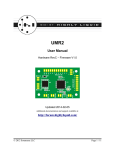
Highly Liquid
MSA Firmware V. 3.1
MSA
Firmware Version 3.1
User Manual
Updated 2010-12-09
Additional documentation available at:
http://highlyliquid.com/support/
© 2010 Sonarcana LLC
Page 1 / 14
Highly Liquid
MSA Firmware V. 3.1
Table of Contents
1.0 Overview..............................................................................................................3
1.1 About The MSA....................................................................................................................3
1.2 About This Document............................................................................................................3
1.3 Additional Resources.............................................................................................................3
2.0 Individual Output Operation..................................................................................4
2.1 Learn Method.......................................................................................................................4
2.2 SysEx Method.......................................................................................................................5
2.2.1 Output Mode (mm) and Data (d0, d1).......................................................................................................5
2.2.2 Pulse Length (ph, pl)..................................................................................................................................5
3.0 Preset Operation...................................................................................................7
3.1 Learn Method.......................................................................................................................7
3.2 SysEx Method.......................................................................................................................8
3.2.1 Recall Type (rr)..........................................................................................................................................8
3.2.2 Preset State (nn, s0-s7)...............................................................................................................................8
4.0 Factory Default Configuration...............................................................................9
5.0 Configuration Retrieval.......................................................................................10
5.1 Identity Request / Identity Reply.........................................................................................10
5.2 Output Configuration Retrieval..........................................................................................11
6.0 DIP Switch..........................................................................................................12
6.1 MIDI Channel.....................................................................................................................12
6.2 Unit ID................................................................................................................................12
7.0 Activity LED.......................................................................................................13
8.0 Firmware Update................................................................................................14
8.1 Firmware Update Procedure...............................................................................................14
8.2 Notes...................................................................................................................................14
© 2010 Sonarcana LLC
Page 2 / 14
Highly Liquid
MSA Firmware V. 3.1
1.0 Overview
Users are encouraged to read MSA Hardware User Manual before continuing with this document.
1.1 About The MSA
The MSA is a multipurpose MIDI decoder. It can activate its 8 outputs in response to incoming MIDI
messages of virtually any type.
The MSA has two basic types of operation. At any time, the MSA can be configured for only one of the
following:
•
Individual Output Operation: Each MSA output responds independently to MIDI input.
•
Preset Operation: The MSA stores up to 128 “presets”, each consisting of an 8-output state.
Presets are recalled using program change, CC, or note commands.
To specify the desired behavior for either of the above operation types, the user can employ one of two
configuration methods:
•
“Learn” Method: MSA behavior is specified via a mixture of switch input and MIDI messages.
•
SysEx Method: MIDI System Exclusive (SysEx) messages are used to specify MSA behavior.
MSA configuration is retained when the MSA is disconnected from a power supply.
The MSA ships with a “factory default” configuration which can be described in terms of equivalent
SysEx messages. See Factory Default Configuration.
1.2 About This Document
Throughout this document, SysEx message contents are shown in hexadecimal format. Hexadecimal
numbers either are described as “hex” or are followed by the 'h' suffix. Decimal format should be
assumed for all other numbers.
Sections of the manual that have changed significantly since the previous firmware version are
highlighted in yellow.
1.3 Additional Resources
Instructions for using a PC to create and send SysEx messages can be found at:
http://highlyliquid.com/support/library/midi-sysex.html
Support inquiries should be posted at the Highly Liquid support forums. Project examples and other
information are posted at the forums:
http://forum.highlyliquid.com/
© 2010 Sonarcana LLC
Page 3 / 14
Highly Liquid
MSA Firmware V. 3.1
2.0 Individual Output Operation
When the MSA is configured for Individual Output Operation, each MSA output responds independently
to a specific MIDI message. Configure the MIDI response of each output via the Learn Method or SysEx
Method.
2.1 Learn Method
A user-supplied “program” (PRGM) switch must be attached to the MSA “PRGM” terminals. If no
switch is available, a piece of wire can be used to temporarily connect the terminals. See MSA Hardware
User Manual for wiring details.
Use the following procedure to configure the MSA:
1. Set the MSA DIP Switch for the desired MIDI channel.
2. Connect power to the MSA while pressing the PRGM switch.
3. Release the PRGM switch. The activity LED will blink slowly to indicate that the MSA is ready
to learn.
4. Send a series of 8 MIDI messages to the MSA MIDI In port. As each message is received, the
MSA output being assigned to the message will temporarily activate. Allow each output to
deactivate before proceeding with the next message.
5. After the 8th message is received, the configuration is stored. To resume normal operation,
disconnect, then reconnect power to the MSA.
Table 2-a shows the MIDI message types that can be learned. A single message type or a mixture of
message types can be used. If different output modes are desired, the SysEx Method method must be
used.
Table 2-a: Output Configuration by Message Type
MIDI Message
Type
Resulting Configuration
Note
Note Trigger
CC
CC On/Off
Program Change
Program Change “Match Only”
If the MSA does not receive 8 qualifying messages, any partially learned configuration will be discarded,
and the prior configuration will remain.
The learn method can be repeated as desired to change the MSA configuration. Configuration is retained
when the MSA is disconnected from a power supply.
© 2010 Sonarcana LLC
Page 4 / 14
Highly Liquid
MSA Firmware V. 3.1
2.2 SysEx Method
Figure 2-1 shows the format of the Individual Output Configuration SysEx Message. The message is a
string of exactly 34 bytes. The body of the message consists of a Unit ID, a 3-byte configuration for each
of the 8 MSA outputs, and a 2-byte pulse length.
Upon success, the MSA activity LED blinks 3 times and Individual Output Operation begins.
Figure 2-1: Individual Output Configuration SysEx Message
Section
Format (Hex)
Fixed Header
F0 00 01 5D 05 01
Unit ID
id
Output 0 Configuration
mm d0 d1
Output 1 Configuration
mm d0 d1
Output 2 Configuration
mm d0 d1
Output 3 Configuration
mm d0 d1
Output 4 Configuration
mm d0 d1
Output 5 Configuration
mm d0 d1
Output 6 Configuration
mm d0 d1
Output 7 Configuration
mm d0 d1
Pulse Length
ph pl
Fixed Footer
F7
2.2.1 Output Mode (mm) and Data (d0, d1)
Parameter mm specifies the output mode for the corresponding MSA output. For “normal” modes, the
output is “off” by default and is activated in response to incoming MIDI events. For “inverted” modes,
the output is “on” by default with an inverted MIDI response.
The meaning of bytes d0 and d1 depend on the value of mm.
Output modes are described in Table 2-b.
2.2.2 Pulse Length (ph, pl)
Certain output modes generate fixed-length output pulses. The length of the output pulse is set “globally”
via the values ph and pl, according to the following formula:
pulse length = ((ph × 128) + pl + 1) × 0.5 ms
The valid range for both ph and pl is 00h–7Fh. Thus, the maximum configurable pulse length is
approximately 8.2 seconds. Actual pulse length is accurate to 0.5 ms of configured value.
Output modes which do not generate fixed-length pulses are not affected by the values ph and pl.
© 2010 Sonarcana LLC
Page 5 / 14
Highly Liquid
MSA Firmware V. 3.1
Table 2-b: Output Modes
mm (Hex)
Mode Description
d0 Meaning
d1 Meaning
Ignored
Ignored
Note Trigger
Output is “on” for the duration of the corresponding
MIDI note with velocity greater than or equal to d1.
Note Number
Velocity
Threshold
42
Note Trigger – Fixed Length Pulse
Matching note on messages with a velocity equal to or
greater than d1generate a pulse with length determined
by the values of ph and pl.
Note Number
Velocity
Threshold
43
Note Toggle
Output state is toggled & latched upon the receipt of a
matching Note On message.
Note Number
Velocity
Threshold
48
CC On/Off
Matching CC messages with a value equal to or
greater than d1 latch output “on”. Matching CC
messages with a value less than d1 latch output “off”.
CC Number
Value
Threshold
49
CC – Fixed Length Pulse
Matching CC messages with a value equal to or
greater than d1generate a pulse with length determined
by the values of ph and pl.
CC Number
Value
Threshold
0A
4A
CC Toggle
Output is toggled & latched upon the receipt of
matching CC messages with a value equal to or greater
than d1.
CC Number
Value
Threshold
0B
4B
CC “Match Only”
Output is latched “on” when a matching CC message
is received. All other CC messages latch output “off”.
CC Number
Ignored
10
50
Program Change “Match Only”
Output is latched “on” when a matching program
change message is received. All other program change
messages latch output “off”.
Program
Number
Ignored
11
51
Program Change – Fixed Length Pulse
Matching program change messages generate a pulse
with length determined by the values ph and pl.
Program
Number
Ignored
18
58
Sync – Run
Output is latched “on” by MIDI Start or MIDI
Continue messages, and is latched “off” by MIDI Stop
messages.
Ignored
Ignored
19
59
Sync – Clock
MIDI Clock messages generate pulses with length
determined by ph and pl.
Ignored
Ignored
Normal
Inverted
00
40
Disabled
Output does not respond to MIDI input.
01
41
02
03
08
09
© 2010 Sonarcana LLC
Page 6 / 14
Highly Liquid
MSA Firmware V. 3.1
3.0 Preset Operation
The MSA stores up to 128 “presets”, each consisting of an 8-output state. Presets are recalled using
program change, CC, or note commands. Configure the MIDI response of each output via the Learn
Method or SysEx Method.
3.1 Learn Method
A user-supplied “program” (PRGM) switch must be attached to the MSA “PRGM” terminals. If no
switch is available, a piece of wire can be used to temporarily connect the terminals. See MSA Hardware
User Manual for wiring details.
Use the following procedure to configure the MSA:
1. Connect power to the MSA. Allow the activity LED self-test to complete.
2. Press, then release the PRGM switch. The activity LED will blink twice to indicate that the MSA
is ready to learn.
3. While learning, the MSA will listen for MIDI Program Change, CC, and Note messages on all
channels.
4. Send the MSA a MIDI message corresponding to the preset to be learned. The MSA outputs will
be updated to reflect the existing preset state.
5. Set DIP switch positions 1-4 to correspond to the desired MSA output states 0-3 for this preset.
6. Press and release the PRGM switch. The MSA will set outputs 0-3 as directed in step 5.
7. Set the DIP switch positions 1-4 to correspond to the desired MSA output states 4-7 for this
preset.
8. Press and release the PRGM switch. The MSA will set all outputs as directed in steps 5 and 7,
and store the output state to the selected preset.
9. Repeat steps 4-8 as desired.
10. To resume normal operation, disconnect, then reconnect power to the MSA.
Important Notes:
1. During normal operation, the MSA will respond only to MIDI messages on the channel specified by the
DIP Switch. Be sure to return the DIP switch to the desired channel setting after the learn procedure.
2. The MSA will remember the message type (Program Change, CC, or Note) used during the learning
process. The same message type must be used to recall presets during normal operation.
© 2010 Sonarcana LLC
Page 7 / 14
Highly Liquid
MSA Firmware V. 3.1
3.2 SysEx Method
Figure 3-1 shows the format of the Preset Configuration SysEx Message. The message consists of a
fixed header, Unit ID, and recall type, followed by one or more 9-byte preset states.
Upon success, the MSA activity LED blinks 3 times and Preset Operation begins.
Figure 3-1: Preset Configuration SysEx Message
Section
Format (Hex)
Fixed Header
F0 00 01 5D 05 02
Unit ID
id
Recall Type
rr
Preset State
nn s0 s1 s2 s3 s4 s5 s6 s7
Preset State (Optional)
nn s0 s1 s2 s3 s4 s5 s6 s7
Preset State (Optional)
nn s0 s1 s2 s3 s4 s5 s6 s7
.
.
.
.
.
.
Preset State (Optional)
nn s0 s1 s2 s3 s4 s5 s6 s7
Fixed Footer
F7
3.2.1 Recall Type (rr)
Byte rr specifies which type of MIDI message will be used to recall the presets during operation. See
Table 3-a.
Table 3-a: Recall Types
rr (Hex)
Recall Type
01
Program Change
02
CC
04
Note
3.2.2 Preset State (nn, s0-s7)
Byte nn specifies the number of the preset defined by the following 8 bytes. nn corresponds to the MIDI
program, CC, or note number used to recall the preset. The MSA can store up to 128 presets. The valid
range for nn is 00h-7Fh.
Byte s0-s7 specify the states of MSA outputs 0-7. For these bytes, a value of 00h sets the output to off,
and a value of 01h sets the value to on.
© 2010 Sonarcana LLC
Page 8 / 14
Highly Liquid
MSA Firmware V. 3.1
4.0 Factory Default Configuration
By default, the MSA operates in Individual Output Operation. MSA outputs 0-7 respond to MIDI notes
60-67. The default configuration can be described by an Independent Output Configuration SysEx
Message as shown in Figure 4-1.
Figure 4-1: Factory Default Configuration SysEx Message
SysEx Data (Hex)
Meaning
F0 00 01 5D 05 01
Fixed header
00
Unit ID (00h = All Units)
01 3C 01
Output 0 configuration
01 3D 01
Output 1 configuration
01 3E 01
Output 2 configuration
01 3F 01
Output 3 configuration
01 40 01
Output 4 configuration
01 41 01
Output 5 configuration
01 42 01
Output 6 configuration
01 43 01
Output 7 configuration
07 67
F7
© 2010 Sonarcana LLC
Pulse length: 500ms
(Not used by factory default output modes.)
Fixed Footer
Page 9 / 14
Highly Liquid
MSA Firmware V. 3.1
5.0 Configuration Retrieval
5.1 Identity Request / Identity Reply
The MSA responds to the standard “Identity Request” SysEx command. If the MSA receives the SysEx
message described in Figure 5-1, it will respond with the standard “Identity Reply” message described in
Figure 5-2.
Figure 5-1: Identity Request SysEx Message
SysEx Data (Hex)
Meaning
F0 7E 7F 06 01 F7
Fixed Message
Figure 5-2: Identity Reply SysEx Message
SysEx Data (Hex)
Meaning
F0 7E 7F 06 02
Fixed Header
00 01 5D
Manufacturer ID
00 00
Family Code (MIDI Decoder)
00 05
Model (MSA Rev K)
00 vv
Version, where vv is the firmware version number
as described in Table 5-a.
id
Unit ID
tt
Configured Operation Type. tt = 01h for
Individual Output Operation. tt = 02h for Preset
Operation.
F7
Fixed Footer
Table 5-a: Firmware Version
© 2010 Sonarcana LLC
vv (Hex)
Firmware Version
00
3.0
01
3.1
02 thru 7F
Reserved for future
versions.
Page 10 / 14
Highly Liquid
MSA Firmware V. 3.1
5.2 Output Configuration Retrieval
The current MSA configuration can be retrieved via the MSA MIDI Out port.
If the MSA receives a SysEx message as described in Figure 5-3, it will send its configuration as an
Individual Output Configuration SysEx Message.
If the MSA receives a SysEx message as described in Figure 5-4 or Figure 5-5, it will send its
configuration as a Preset Configuration SysEx Message.
Figure 5-3: Individual Output Configuration Request SysEx Message
SysEx Data (Hex)
Meaning
F0 00 01 5D 05 00 00 01 F7 Fixed Message
Figure 5-4: Preset Request (Single Preset) SysEx Message
SysEx Data (Hex)
F0 00 01 5D 05 00 00 02
Meaning
Fixed Header
pp
Preset #
F7
Fixed Footer
Figure 5-5: Preset Request (128-Preset Dump) SysEx Message
SysEx Data (Hex)
Meaning
F0 00 01 5D 05 00 00 04 F7 Fixed Message
© 2010 Sonarcana LLC
Page 11 / 14
Highly Liquid
MSA Firmware V. 3.1
6.0 DIP Switch
The MSA DIP switch serves two main purposes: to set the MIDI channel for MIDI input, and to set the
“Unit ID”. See Table 6-a.
6.1 MIDI Channel
The MSA DIP switch is used to specify the MIDI channel for incoming MIDI messages. During normal
operation, the MSA will respond only to messages received on this channel.
6.2 Unit ID
Each configuration SysEx message contains a Unit ID byte.
If the Unit ID byte is 00h, any MSA unit receiving the message will configure itself as directed by the
message.
If the Unit ID byte is between 1 and 16 (01h to 10h), any MSA receiving the message will update its
configuration only if its DIP Switch setting matches the Unit ID. This allows the user to target &
configure a single MSA within a chain of multiple units.
Table 6-a: MIDI Channel / Unit ID DIP Switch Settings
© 2010 Sonarcana LLC
MIDI
Channel /
Unit ID
SW1 Setting
1
2
3
4
1
off
off
off
off
2
off
off
off
on
3
off
off
on
off
4
off
off
on
on
5
off
on
off
off
6
off
on
off
on
7
off
on
on
off
8
off
on
on
on
9
on
off
off
off
10
on
off
off
on
11
on
off
on
off
12
on
off
on
on
13
on
on
off
off
14
on
on
off
on
15
on
on
on
off
16
on
on
on
on
Page 12 / 14
Highly Liquid
MSA Firmware V. 3.1
7.0 Activity LED
The MSA activity LED performs several functions:
●
Self Test: Upon power-up or device reset, the activity LED lights briefly before normal operation
begins.
●
Configuration Update Indication: When the MSA configuration is updated via a MIDI SysEx
message, the MSA will reset, followed by the LED self-test. If no LED activity is observed, then
the attempted configuration was unsuccessful.
●
MIDI Activity Indication: The LED blinks when a MIDI message is received that affects the
MSA output state. Other MIDI messages will not cause an activity indication.
●
Learn Mode Indication: The LED will blink slowly while the MSA awaits MIDI messages
during Learn Mode.
●
Firmware Update Error: The LED blinks continuously when the receipt of a firmware update
SysEx message has failed, or when the firmware has become corrupt.
© 2010 Sonarcana LLC
Page 13 / 14
Highly Liquid
MSA Firmware V. 3.1
8.0 Firmware Update
MSA firmware can be upgraded via MIDI SysEx message. Firmware update files, when available, can be
downloaded from the MSA product page at highlyliquid.com.
8.1 Firmware Update Procedure
1. Download and unzip the firmware update SysEx message. The resulting file should have the
extension “.syx”.
2. Disconnect power to the MSA.
3. Press and hold the PRGM switch. (See MSA Hardware User Manual.)
4. Reconnect power to the MSA. The activity LED will remain lighted.
5. Send the firmware update SysEx message to the MSA. Transmission of the message may require
several seconds.
6. Upon completion of the update, the activity LED will deactivate.
7. Release the PRGM switch.
8. Disconnect power to the MSA.
8.2 Notes
•
Do not interrupt the transmission of the firmware update SysEx message.
•
A continuously blinking activity LED indicates an error in the transmission of the firmware
update SysEx message.
•
If a continuously blinking activity LED is observed, repeat the procedure from the beginning.
•
The current firmware version can be retrieved via Identity Request / Identity Reply SysEx
messages.
© 2010 Sonarcana LLC
Page 14 / 14