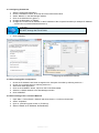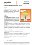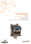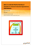
1
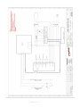
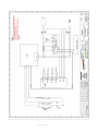
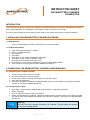
ABCM BATTERY CHARGER User Manual Revision: 3 – May 2014 Designed and manufactured in Australia by Ampcontrol Electronics Pty Ltd A Ampcontrol Electronics Pty Ltd – ABN 35 000 770 141 ABCM Battery Charger User Manual Rev 3 – 05/14 WARNING! CAUTION! This safety alert symbol identifies important safety messages in this manual and indicates a potential risk of injury or even death to personnel. When you see this symbol, be alert, your safety is involved, carefully read the message that follows, and inform other operators. This safety alert symbol identifies important information to be read in order to ensure the correct sequence of work and to avoid damage or even destruction of the equipment, and reduce any potential risk of injury or death to personnel. Supplementary information not directly affecting safety or damage to equipment. Carefully read the message that follows, and inform other relevant personnel. Information concerning possible impact on the environment and actions required for prevention and proper response. ABCM CHARGER USER MANUAL 22/08/2014 15:11 Page 2 of 19 Ampcontrol Electronics Pty Ltd – ABN 35 000 770 141 ABCM Battery Charger User Manual Rev 3 – 05/14 Copyright Notice The Ampcontrol ABCM Battery Charger described in this document is the property of AMPCONTROL PTY LTD. It is furnished under a license agreement and is to be used only in accordance with the terms of the agreement. No part of the hardware or documentation may be reproduced, transmitted, transcribed, stored in a retrieval system, or translated into any language or computer language, in any form or by any means, without prior written permission of AMPCONTROL PTY LTD. Disclaimer While every effort has been made to assure the accuracy and clarity of this document, AMPCONTROL PTY LTD assumes no liability resulting from any omissions in this document, or from misuse of the information obtained herein. The information in this document has been carefully checked and is believed to be entirely reliable with all of the necessary information included. AMPCONTROL PTY LTD reserves the right to make changes to any products described herein to improve reliability, function, or design, and reserves the right to revise this document and make changes from time to time in content hereof with no obligation to notify any persons of revisions or changes. AMPCONTROL PTY LTD does not assume any liability arising out of the application or any use of any product or circuit described herein; neither does it convey license under its patent rights or the rights of others. Before You Begin We would like to take a moment to thank you for purchasing the Ampcontrol ABCM Battery Charger. WARNING! To become completely familiar with this equipment and to ensure correct operation, we strongly recommend that you take the time to read and thoroughly understand this user manual. Ampcontrol Electronics Contact Details 7 Billbrooke Close, Cameron Park, NSW, 2285 P +61 2 4903 4800 | F +61 2 4903 4888 EMAIL: [email protected] WEB: www.ampcontrolgroup.com ABCM CHARGER USER MANUAL 22/08/2014 15:11 Page 3 of 19 Ampcontrol Electronics Pty Ltd – ABN 35 000 770 141 ABCM Battery Charger User Manual Rev 3 – 05/14 TABLE OF CONTENTS 1 SAFETY AND OTHER WARNINGS ................................................................... 5 1.1 Safe Use of Equipment ............................................................................... 5 2 RECEIVING AND STORAGE ............................................................................. 7 2.1 Receiving ..................................................................................................... 7 2.2 Inspection .................................................................................................... 7 2.3 Storage after Delivery .................................................................................. 7 2.4 Unpacking of Equipment ............................................................................. 7 2.5 Storage and Care of Batteries ..................................................................... 8 3 INSTALLATION................................................................................................... 9 3.1 General Warnings ....................................................................................... 9 3.2 Mandatory Installation Practices ................................................................. 9 4 ABCM BATTERY CHARGER OVERVIEW ....................................................... 10 4.1 Mechanical Arrangement .......................................................................... 11 4.2 Electrical Connections ............................................................................... 11 4.3 System Description ................................................................................... 12 4.4 System Components ................................................................................. 12 5 COMMISSIONING AND CALIBRATION........................................................... 13 6 OPERATION SUMMARY.................................................................................. 14 6.1 Display ....................................................................................................... 14 6.2 Indication LEDs ......................................................................................... 15 6.3 Settings and Calibration ............................................................................ 15 6.4 Alarms ....................................................................................................... 16 7 TROUBLESHOOTING ...................................................................................... 17 8 SERVICE, MAINTENANCE & DISPOSAL ........................................................ 18 8.1 Equipment Service .................................................................................... 18 8.2 Equipment Maintenance ............................................................................ 18 8.3 Disposal ..................................................................................................... 18 9 SPECIFICATIONS ............................................................................................ 19 10 EQUIPMENT LIST .......................................................................................... 19 APPENDIX A - DRAWINGS………………………………………………………….. A APPENDIX B – CHARGER CONNECTIONS INSTRUCTIONS………………….. B ABCM CHARGER USER MANUAL 22/08/2014 15:11 Page 4 of 19 Ampcontrol Electronics Pty Ltd – ABN 35 000 770 141 ABCM Battery Charger User Manual Rev 3 – 05/14 1 SAFETY AND OTHER WARNINGS For safety reasons, the ABCM Battery Charger must be installed, operated and serviced only by competent personnel. Read and understand this instruction manual completely before installing, operating or servicing this equipment. Failure to install or operate this instrument in accordance with the instructions contained in this manual may create hazardous operating conditions. 1.1 Safe Use of Equipment The equipment supplied has been manufactured according to the state of the art, and designed to ensure a safe operation. The equipment may only be used within the design parameters. If there are any signs of modification or damage to this equipment, it must not be used until it has been repaired and deemed fit for purpose by the equipment’s manufacturer or by an AS/NZS 3800 accredited workshop. The instructions within this manual must be observed as an aid towards achieving maximum safety during operation. The owner/user is responsible for observing the following instructions: 1.1.1 Changes to Equipment Changes in the design and modifications to the equipment are not permitted. Unauthorised changes made to the hardware or operating firmware will void the manufacturer's warranty, and may compromise the integrity of the system into which it is installed and other connected equipment. 1.1.2 Equipment Knowledge Experience with, or understanding of, this equipment is essential for the safe installation and removal of the equipment. Therefore, in case of a question on how to safely proceed, contact Ampcontrol immediately. 1.1.3 Manual Handling Precautions have been taken to ensure all equipment is safe to handle and free from sharp edges. However care should always be taken when handling enclosures and gloves should be worn. 1.1.4 Installation Correct operation and safety depend on the ABCM Battery Charger and associated equipment being installed correctly. Mechanical and or electrical installation and maintenance of plant and equipment must only be carried out by appropriately qualified personnel and must be tested thoroughly prior to operation. Mechanical Installation – After unpacking the crates and packages the battery charger must be transported using appropriate lifting equipment to the intended installation area. The battery charger may be supplied with or without the batteries and enclosure/s (depending on the client purchase order) but these mechanical installation instructions should still serve as a general guide. WARNING! The lower cabinet must be firmly secured to the ground or its support structure, and the upper cabinet must be firmly attached to the lower cabinet using appropriate fasteners. This is essential to maintain the structural integrity of the assembled cabinets. ABCM CHARGER USER MANUAL 22/08/2014 15:11 Page 5 of 19 Ampcontrol Electronics Pty Ltd – ABN 35 000 770 141 ABCM Battery Charger User Manual Rev 3 – 05/14 When the cabinet is correctly positioned, such that the incoming and outgoing cables are not impeded in any way and adequate personnel and maintenance clearance is available around the cabinet (including any statutory allowance for when the doors are open) the cabinet must be bolted to the ground. Electrical Installation - After the termination of incoming cables (including earth) and the outgoing cables to the appropriate terminals, check all cable connections for tightness including the interconnection of the cables between printed circuit boards. During shipment the positive terminal(s) of the included batteries have been insulated and disconnected from the battery terminal(s) for safety reasons – reconnect these terminals with care. The batteries are delivered filled, charged and ready for connection. No operation such as filling, commissioning or other type is required. They need only be connected as required by the particular application. If the batteries were delivered separately from the cabinet install them in the cabinet starting from the lowest level first to ensure stability. 1.1.5 Operation The ABCM Battery Charger is intended to be used as part of the overall power system operating in the mining environment. It provides back-up power to control systems to increase system reliability and safety. The battery charger system is not intended to be the sole method of providing control system power to the mining environment. Other methods should be employed to ensure the highest level of system integrity and reliability. As safety depends on the ABCM Battery Charger functioning correctly, it is highly recommended that all safety functions of the charger be periodically tested to ensure correct operation. ABCM CHARGER USER MANUAL 22/08/2014 15:11 Page 6 of 19 Ampcontrol Electronics Pty Ltd – ABN 35 000 770 141 ABCM Battery Charger User Manual Rev 3 – 05/14 2 RECEIVING AND STORAGE 2.1 Receiving All possible precautions are taken to protect the equipment against damage or losses during shipment, however before accepting delivery, check all items against the packing list or bill of loading. If there are shortages or evidence of physical damage, notify Ampcontrol immediately. Notify Ampcontrol within 7 days (maximum) in case of shortages or discrepancies, according to the packing list. This action will help ensure a speedy resolution to any perceived problems. Keep a record of all claims and correspondence. Photographs are recommended. Where practicable do not remove protective covers prior to installation unless there are indications of damage. Boxes opened for inspection and inventory should be carefully repacked to ensure protection of the contents or else the parts should be packaged and stored in a safe place. Examine all packing boxes, wrappings and covers for items attached to them, especially if the wrappings are to be discarded. 2.2 Inspection Equipment that is found to be damaged or has been modified away from its published specification must not be used. Please contact Ampcontrol if the equipment is suspected to be different than that ordered or if it does not match the published specifications. 2.3 Storage after Delivery Where equipment is not to be installed immediately, proper storage is important to ensure protection of equipment and validity of warranty. All equipment should be stored indoors protected from the elements in a cool dry area. If storing on the ground, ensure that the storage area is not an area where water will collect. When applicable, the correct handling and fork lift procedures must be in place to ensure that any crates and pallets are moved safely. 2.4 Unpacking of Equipment The method of packing used will depend on the size and quantity of the equipment. The following cautions should be interpreted as appropriate. CAUTION! Take care when unpacking crates as the contents may have shifted during transport. The disposal of packaging materials, replaced parts, or components must comply with environmental restrictions without polluting the soil, air or water. Ensure that any timber and cardboard used as packaging is disposed of in a safe and environmentally responsible manner. Where possible, dispose of all waste products i.e. oils, metals, plastic and rubber products by using an approved recycling service centre. ABCM CHARGER USER MANUAL 22/08/2014 15:11 Page 7 of 19 Ampcontrol Electronics Pty Ltd – ABN 35 000 770 141 ABCM Battery Charger User Manual Rev 3 – 05/14 2.5 Storage and Care of Batteries The batteries are delivered filled, charged and ready for connection. It is recommended that the storage period of the batteries be as short as possible. The temperature of the environment in which the batteries are stored has an impact on the discharge rate of the units and hence it is important to store the batteries in a fully charged condition in a cool, dry environment. The batteries will come already installed in the battery cabinet for smaller assemblies but could be shipped separately for larger units. If batteries are received already installed, ensure that the positive cable remains in the same way at it is shipped, that is, disconnected and insulated. CAUTION! Open circuit batteries lose part of their capacity due to self-discharge (2% per month at 20°C). A float recharge at least every six months (applying a voltage of 2.27V/cell for approximately 48 hours) is recommended to maintain battery life. ABCM CHARGER USER MANUAL 22/08/2014 15:11 Page 8 of 19 Ampcontrol Electronics Pty Ltd – ABN 35 000 770 141 ABCM Battery Charger User Manual Rev 3 – 05/14 3 INSTALLATION 3.1 General Warnings These instructions have been designed to assist users of the ABCM Battery Charger with installation. Before the ABCM can be installed, there are a number of things that need to be considered and understood to prevent incorrect or unsafe operation of the battery charger or the system into which it is installed. Along with relevant competence, and an understanding of the target application, the following points should be considered: 3.1.1 Ensure that the information provided in this user manual is fully understood. It is extremely important that the limitations and functionality of the ABCM Battery Charger are understood to prevent incorrect installation and use from creating a potentially dangerous risk. If in doubt as to the nature of the limitations or their implication, consult a competent authority such as a supervisor or Ampcontrol technical representative. 3.1.2 Ensure that the application into which the ABCM Battery Charger is being installed has been properly defined, designed and approved. Any system intended to mitigate the risk of injury needs to be properly designed and implemented. Such a system must be the result of structured risk analysis with the outcomes used to define the system requirements. These requirements, in turn, will guide the choice of instrumentation, logic solvers and actuators needed to implement the system. Understanding the needs of the system will ensure proper selection of equipment. 3.1.3 Ensure that the ABCM Battery Charger will properly perform the required functions within the system design. It is important to understand how the battery charger is intended to interact with other equipment within a system. For safe and reliable use, it is crucial that neither the charger’s logical operation nor its signalling be compromised by incompatibilities with connected equipment. 3.1.4 Modifications of any form to the ABCM Battery Charger are prohibited. The ABCM as supplied has been designed and manufactured to comply with the requirements of protection standards. If modifications of any form are made to the battery charger, the equipment may no longer be fit for use. If any modifications or damage to the charger is evident, do not use the equipment and contact Ampcontrol for advice. 3.2 Mandatory Installation Practices The following information must be adhered to when installing the ABCM Battery Charger. Failure to adhere to this information may give rise to unsafe operation. Using the ABCM in a manner that exceeds its electrical, functional or physical specifications, or in a way that is contrary to its operating restrictions, may create risks to personnel and/or equipment resulting in injury or death. The charger must be powered within the specified voltage range. The installation of the battery charger must be carried out by suitably trained and qualified personnel. Identification labels fixed to the ABCM must not be damaged, removed or covered before, during or after installation. The installation is to be in accordance with the relevant installation Standards/Codes of Practice. Modifications must not be made to any part of the battery charger. As supplied, the unit is built to, and complies with the relevant standards. Modification to its construction will render the unit noncompliant. Complete and accurate records of the installation must be kept as part of the site installation. ABCM CHARGER USER MANUAL 22/08/2014 15:11 Page 9 of 19 Ampcontrol Electronics Pty Ltd – ABN 35 000 770 141 ABCM Battery Charger User Manual Rev 3 – 05/14 4 ABCM BATTERY CHARGER OVERVIEW The Ampcontrol ABCM Single Phase Battery Charger uses a microprocessor to control a switched mode rectifier unit. This produces a highly stable output voltage which is designed to maintain the charge of stand-by batteries, where a constant voltage and current limiting is desired. The battery charger may be used, for example, to provide back-up power for control voltage applications and for emergency lighting. Battery charging is achieved through manual, automatic and interval boost charge modes, and boost voltages can be adjusted to ensure optimum charging times whilst preserving battery life. A high resolution colour display allows for local communication for metering, alarm messages and to allow for parameter configuration. The charger also includes Ethernet connectivity which allows for monitoring of system status remotely via a web browser or PC program. LEDs are also installed on the display unit to provide indication of local alarms. Comprehensive logging of system status allows trending of data to increase system efficiency. Key Features Modular design Ethernet connectivity for local or remote monitoring Manual, automatic and interval Boost charge modes High resolution colour display for metering, alarm messages and parameter configuration. LEDs for local visual alarms Comprehensive logging SD Card slot for setup and downloading event logs Applicable Standards The following standards are referenced for the manufacture of the battery charger: AS/NZS 3000:2007 Electrical Installations AS/NZS 3350.2.29:1996 Safety of Household and Similar Electrical Appliances - Particular Requirements-Battery Chargers. ASNZS 3100:2009 Approval and Test Specification - General Requirements for Electrical Equipment. AS/NZS 4044 –1992 (battery chargers for stationary batteries) Other referenced standards are as follows: EN55022 (EMI Conduction & Radiation) EN61000-3-2, -3 (Harmonic Current) EN61000-4-2, -3, -4, -5, -6, -8 (EMS (Noise) Immunity) Electrical Safety: a. IEC 60950-1 b. UL 60950-1 c. CSA 22.2 EMC: a. ETSI EN 300 386 V1.3.2 b. EN 61000-6-1 (immunity, light industry) c. EN 61000-6-2 (immunity, industry) d. EN 61000-6-3 (emission, light industry) e. EN 61000-6-4 (emission, industry) Environment: a. ETSI EN300 019-2-1 Class 1.2 b. ETSI EN 300 019-2-2 Class 2.3 c. ETSI EN 300 019-2-3 Class 3.2 d. ETSI EN 300 132-2 e. RoHS Compliant ABCM CHARGER USER MANUAL 22/08/2014 15:11 Page 10 of 19 Ampcontrol Electronics Pty Ltd – ABN 35 000 770 141 ABCM Battery Charger User Manual Rev 3 – 05/14 4.1 Mechanical Arrangement 4.1.1 Enclosure The ABCM Battery Charger can be supplied on a standard pan for installation in an existing enclosure, or supplied in a mild steel or stainless enclosure to suit application. The enclosure is rated IP20. The ABCM Battery Charger enclosure includes the battery charger modules and shelving to store batteries. An example of the arrangement and size of two types of battery charger enclosure is shown in Figure 1. Section 9: Specifications, outlines the dimensions of all typical ABCM Battery Charger enclosures. Figure 1: ABCM battery charger enclosure: larger (left) and smaller (right) 4.2 Electrical Connections Once the ABCM Battery Charger has been installed in a suitable location, it is necessary to wire it correctly. Appendix A shows a typical wiring diagram for the application of the ABCM Battery Charger. ABCM CHARGER USER MANUAL 22/08/2014 15:11 Page 11 of 19 Ampcontrol Electronics Pty Ltd – ABN 35 000 770 141 ABCM Battery Charger User Manual Rev 3 – 05/14 4.3 System Description The ABCM Battery Charger assembly comprises of an Eltek controller, rectifier, and input and output monitoring and control for interface circuits and batteries. The batteries are charged at a constant voltage level with current limiting. The constant voltage, boost voltage and current limit can be set to ensure optimum charging times whilst preserving battery life. The controller consists of Master and Basic units. The Basic unit provides control and monitoring of the internal system functionality. The Master unit provides a graphical user interface which allows access to voltage and current measurements and system alarms and faults. Remote access to functions and parameters is provided via a standard web browser, or using a PC application via SD card or Ethernet connection. The rectifier controls the DC output voltage, providing a fully regulated output. The charger includes protection for over and under voltage, earth fault, short circuit and over temperature. Figure 2 details a block diagram of the charger network. Ethernet Display Web User Interface Eltek Controller IO Monitoring and Control Mains Power Rectifier Charger Load Battery Bank Figure 2: ABCM Battery Charger network block diagram 4.4 System Components The ABCM Battery Charger utilises third party components to provide control and monitoring of the charger operation. 4.4.1 Controller Unit The controller unit provides the user with a high resolution display for system status and parameter and event information. Indication LEDs also provide feedback on alarms locally. The controller also provides programmable inputs and outputs for remote monitoring system parameters. 4.4.2 Rectifier The rectifier controls the DC output voltage, providing a fully regulated output. The charger includes protection for over and under voltage, earth fault, short circuit and over temperature. 4.4.3 Batteries The batteries are charged at a constant voltage level with current limiting. In Boost Mode, the charging current does not change, but the voltage is increased in value. The constant voltage, boost voltage and current limit can be set to ensure optimum charging times whilst preserving battery life. ABCM CHARGER USER MANUAL 22/08/2014 15:11 Page 12 of 19 Ampcontrol Electronics Pty Ltd – ABN 35 000 770 141 ABCM Battery Charger User Manual Rev 3 – 05/14 5 COMMISSIONING AND CALIBRATION Prior to being put into service, the electrical protection system must be correctly commissioned. This manual does not cover system commissioning; the full scope of commissioning tests should be determined during the risk assessment or FMEA covering the design of the electrical protection system. The following test can provide guidance on checking the correct operation of the ABCM Battery Charger during commissioning. This is not intended to provide an exhaustive commissioning checklist, but should be considered to be a minimum set of tests. 5.1.1 Commissioning 1. Open all circuit breakers 2. Turn on DC power supply and close battery circuit breaker. 3. The controller should now power up and the high resolution display will show the Status Mode screen. 4. Close the AC input power circuit breaker. 5. This will activate the rectifier system and start to charge the battery in ‘Float’ mode. 6. At this stage there should be a fault alarm shown on the display. 7. Turn on the load circuit breakers as required. 8. The alarm should no longer be showing on the display panel. 9. The charger will now start supplying the loads and charging the battery bank/s. 10. The Status screen will display the battery voltage and current, load current and battery temperature, if enabled and valid. 11. The ABCM Battery Charger should begin to top up the batteries. ABCM CHARGER USER MANUAL 22/08/2014 15:11 Page 13 of 19 Ampcontrol Electronics Pty Ltd – ABN 35 000 770 141 ABCM Battery Charger User Manual Rev 3 – 05/14 6 OPERATION SUMMARY 6.1 Display The ABCM Battery Charger displays user information locally via a TFT high contrast, high resolution colour display. 6.1.1 Status Mode Status mode displays the status of main battery parameters including battery voltage, battery current and load current. It also displays the overall status of the system and battery bank. It also displays any system messages which indicate any alarms which are active in the system. 6.1.2 Menu Mode The Menu Mode can be entered from Status Mode by pushing the ‘Enter” key. This mode allows for more detailed analysis of the system and the ability to configure settings. Figure 3: Status Mode Display System Status: This submenu displays all components of the system including battery, rectifiers, inputs and outputs, control system, load and mains. Components which are in an alarmed state are highlighted in yellow (minor alarm) or red (major alarm). System Configuration: This submenu allows the user to configure the parameters of system components. A PIN code is required to change the settings of the device. The default PIN is 0003 which should be changed. Figure 4: Menu Mode Display 6.1.3 Navigation Keys You can operate the power system navigating intuitively through the graphical menu structure via the following 6 front keys. Press on the ‘Enter’ key to change from Status Mode to Menu Mode and to select options, enter values Press the ‘Cancel’ key to navigate to previous level and cancel options and values Press the up or down keys to navigate up- or downwards, point at options and increase and decrease values Press the left or right keys to navigate one page up- or downwards and point at options 6.1.4 Remote Access via PC Remote access to the ABCM Battery Charger can be achieved from a stand-alone computer, or via a Local Area Network (LAN) if available. The controller has a unique MAC address which is marked on the controller’s label, and with the fixed IP address <192.168.10.20>. After accessing the controller, you can configure and monitor the power system using a standard web browser or via the PowerSuite program. Further information on connecting and configuring the controller with a computer can be found in the ABCM Charger Connection Instructions in Appendix B. ABCM CHARGER USER MANUAL 22/08/2014 15:11 Page 14 of 19 Ampcontrol Electronics Pty Ltd – ABN 35 000 770 141 ABCM Battery Charger User Manual Rev 3 – 05/14 6.2 Indication LEDs There are three LEDs on the front fascia of the battery charger controller which provide local diagnostic information for the user. 6.2.1 Power LED (Green) LED Status Description OFF The Controller has no supply ON Supply healthy Flashing Distributed power fault 6.2.2 Warning LED (Amber) LED Status Description OFF No warning ON Warning (minor alarm, non-critical alarm) Flashing Communications 6.2.3 Alarm LED (Red) LED Status Description OFF No alarm ON Alarm (major, critical alarm) Flashing SW Fault/Boot Loader Mode 6.3 Settings and Calibration 6.3.1 Changing Settings and Calibration All settings are made in the factory prior to shipping. Most of these settings are made to suit customer specifications at the time of purchase, however, there are some functions that the user may vary to suit the applications. This can be facilitated from the Menu Mode on the display, or remotely using the Ethernet connection. The system voltage and the rated current of the batteries are designed into the system and may not be changed. All calibration of settings is carried out during factory testing of the ABCM Battery Charger assembly and may not be adjusted once installed. CAUTION! The parameters of the ABCM Battery Charger are configured during manufacture to meet the agreed customer specifications. It is recommended that Ampcontrol be contacted prior to implementing any changes to these settings. ABCM CHARGER USER MANUAL 22/08/2014 15:11 Page 15 of 19 Ampcontrol Electronics Pty Ltd – ABN 35 000 770 141 ABCM Battery Charger User Manual Rev 3 – 05/14 6.3.2 Battery The following parameters specify the batteries to be installed in the ABCM Battery Charger: Battery Type - The ABCM Battery Charger is intended for Lead Acid type batteries. Nominal Voltage - This parameter is factory set and represents the type of charger (12V, 24V, 32V, 36V, 48V, 108V and 120V). Rated Current - This parameter is factory set and is determined by the size of the charger. Battery Charging Current Limit - The maximum charging current is factory set in consultation with the customer. The battery supply voltage and load current are displayed and monitored on the display. 6.4 Alarms The alarms listed in this section are included as part of the standard supply. Other alarms may have been included at the customer’s request. Please check purchase order to confirm. 6.4.1 Fault Notification The ABCM Battery Charger allows for monitoring of a number of system parameters. Major and Minor alarm levels can be configured for these system parameters, and some examples of these parameters are listed below. All average and peak levels on analogue values are automatically logged in the Event Log. All alarms can be accessed on the high resolution display of the controller - on the Status Mode screen or through the Event Log. All alarms can be configured via the high resolution display, or remotely via an Ethernet connection. Major Alarm Mains Fail Earth Fault Overvoltage Undervoltage No Battery Overvoltage Relay Undervoltage Relay Low Voltage Warning Minor Alarm Overvoltage Undervoltage Earth Fault 6.4.2 Alarm Output Relays The standard ABCM Battery Charger supply includes four output relays which allow for control of alarm functions. These outputs allow control of minor and major faults, earth fault and undervoltage functions. Additional relays can be provided to increase functionality. Contact Ampcontrol to confirm specific requirements. ABCM CHARGER USER MANUAL 22/08/2014 15:11 Page 16 of 19 Ampcontrol Electronics Pty Ltd – ABN 35 000 770 141 ABCM Battery Charger User Manual Rev 3 – 05/14 7 TROUBLESHOOTING If problems are experienced with the battery charger without indication of an alarm, turn the charger off and check the incoming supply and load/battery circuits. Make sure the mains supply has sinusoidal shape and there is not a high frequency emitting source in the vicinity. Turn the charger on again, as per the installation instructions. If further problems are experienced with the charger, use the following table to assist with fault finding. Symptom Major Fault Alarm Battery Voltage Major High Battery Voltage Major Low Battery Quality Major Alarm Battery Current Major High Cause Remedy Faulty controller or rectifier Batteries are not receiving charge Battery quality is low Charging current to the batteries is too high Replace controller or rectifier Restore power to the rectifiers Replace batteries 1. Check for wiring faults. 2. Batteries may be incorrectly sized for the charger. 3. Check controller settings. Battery circuit breaker has been tripped or turned off Incoming AC supply has been turned off Internal fault with the rectifier Check for wiring or battery faults. Check controller settings Batteries are not receiving charge Battery quality is getting low Charging current to the batteries is getting too high Replace controller or rectifier Restore power to the rectifiers Replace batteries 1. Check for wiring faults. 2. Batteries may be incorrectly sized for the charger 1. Check for wiring faults. 2. Load may be too large. Load Overvoltage Alarm One of the load distribution circuit breakers has been tripped or turned off Internal fault Load Undervoltage Alarm Discharged battery 1. Check AC supply. 2. Check battery distribution circuit breaker is ON. 3. Check external load. 4. Check charging circuit. Overtemperature Alarm Blocked ventilation Increase ventilation to the battery charger enclosure Check current of external loads and adjust as required Find and remove earth connection Battery Circuit Breaker Off Mains Fail Low Rectifier Error Minor Fault Alarm Battery Voltage Minor high Battery Voltage Minor Low Battery Quality Minor Alarm Battery Current Minor High Load Circuit Breaker Off External loads too high Earth Fault Alarm AC Supply Circuit Breaker off ABCM CHARGER USER MANUAL Positive or negative DC supply rail is connected to earth Rectifier fault 22/08/2014 15:11 Restore AC supply Replace rectifier with a spare. Contact Ampcontrol for further information. 1. Check internal and external connections. 2. Return to Ampcontrol for repair. Check for short circuits before energising Page 17 of 19 Ampcontrol Electronics Pty Ltd – ABN 35 000 770 141 ABCM Battery Charger User Manual Rev 3 – 05/14 8 SERVICE, MAINTENANCE & DISPOSAL 8.1 Equipment Service The ABCM Battery Charger requires no internal servicing during its normal operating life. A number of external system based checks should however be completed on a regular basis. These ‘routine inspections’ must be carried out by suitably trained people with knowledge of the battery charger and the systems into which it is fitted. Routine inspections may take the form of either visual-only checks, or visual and ‘hands-on’ checks. 8.1.1 Visual Only Inspections A basic visual inspection focuses on looking at the installation for signs of physical damage, water or dust ingress and the condition of cables and labels. This type of inspection may involve opening cabinets to gain access to the ABCM Battery Charger and other equipment. This level of inspection may also include cleaning display windows that have become obscured by dirt. Observations would typically be: Check that equipment enclosures, cable trays, conduits, etc. are in good order with no physical damage. Check that sealed wall boxes are free from water and dust ingress internally. Door seals are in good condition. Check that connected cables are free from cuts, abrasions and obvious signs of damage. Cable restraints are in good order and correctly fitted. Check that labels on equipment, wall boxes and cables are present and in good condition (especially certification labels). Check that no modifications have been carried out to installed equipment. 8.1.2 Hands-On (Detailed) Inspections A more detailed inspection would include all of the elements of a visual inspection, plus some checks that cover the integrity of connections, fixtures and fittings. In addition to basic visual observations, more detailed integrity checks would involve: Verify that equipment housings, wall boxes and other mechanical fixtures are secured in place. This includes terminal box lids, tightness of cable glands, integrity of wall-box mountings, security of equipment fixing to walls/DIN rails etc. Verify all electrical connections are secure with no loose screw terminals or DIN rail terminals not fitted to rails etc. 8.2 Equipment Maintenance WARNING! The ABCM Battery Charger has no user-serviceable parts. All repairs must be carried out by Ampcontrol only. If a fault develops, return the relay to Ampcontrol for repair. It is essential that no attempt be made to repair the ABCM as any attempt to dismantle or repair the charger can seriously compromise the safety of the unit. 8.3 Disposal The electronic equipment discussed in this manual must not be treated as general waste. By ensuring that this product is disposed of correctly you will be helping to prevent potentially negative consequences for the environment and human health which could otherwise be caused by incorrect waste handling of this product. ABCM CHARGER USER MANUAL 22/08/2014 15:11 Page 18 of 19 Ampcontrol Electronics Pty Ltd – ABN 35 000 770 141 ABCM Battery Charger User Manual Rev 3 – 05/14 9 SPECIFICATIONS Supply Voltage Voltage Power Factor Output Supply Voltage Range Current Range Current Limit Static Voltage Regulation Voltage Indication Regulation Current Indication Efficiency Output Ripple Voltage (RMS) Environmental Temperature Compensation Humidity Operating Storage Mechanical Relay Contacts Rating Enclosure Dimensions IP Rating Battery Supply Type Testing 85-290VAC, 50/60Hz, nominally 240VAC >0.98 at 50% load 12 to 120VDC 5 to >100A >100% +/- 0.5% from 10% to 100% load +/- 0.5% from 10% to 100% load Tolerance: +/- 10%, +/- 1A Up to 90% <1%, full load with battery if its capacity is >40% of current, where current is 10h x charger rated current -10 to 60°C continuous (battery life will be shortened at temperatures above 40°C) 20% to 90% RH non-condensing 10% to 95% RH non-condensing 6 x NO or NC 2A; 75V 12 to 48VDC, 100Ah: 1575mm H x 600mm W x 320mm D 48VDC 200Ah: 1575mm H x 600mm W x 550mm D 108VDC 100Ah: 1800mm H x 60mm W x 600mm D IP20 Virtually Sealed Lead Acid (valve regulated accumulators) Battery cycle and life testing (including discharge tests) automatically completed by the system. 10 EQUIPMENT LIST Modules ABCM BATTERY CHARGER CHARGER BATTERY Part Number Contact Ampcontrol for product information to suit application Contact Ampcontrol for product information to suit application ABCM CHARGER USER MANUAL 22/08/2014 15:11 Page 19 of 19 APPENDIX A DRAWINGS A 22/08/2014 15:11 22/08/2014 15:11 APPENDIX B CHARGER CONNECTION INSTRUCTIONS B INSTRUCTION SHEET ABCM BATTERY CHARGER CONNECTION INTRODUCTION This document outlines the procedure for installing the required software for use with the ABCM Battery Charger. It also provides instruction on configuration of the system to allow connection to the charger. This connection facilitates remote monitoring of the status of the module, and control of inputs via Ethernet. 1 INSTALLING THE ABCM BATTERY CHARGER SOFTWARE 1.1 EVIP Software ‐ Click on the EVIPSetup.exe and move the file to the computer desktop. 1.2 PowerSuite Software 1. 2. 3. 4. 5. 6. 7. 8. 9. Open PowerSuite Software V3.3 folder Open 1_PowerSuite-install Run Setup.exe Click NEXT Click NEXT on the “Select Installation Folder” page Click NEXT on the “Confirm Installation” page Click YES. This will allow the program to run Click INSTALL for the Silicon Laboratories CP210X to UART Bridge Installer Click CLOSE once the program has been installed successfully. 2 CONNECTING THE ABCM BATTERY CHARGER USING WINDOWS 7 2.1 Configuring the Compack Controller 1. 2. 3. 4. 5. Connect power to the Compack Controller. Disconnect laptop from the local network. Connect the Compack Controller to the laptop using an RJ45 cable. Open the EVIP application. Record the controller’s IP address and Network Mask from the EVIP software (for example IP Address 169.254.52.133, Network Mask 255.255.0.0). 2.2 Configuring the Laptop 1. 2. 3. 4. Open Start > Control Panel > Network and Sharing Centre > Local Area Connection Select “Properties”. Click on “Internet Protocol Version 4 (TCP/IPv4)” Select “Use the following IP address”. Write an IP address that is not being used in to the space provided. The subnet mask should appear automatically (for example IP Address – 169.254.52.132, Network Mask 255.255.0.0). NOTE! DO NOT use the Compack Controller’s IP Address. This will cause the system to become nonoperational. 5. Click OK. 22/08/2014 15:11 2.3 Configuring PowerSuite 1. 2. 3. 4. 5. 6. Start the PowerSuite application. Click the CONNECT button, at the top left of the PowerSuite toolbar. Select “Network” in the Site Manager window. Click on the Add Site icon (green +) Change the Description to “ABCM” Change the “Control Unit IP Address” to the IP Address of the Compack Controller (for example IP Address – 169.254.52.133, Network Mask 255.255.0.0). NOTE! DO NOT change the Port # fields. 7. Click CONNECT. Configuring the IP Address section 2.2 Configuring the PowerSuite software 2.4 Reconnecting after configuration 1. 2. 3. 4. 5. 6. Check the IP Address hasn’t been changed on the Compack Controller by following section 2.1. Check your computer setup by following section 2.2 Start PowerSuite application. Click on the CONNECT button, top left on the PowerSuite toolbar. Select the “ABCM” Network in the Site Manager window. Click CONNECT. 2.5 Reconnecting to the Local Area Network 1. Open Start > Control Panel > Network and Share Centre > Local Area Connection 2. Select “Properties”. 3. Click on “Internet Protocol Version 4 (TCP/IPv4)” 4. Select “Obtain an IP Address Automatically“. 22/08/2014 15:11 3 CONNECTING THE ABCM BATTERY CHARGER USING WINDOWS XP 3.1 Configuring the Compack Controller 1. 2. 3. 4. 5. Connect power to the Compack Controller. Disconnect laptop from the local network. Connect the Compack Controller to the laptop using an RJ45 cable. Open the EVIP application. Record the controller’s IP address and Network Mask from the EVIP software (for example IP Address 169.254.52.133, Network Mask 255.255.0.0). 3.2 Configuring the Laptop 1. Open Start > Control Panel > Network Connections > Local Area Connection 2. Select “Internet Protocol TCP/IP” and click on “Properties” 3. Select “Use the following IP address”. Write an IP address that is not being used in to the space provided. The subnet mask should automatically appear (for example IP Address – 169.254.52.132, Network Mask 255.255.0.0). NOTE! DO NOT use the Compack Controller’s IP Address. This will cause the system to become nonoperational. 4. Click OK. 3.3 Configuring PowerSuite 1. 2. 3. 4. 5. 6. Start the PowerSuite application. Click on the CONNECT button, at the top left on the PowerSuite toolbar. Select “Network” in the Site Manager window. Click on the Add Site icon (green +) Change the Description to “ABCM” Change the “Control Unit IP Address” to the IP Address of the Compack Controller (for example IP Address – 169.254.52.133, Network Mask 255.255.0.0). NOTE! DO NOT change the Port # fields. 7. Click CONNECT. 3.4 Reconnecting after configuration 1. 2. 3. 4. 5. 6. Check the IP Address hasn’t been changed on the Compack Controller by following section 3.1 Check your computer setup by following section 3.2 Start PowerSuite application. Click the CONNECT button, at the top left of the PowerSuite toolbar. Select the “ABCM” Network in the Site Manager window. Click CONNECT. 3.5 Reconnecting to the Local Area Network 1. Open Start > Control Panel > Network Connections > Local Area Connection 2. Select “Internet Protocol TCP/IP” and click on “Properties” 3. Select “Obtain an IP Address Automatically“. 22/08/2014 15:11