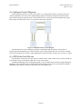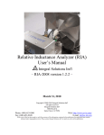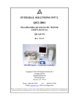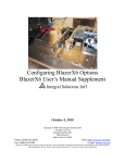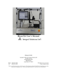
1
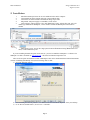
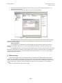
ESD Hardware Option Manual Integral Solutions Int'l – EPS-100 – August 22, 2013 Copyright 2003-2013 Integral Solutions Int'l All rights reserved Integral Solutions Int'l 3000 Olcott St Santa Clara, CA 95054 Phone: (408) 653-0300 Web: http://www.us-isi.com/ Fax: (408) 653-0309 E-mail: [email protected] While every effort has been made to verify the accuracy of the information contained in this publication, this publication may contain technical and/or typographical errors. Please contact Integral Solutions Int’l to report any errors in this publication. Contents 1. HARDWARE DESCRIPTION 3 2. INSTALLATION 4 3. MAINTENANCE 5 4. CHARGE DEVICE MODEL (CDM) 6 4.1 4.2 4.3 4.4 4.5 MECHANICAL ALIGNMENT MONITORING WAVEFORM ESD STANDARD CALIBRATION CDM OPERATION 6 7 8 10 12 5. MACHINE MODEL (MM) 13 5.1 5.2 5.3 5.4 5.5 MECHANICAL ALIGNMENT MONITORING WAVEFORM ESD STANDARD CALIBRATION MM OPERATION 13 14 15 16 17 6. 6.1 6.2 6.3 6.4 HUMAN BODY MODEL (HBM) MONITORING WAVEFORM ESD STANDARD CALIBRATION HBM OPERATION 18 18 19 20 21 7. ESD SWEEP TEST 22 8. BAR ESD STRESS OPTION 23 8.1 8.2 8.3 8.4 8.5 9. BAR ESD OPTION INSTALLATION MONITORING THE WAVEFORM ON BAR HBM/MM CHANGING THE WAVEFORM MODULE SOFTWARE CONTROL DIAGRAM ESD PROBE CARD PIN-OUT HIGH FIELD ESD STRESS OPTION 23 25 27 28 28 29 10. CONTACT INFORMATION 29 11. TABLE OF FIGURES 30 EPS-100 Manual Integral Solutions Int’l August 22, 2013 1. Hardware Description ESD Hardware Option is designed as an add-on to ISI QST-200x testers to study sensitivity of magnetoresistive heads to electro static discharge. ESD stress can only be done at HGA level and can be run in either standalone mode or as part of QST test. ESD option consists of EPS-100 and waveform module. EPS-100 is a power supply, capable of producing +/100V with 0.003V resolution. It is universal for all waveform modules. Due to calibration for more precise HBM and MM amplitude, the waveform module may require voltages slightly higher than 100, which is not supported by EPS-100. Therefore the maximum HBM and MM firing voltage is +/-90V. Waveform module is responsible for producing a pulse of a known shape (using one of the standard ESD models) and switching the head from stressing to testing. There are three standard types of waveform modules: Charge Device Model (CDM), Human Body Model (HBM), and Machine Model (MM). Newer waveform modules are located directly on the 2xHGA cartridge in close proximity to the head, and are called cartridge-style. Such modules can be run standalone or mounted on 2x tooling directly for testing. Older type module is an add-on to QST that has two 6-pin cables running to standard QST 2xHGA cartridge, and is called a box-style module. HBM and MM box-style waveform modules do not support any AC measurements. These modules are no longer manufactured, however EPS-100 supports them as well. A special adapter board for EPS-100 is required to run the box-style waveform modules. HBM and MM modules are universal for any flex design; custom mechanics that are required for different heads are located on the cartridge. So HBM and MM waveform modules can be freely interchanged on one cartridge. CDM waveform module on the other hand requires unique mechanical configuration for each flex design, and cannot be mounted on HBM/MM cartridge. EPS option was designed to work with the automated ESD Sweep test. The test uses EPS to generate controlled ESD transients and measures head parameters between the pulses to find ESD failure threshold (voltage). Any QST200x test, including AC measurements, can be used to characterize the head and find the ESD failure threshold. QST test requires a QST-200x and either 2xHGA tooling (for cartridge style waveform modules) or 8xHGA tooling for box-style. To enable this test, add ESDApp.Application to Quasi97 Selected Modules and enable it. !Important! It is not recommended to expose any waveform module to magnetic fields higher than 250Oe. When running QST tests with waveform module close to the magnet, make sure that magnetic field from the QST magnet does not cause field near waveform modules to exceed 200Oe. On standard 2-pole HSA/HGA magnet the module is physically inside the magnet so 250Oe limit applies. However, other magnet design (for example 4-pole or 15K high field) can go to higher fields without affecting the waveform module due to smaller field leakage in the perimeter. For example QST-2002HF Tester and QST-2002 with Quad-Pole HGA Magnet can go to higher fields. !Important! The diodes on Gen2 2xHGA cartridges must be removed in order to work properly with Machine Model (MM) and Human Body Model (HBM) ESD modules. So the “MR Clamping During Write” feature is not supported by the HBM/MM Gen2 type cartridges. User must remember the fact that the QST-2002 tester cannot recognize if the diodes are present or not, so “MR Clamping During Write” even though available in software, will not work. The diode protection still exists on the 2xHGA GEN2 interface board, using programmable clamping voltage, but it is enabled in both write and read modes. !Important! On Gen2 2xHGA type cartridges, for HBM and MM, the DC cable makes a slight impact on the waveform with higher resistance read heads. While it is recommended to have it for higher accuracy measurement, it has negative impact on the amplitude of the HBM waveform (HBM peak on 500ohm reader is ~5% higher with the DC ribbon cable because of additional capacitance). In order to avoid this phenomena, the DC ribbon cable between the cartridge and HGA connector board can be removed. In this case the cartridge needs to be reworked as follows: 1) On HGA connector board - remove the R5 and R7. 2) On the G2 2x Universal Cartridge board, install 0ohm resistors on R5-R10. Page 3 EPS-100 Manual Integral Solutions Int’l August 22, 2013 2. Installation 1. 2. 3. 4. 5. 6. 7. Install the NI-DAQ PCI-6503 in one of available PCI slots in the computer. Connect EPS-100 to the NI-Daq card using a 50-pin ribbon cable. Connect the waveform module to the EPS-100 using 26-pin cable. Plug in EPS-100 power supply to a standard 115VAC outlet. Turn on the PC, and run Quasi97. Go to File Hardware Config. Add one line item, select for module type EPS100Lib.clsHOption, * in the instance column and ESD Option in the function column. Select a setup file. In the Add-Ins Selected modules, enable ESDApp.application. ESD option is ready. You can fire single pulses from File menu, or run an ESD Sweep test. HardwareConfig EPS100Lib User If you are installing the EPS-100 option on the new PC, you need to install the NIDAQmx 9.7 software. The NIDaqmx Core link is available on www.us-isi.com – this is the bar minimum required to run. There is also an option to install full version of NIDAQmx. This can be downloaded from National Instruments website. If installing full NIDAQ version, then following must be done: 1) Select the following options. 2) After Installing the NI-DAQ software, run “Measurement and Automation Explorer” from your Desktop. 3) Go to "Devices and Interfaces", click "View"-->"Refresh". Page 4 EPS-100 Manual Integral Solutions Int’l August 22, 2013 4) The new PCI-6503 card should appear on the list. Click on the PCI-6503 card, then "Properties" - the software will verify the card. 5) After than close Measurement and Automation Explorer and Start Quasi97. Figure 2-1 – Measurement and Automation Explorer The 50pin ribbon cable with the choke between QST Universal Interface and 2xHGA tooling is to reduce AC noise on 2xHGA ESD option. It should be used if ESD Option is installed, and does not have any effect on standard non-ESD cartridgees. 2xHGA Gen2 Users: For CDM ESD test, you should have a special cartridge that does not have DC cables and connectors installed. The CDM cable splits into 2 AC cables (write and read) that should be connected to the back of the cartridge. For MM/HBM ESD test, you should reuse the non-ESD cartridge. You have to disconnect the 4 AC cables, then install a shim and put on the ESD waveform module. Then connect the waveform module to the cartridge via Y-type AC cable. Then connect the waveform module to the Connector board via 1" Y-Type AC cable. The DC cables should remain connected. 3. Maintenance Approximated lifetime of the relay on DCDM modules is 100,000 cycles. HBM and MM modules are less sensitive to a small change of capacitance in the relay, and will work longer without changing it. Performance of your waveform module should be monitored periodically, and, if necessary, the module should be sent back to ISI for relay replacement or calibration. Follow calibration procedures to ensure performance of your ESD Stress system. There is a 100mA SLO-BLO fuse on the AC input. Page 5 EPS-100 Manual Integral Solutions Int’l August 22, 2013 4. Charge Device Model (CDM) 4.1 Mechanical Alignment According to CDM standard, the head’s suspension must be grounded. In most cases suspension holder serves that purpose, while in other, the suspension is pressed against CDM chassis by flex clamp. Unlike HBM or MM modules, CDM cartridge requires the flex to be directly connected to the board. That is why mechanical alignment of CDM cartridge may be counterintuitive. The pads on the flex must be facing the board, so for some cases, the head will be mounted ABS side up. The head will still be kept horizontal (90° to the transverse field). Suspension Holder Flex Guide Flex Clamp Figure 4-1 CDM Mechanical Alignment Up/Down head reconfiguration involves changing the flex guide and realigning the suspension holder. Align the suspension holder so that the head’s flex is on the centerline of the CDM tooling and the lies on the 2(4) pogo pins. Usually ISI ships two flex guides for Up/Down heads: user needs to remove the two screws holding the flex guide and change it. Head’s flex should always lie on the 2(4) pogo pins, on the centerline of CDM tooling. If screws from the flex guide are missing the user should remove the pins and put them into different pinholes to match head type. CDM cartridge can support heater, but a special cable should be used (that connects to pins 3 and 4 of the Write port on the 2xCartridge). Use "Static Test"."Aux Point Test" to measure resistance of the heater in ESD and nonESD configuration. Note for 4-Pole magnet applications On DCDM the flex is centered, but the suspension (and therefore HGA) is pivoted. This means there may be an offset (top view) of both the UP and DN sliders, and each may be at an angle (mirror image top view). The offset user can manually compensate by moving the magnet left or right. However, the angle will be an issue. For Transverse testing this is no problem, assuming the MR itself is centered in the gap. But for rotating fields the head will see different result than if the head was placed perpendicular into the gap. So for Quad-Pole and HGA-only magnets user must ensure that the MR-element is within the uniform zone of the magnet gap. Secondly, Transverse-only field is recommended if the suspension is at any angle to the magnet other than 90degrees. Page 6 EPS-100 Manual Integral Solutions Int’l August 22, 2013 4.2 Monitoring Waveform CDM waveform module charges the head to desired voltage and then grounds it, which creates a very fast current transient from the charge accumulated on the head. The pulse is very fast with the rise time up to 500pS and pulse width up to 1nS. The screenshot below is 5V CDM pulse, fired into a real head. Figure 4-2 Monitoring CDM Pulse (fired into real head) The shape and amplitude of the pulse you see on the screenshot is going to depend on the electrical properties (capacitance) of the head. The CT-6 probe comes standard with CDM cartridge and should be ready for monitoring the waveform. Simply connect the CT-6 current probe from CDM waveform module to the oscilloscope. If CT-6 is not installed, we recommend sending it to ISI. If that is not possible, here is the procedure on how to do it: Separate the waveform module from the 2x cartridge, by removing 4 screws that are not covered in black. Fix the waveform module as shown on the picture (right). Push the CT-6 probe through the opening on the bottom, up towards the copper wire. Unsolder the copper wire on the right end. Insert wire through the CT-6 probe and re-solder. Mount DCDM waveform module back on the cartridge. Figure 4-3 CDM CT-6 Page 7 EPS-100 Manual Integral Solutions Int’l August 22, 2013 4.3 ESD Standard The standard shown here applies to pulses produced by ISI DCDM waveform modules and should treated as such. The values should be used for verification of the CDM waveform module device with 5pF and 12pF calibration capacitors. 300 200 IP1 Current (mA) 100 td Ip3 Ip2 0 -2 -1 0 -100 1 2 3 4 5 6 tr -200 Time (ns) Figure 4-4 CDM Standard 1 Ip1 can be estimated as 11mA/V CDM for 5pF capacitor and 13mA/V CDM for 12pF at 10V CDM or higher. The real peak current at lower voltages (such as 1V CDM) is around 8mA/V and 12mA/V for 5pF and 12pF capacitors. Use the following table to verify performance of your CDM module. Ip1 / CDM Voltage Nominal 1 10 20 8.2 104.5 215.6 10.4 1 130.9 10 268.2 20 Other parameters can be checked at 10V CDM: Minimum Maximum 5 pF Ca l ib ra t io n Ca pa c it o r 6.6 9.8 83.6 125.4 172.5 258.7 1 2 pF Ca l ib ra t io n Ca pa cit o r 8.3 12.5 104.7 157.0 214.6 321.8 Symbol 5pF 12pF Rise Time (10% – 90% of Ip1) tr <0.5 ns <0.6 ns Width at 50% of Ip1 td 700 ps 1000 ps2 Max 2nd peak Ip2 <50% Ip1 <50% Ip1 Ip3 <25% Ip1 <25% Ip1 rd Max 3 peak The values above were measured using LeCroy LC574A 1Ghz oscilloscope. We expect that faster oscilloscope would show slightly higher amplitude and smaller pulse width. 1 Figure taken from Standardized Direct Charge Device ESD Test For Magneto resistive Recording Heads II. Lydia Baril, Tim Cheung, Albert Wallash. 2 The waveform rise time and width is overall 5% higher at bar CDM then on 2xHGA, because calibration capacitor is mounted in different location. Page 8 EPS-100 Manual Integral Solutions Int’l August 22, 2013 The following plot shows real 20V CDM discharge on 5pF calibration capacitor. Figure 4-5 CDM Waveform (5pF Capacitor) Page 9 EPS-100 Manual Integral Solutions Int’l August 22, 2013 4.4 Calibration Use one of the calibration capacitors to verify the CDM waveform. Turn on the EPS-100. If running Quasi97 software then exit from it and run EPS-100 application. Also remove the CDM cartridge from the 2xHGA tooling. To install a calibration board, remove the HGA flex clamp and flex guide for Up/Down Heads from the cartridge. Pull out a pin from plastic base (where you put in the flex of HGA); the HGA clamp along with the spring should come out. If flex guide is held by two screws then remove them and pull out the flex guide. If flex guide is glued then remove the locating pins from it. You should have a cartridge with 2 or more uncovered pogo pins. Figure 4-6 CDM Cartridge Calibration Put the calibration board on top of the pogo pins. The calibration capacitor board should reside on two reader pogo pins and contact the CDM chassis on the sides. So when installing it make sure that the two MR pogo pins do contact the metal portion of the disk capacitor and writer pins do not. There are two methods of locating the calibration capacitor: If there is a pinhole before pogo pin 1, insert the pin that you removed earlier in that hole through the calibration board (use the pin to guide the calibration board to the proper location). If a guide hole (or a pin) is not available then use an ohmmeter to locate the calibration board. To do that, restart EPS-100 software; connect the ohmmeter to pins 1 and 2 of J2 connector, and continuously measure resistance while moving the calibration capacitor until you get less than 1 Ohm. After that, check resistance between pins 2 and 3 to make sure that R+ and W- are not connected. Put 2 screws with washers on two sides of the calibration board to hold it in place and to connect the topside of the board with the CDM chassis. Fire a 1, 10 and 20V pulses and verify the amplitude, pulse width and rise time against CDM standard. Page 10 EPS-100 Manual Integral Solutions Int’l August 22, 2013 BlazerX5 version of the CDM waveform module has pogopins on the other side of the board. For verification of the waveform, the module has to be mounted on the support plate and the calibration disk should be mounted on a shim, as shown on the picture below. Figure 4-7 BlazerX5 CDM Calibration 1 CDM Waveform Module 2 Support Plate 9 Calibration Disk 10 Special Shim 12 Screw 13 Flat washer Page 11 EPS-100 Manual Integral Solutions Int’l August 22, 2013 4.5 CDM Operation The following block diagram is provided for better understanding of the operation of the waveform module. It is created to show the charge device model ESD standard. The actual waveform module circuit may be slightly different. Figure 4-8 CDM Block Diagram To fire pulse: 1) S1-UP, S2-DN, S3-UP 2) wait 100mS 3) S1-DN To test: 1) S1-DN, S2-UP, S3-DN Page 12 EPS-100 Manual Integral Solutions Int’l August 22, 2013 5. Machine Model (MM) 5.1 Mechanical Alignment MM cartridge does not require a special mechanical alignment. It connects to the board with pogo pins on the cartridge through a short cable. The waveform module can be connected to only one head at a time. In the case where cartridge has two pogo-pin boards for up and down heads, connect the cable from one or the other board to the waveform module. Figure 5-1 MM / HBM Mechanical Alignment To switch from MM to HBM, simply remove the two screws on the topside of the waveform module and disconnect three cables from it (EPS-100 cable, QST and pogo-pin board connection). The waveform module should come off and you can install another one (HBM or MM) in its place. On 2xHGA Gen2 HBM/MM ESD cartridges do support heater testing (the aux bias current goes though the DC cables). Use "Static Test"."Aux Point Test" to measure resistance of the heater in ESD and non-ESD configuration. Page 13 EPS-100 Manual Integral Solutions Int’l August 22, 2013 5.2 Monitoring Waveform To monitor current going through the head install a CT-1 probe on the wire going from J4 Pin2 on the cartridgestyle waveform module to the FIC board. For the box-style modules mount CT-1 on the wire going from pin2 of “HEAD” connector on waveform module. Figure 5-2 Monitoring MM Pulse The following screenshot shows a 10V discharge into 500Ohm resistor. Figure 5-3 MM 500Ω Discharge Page 14 EPS-100 Manual Integral Solutions Int’l August 22, 2013 5.3 ESD Standard Machine Model charges a 200pF capacitor and fires the accumulated charge into the head. The standard shown here applies to pulses produced by ISI MM waveform modules and should treated as such. Voltage Level (V) 10 Positive IPEAK for Short, IPS1 (mA) 150 – 200 Current at 100ns for 500Ω I100 (mA) 7.25 +/- 20% Maximum Positive IPEAK for 500Ω IPR (mA) I100 * 4.5 Maximum Ringing Current, IR (mA) IPS1 * 30% Resonance Frequency for Short, FR (1/tfr) (MHz) 11–15 Figure 5-4 Short and 500Ω MM Standard 3 3 Figure Taken from EIA/JEDEC Standard. Test Method A115-A. Electrostatic Discharge Sensitivity Testing Machine Model (HBM). Revision EIA/JESD22-A115. Page 15 EPS-100 Manual Integral Solutions Int’l August 22, 2013 5.4 Calibration To verify calibration of the machine module, mount a CT-1 probe to monitor the ESD pulse. Connect a 0Ω resistor instead of the head and fire a 10V pulse. Verify the peak amplitude and ringing frequency against that in the MM spec. Connect a 500Ω resistor and fire a 10V pulse. Check that amplitude and current at 100nS conforms to Machine Module specification. Figure 5-5 New-Style MM-HBM Calibration The picture above shows the cartridge-style machine module prepared for calibration. See HBM calibration for a picture of box-style waveform module calibration. Note that the same ESD waveform specification applies to both cartridge and box – style MM. Figure 5-6 MM 10V Discharge into a 0Ohm Resistor Page 16 EPS-100 Manual Integral Solutions Int’l August 22, 2013 5.5 MM Operation The following block diagram is provided for better understanding of the operation of the waveform module. It is created to show the machine model ESD standard. The actual waveform module circuit may be slightly different. Figure 5-7 MM Block Diagram To fire pulse: 1) S2-Right, S1-Right, S3-Up 2) wait 100mS 3) S2-Left To test device: 1) S3-DN Page 17 EPS-100 Manual Integral Solutions Int’l August 22, 2013 6. Human Body Model (HBM) 6.1 Monitoring Waveform Capturing the waveform of HBM pulse requires the same setup as on Machine Model. To monitor current going through the head install a CT-1 probe on the wire going from J4 Pin2 on the cartridge-style waveform module to the FIC board. For the box-style modules mount CT-1 on the wire going from pin2 of “HEAD” connector on waveform module. Figure 6-1 Monitoring HBM Pulse HBM/MM ESD catridge do support heater testing (the aux bias current goes though the DC cables). Use "Static Test"."Aux Point Test" to measure resistance of the heater in ESD and non-ESD configuration Figure 6-2 HBM 50V with 500Ohm Resistor Page 18 EPS-100 Manual Integral Solutions Int’l August 22, 2013 6.2 ESD Standard Human Body Model charges 100pF capacitor and fires accumulated charge through the 1500Ω resistor into the head. The standard shown here applies to pulses produced by ISI HBM waveform modules and should treated as such. Voltage Level (V) 7 50 IP0Ω (MR) for Short (mA) 4.2 – 5.15 30 – 36.7 IP500Ω (MR) for 500Ω (mA) 2.63 – 4.2 18.75 – 30 (V) 6.3 – 7.7 45 – 55 (V) 5.25 – 8.4 37.5 – 60 (nS) 2 – 10 Rise Time for 500Ω (nS) 5 – 25 Decay Time for Short (td) (nS) 130 – 170 Decay Time for 500Ω (nS) 160 – 240 Ringing Current (IR) (mA) 15% of IPS 4 VPEAK (on R1) for Short (IPEAK *1500/1000) VPEAK (on R1) for 500Ω (IPEAK *(1500+500)/1000) Rise Time for Short (tr) Figure 6-3 Short and 500Ohm HBM Standard 5 4 R1 is 1500Ω Resistor in series with the MR head inside the HBM waveform Module. Vpeak is directly proportional to Ipeak, and the formula can be used to calculate real HBM voltage applied. 5 Figure Taken from EIA/JEDEC Standard. Test Method A114-A. Electrostatic Discharge Sensitivity Testing Human Body Model (HBM). Revision EIA/JESD22-A114. Page 19 EPS-100 Manual Integral Solutions Int’l August 22, 2013 6.3 Calibration To verify calibration of the human body module, mount a CT-1 probe to monitor the ESD pulse. Connect a 0Ω resistor instead of the head and fire a 7V and 50V pulse. Verify the peak amplitude, rise and decay times against the HBM spec. Connect a 500Ω resistor and fire a 7 and 50V pulses. Verify the waveform characteristics with the spec. Figure 6-4 Old-Style MM-HBM Calibration The screenshot above shows the box-style HBM prepared for calibration. See MM calibration for screenshot of cartridge-style waveform module calibration. Note that the same ESD waveform specification applies to both box and cartridge – style HBM. Figure 6-5 Real HBM Discharge on 0Ohm resistor Page 20 EPS-100 Manual Integral Solutions Int’l August 22, 2013 6.4 HBM Operation The following block diagram is provided for better understanding of the operation of the waveform module. It is created to show the human body model ESD standard. The actual waveform module circuit may be slightly different. Figure 6-6 HBM Block Diagram To fire pulse: 1) S2-Right, S1-Right, S3-Up 2) wait 100mS 3) S2-Left To test device: 1) S3-DN Page 21 EPS-100 Manual Integral Solutions Int’l August 22, 2013 7. ESD Sweep Test ESD option allows you to fire a sequence of pulses and monitor head performance during the sweep. To enable it run Quasi97, go to Add-Ins Modules and enable ESDApp.application. ESDApp is a test that will use your ESD option to fire pulses into the head and will run transfer curve (or any other test) to see how the head had degraded. It is not recommended to expose any waveform module to magnetic fields higher than 250Oe. When running QST tests with waveform module close to the magnet, make sure that magnetic field from the QST magnet does not cause field near CDM waveform module to exceed 200Oe. Figure 7-1 ESD Sweep Figure 7-2 ESD Sweep Transfer Curve Plot See Quasi97 External Tests manual for more information how to ESD Sweep test. Page 22 EPS-100 Manual Integral Solutions Int’l August 22, 2013 8. Bar ESD Stress Option The ESD Stress option can also be mounted on the BlazerX5 bar tester, for testing heads while they are still on the row bar. This arrangement requires standard PCI-6503 card and EPS-100 modules. It also required modified waveform module, stress probe card base and stress probe card. Figure 8-1 Bar ESD Stress Option This manual will describe the installation of the ESD stress option onto the BlazerX5 bar tester, instructions on changing the waveform module and monitoring the ESD waveform. For ESD Stress probe card alignment and setting up stress positions, please refer to BlazerX5 Users Manual. 8.1 Bar ESD Option Installation For installation turn off the BlazerX5. 1. Install PCI-6503 card in one of the available PCI slots in the comuter 2. Install the shelf for EPS-100 on the right side of the tester (leaving the 50pin ribbon cable between the shelf then the right panel of the Blazer). Figure 8-2 EPS-100 BlazerX5 Installation 3. Route the ribbon cable into the lower frame and connect to the PCI-6503 card inside the computer. Connect the AC power to the EPS-100. Page 23 EPS-100 Manual Integral Solutions Int’l August 22, 2013 Figure 8-3 EPS-100 BlazerX5 Installation (2) 4. Mount the EPS-100 on the shelf and connect all cables to it. Figure 8-4 EPS-100 BlazerX5 Installation (3) 5. Remove one from bar magnet assembly and install the waveform module holder. Page 24 EPS-100 Manual Integral Solutions Int’l August 22, 2013 8.2 Monitoring the waveform on Bar HBM/MM Unlike the standard HBM/MM cartridges, the BlazerX5 HBM/MM don’t have connectors for the flex guide cables. Instead the have pogo-pins which connect to the probe card PCB. BlazerX5 HBM/MM waveform modules have a special slot in the enclosure specifically for the CT-6 installation. Figure 8-5 BlazerX5 HBM/MM – Connecting CT-6 1. 2. To install the CT-6, you have to remove the BlazerX5 waveform module assembly from the base, just as you would when changing the stress probe card (see BlazerX5 User Manual). This is done by removing two screws from the top plate of the assembly. Remove the waveform module from the assembly. Figure 8-6 BlazerX5 HBM/MM – Connecting CT-6 (2) 3. Remove 4 on the bottom of the pomalux enclosure to take it apart. Figure 8-7 BlazerX5 HBM/MM – Connecting CT-6 (3) Page 25 EPS-100 Manual 4. Integral Solutions Int’l August 22, 2013 Install the CT-6 onto the outside pogo pin, such that the green dot on the CT-6 is facing the PCB. Figure 8-8 BlazerX5 HBM/MM – Connecting CT-6 (4) 5. 6. Put the assembly back together. To avoid damage to the vacuum gripper or to the pogo pin, secure the CT-6 with the tie wrap after the waveform module is installed on the tester. To monitor the waveform on a real head, you need to load a bar in Barcont, then select “Stress” location, move to a slider on the bar and click “Probe”. You can open the EPS-100 main menu from the ESD Sweep Test option, and then fire single pulses using EPS-100. To monitor the waveform on a resistor probe card, you need to install the dummy (resistor) probe card first and then mount the waveform assembly onto the Blazer. After that you can fire pulses using EPS-100 application. The waveform should comply with HBM/MM standards specified in this manual. Page 26 EPS-100 Manual Integral Solutions Int’l August 22, 2013 8.3 Changing the Waveform Module To change the waveform module, first remove the waveform module assembly from stress probe card base and then unscrew the two screws holding the waveform module to the assembly (as shown on the picture below). Figure 8-9 Changing the Waveform Module (BlazerX5) Loosen all 4 screws holding the base with the probe card, as you would when realigning the probe card. You need to do that because different modules will allow access to different probe card alignment screws. For example HBM/MM allows access to left-back, right-back and right-front screw; whereas CDM allows access to righ-back, left-front and right-front screw. You will need to tighten any two screws to hold the probe card base firmly in place. Figure 8-10 CDM Waveform Module (BlazerX5) Install the waveform module in the opposite order (first install the module onto the assembly, and then install assembly onto the stress probe card base). Note that when changing the module from HBM/MM to CDM or vice versa, you will have to change the screws in Step1 and Step2 with the ones supplied with the module you are attempting to install. Page 27 EPS-100 Manual Integral Solutions Int’l August 22, 2013 8.4 Software Control Diagram For Bar ESD Stress option, you need to select “Bar Level” configuration in Quasi97 setup selection screen (instead of QST2002). You also need to enable ESDApp.Application module in the Quasi97 selected modules menu. When running, the ESD Sweep test will tell barcont to move to stress location, then tell EPS-100 to apply ESD voltage, then tell barcont to move to test location and run tests in Quasi97. Figure 8-11 Bar ESD Software Control Diagram The ESD Sweep Test can be enabled in production. For BlazerX5 ESD, this allows to run a full bar in engineering mode and multiple trays of bars in operator mode, without operator input. Be careful not to run ESD sweep test in production if you want to enable logging plots, because Excel file is going to get very big very quickly. 8.5 ESD Probe Card Pin-out The ESD probe card has only two pins, which are connected to R+ and R- outputs of the waveform module. R+ is the pin that is closer to the magnet, and R- pin is closer to the operator. For HBM and MM the pulse is discharged through R+ side. For CDM module, the head is charged through Rand then R- side is grounded, and R+ remains floating during discharge. So the active pin is different on CDM vs HBM/MM, but the polarity of the pulse remains the same on all module types. Page 28 EPS-100 Manual Integral Solutions Int’l August 22, 2013 9. High Field ESD Stress Option HBM and MM ESD modules are fully compatible with High Field tester, CDM module requires a rework. For more information and operation specifications please refer to QST-2002-HF User’s Manual. 10. Contact Information Integral Solutions Int'l 3000 Olcott St Santa Clara, CA 95054 Phone: Fax: E-mail: Web: (408) 653-0300 (408) 653-0309 [email protected] http://www.us-isi.com/ Page 29 EPS-100 Manual Integral Solutions Int’l August 22, 2013 11. Table of Figures Figure 1 CDM Mechanical Alignment Figure 2 Monitoring CDM Pulse (fired into real head) Figure 3 CDM CT-6 Figure 4 CDM Standard Figure 5 CDM Waveform (5pF Capacitor) Figure 6 CDM Cartridge Calibration Figure 7 BlazerX5 CDM Calibration Figure 8 CDM Block Diagram Figure 9 MM / HBM Mechanical Alignment Figure 10 Monitoring MM Pulse Figure 11 MM 500Ω Discharge Figure 12 Short and 500Ω MM Standard Figure 13 New-Style MM-HBM Calibration Figure 14 MM 10V Discharge into a 0Ohm Resistor Figure 15 MM Block Diagram Figure 16 Monitoring HBM Pulse Figure 17 HBM 50V with 500Ohm Resistor Figure 18 Short and 500Ohm HBM Standard Figure 19 Old-Style MM-HBM Calibration Figure 20 Real HBM Discharge on 0Ohm resistor Figure 21 HBM Block Diagram Figure 22 ESD Sweep Figure 23 ESD Sweep Transfer Curve Plot Figure 24 Bar ESD Stress Option Figure 25 EPS-100 BlazerX5 Installation Figure 26 EPS-100 BlazerX5 Installation (2) Figure 27 EPS-100 BlazerX5 Installation (3) Figure 28 BlazerX5 HBM/MM – Connecting CT-6 Figure 29 BlazerX5 HBM/MM – Connecting CT-6 (2) Figure 30 BlazerX5 HBM/MM – Connecting CT-6 (3) Figure 31 BlazerX5 HBM/MM – Connecting CT-6 (4) Figure 32 Changing the Waveform Module (BlazerX5) Figure 33 CDM Waveform Module (BlazerX5) Figure 34 Bar ESD Software Control Diagram Page 30 6 7 7 8 9 10 11 12 13 14 14 15 16 16 17 18 18 19 20 20 21 22 22 23 23 24 24 25 25 25 26 27 27 28