1
2
CONTENTS
PRECAUTIONS .................................................. 4
COMPONENTS AND THEIR NAMES ..... 6
INSTALLATION .................................................. 8
WARM-UP ............................................................ 10
MESURING PROCEDURE ...........................11
MENU SELECTION ........................................ 12
1. Menu selection when “
” is selected 14
2. Menu selection when “
” is selected ..... 16
SENSITIVITY CALIBRATION ................... 17
1. Setting the value of sensitivity calibration weight......... 17
2. Sensitivity Calibration.............................................. 19
REGISTRATION, CANCEL,AND CHANGE OFUNIT 20
% SETTING ......................................................... 21
PCS (No. of pieces) SETTING........................ 22
PERFORMANCE CHECKS ........................ 23
MAINTENANCE ............................................... 24
TROUBLESHOOTING .................................. 25
SPECIFICATIONS ............................................ 26
PARTS LIST ......................................................... 27
PERIPHERAL DEVICES .............................. 28
1. The EP-60A Electronic Printer.................................. 28
2. The IFB-102A RS-232C Interface............................. 29
3. Input/output Format................................................. 31
4. Command Code ..................................................... 32
3
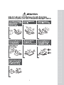
PRECAUTIONS
4
5
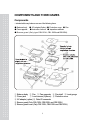
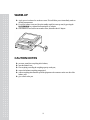
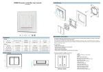
COMPONENTS AND THEIR NAMES
Components
- Included with every balance are one of the following items.
● Balance body ● AC adapter(Option) ● Protection cover ● Pan
● Pan supporter ● Instruction manual ● Inspection certificate
● Breeze guard (Only type CBL120H, CBL 220H and CBL320H).
① Balance body ② Pan ③ Pan supporter ④ Pan shaft ⑤ Level gauge
⑥ Power jack
⑦ Level screws (3 places) ⑧ Protection cover
⑨ AC adapter (option) ⑩ Data I/O connector
⑪ Breeze guard (Only CBL120H, CBL220H and CBL320H)
⑫ Breeze guard cover (Only CBL120H, CBL220H and CBL320H)
6
Display and keypad
Display
Sensitivity calibration mark
Stability mark
Analog indicator
Communication mark
Auto print mark
Standby mark
Unit mark
Keypad
KEY
POWER/BAK
CAL/MENU
FUNCTION
Selects Operation / Warm-up.
Cancels calibration or menu.
Performs calibration.
Selects a menu.
TARE
Clears the display to zero.
Sets a menu.
UNIT
Selects a unit.
Sets % or No. of pieces.
Sets a value of sensitivity calibration weight.
PRINT
Outputs the displayed value to a printer or orther extemal equipment.
Sets a value of sensitivity calibration weight.
]
7
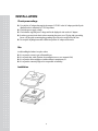
INSTALLATION
Check power voltage
▶ Use only the AC adapter that supplys the output of 12VDC or the AC adapter provided by the
distributor who is authorized by CAS Corporation.
▶ Check the power supply voltage.
▶ Check that the supplied power voltage satisfies the displayed value on the AC adaptor.
▶ In order to prevent electric shock when connecting the power, use a 3P plug with a grounding
line or a 2P plug after connecting the grounding wire to the screw at the back of the case.
▶ Do not place anything that makes it difficult to pull the AC adapter off the outlet.
Site
Avoid installing the balance in a place where:
▶ It is exposed to corrosive gas or flammable gas;
▶ It is exposed dust, wind, vibration, electromagnetic waves, or a magnetic field;
▶ It is exposed to direct sunlight or a sudden change in temperature; or
▶ It is exposed to extremely high or low temperature or humidity.
Installation
8
(1) Remove the protection seals (4 places) from the protection
cover and then put it on the balance body.
(2) Turn the level screw so that the air bubble on the level gauge is
positioned at the center of the red circle. Make sure that the
balance never jolt.
For easy adjustment, insert the level screw on the right back
forcibly to the balance body. Then while lightly pressing the
balance top with your hand, adjust the horizontal level with the
level screws on the right front and left front.
Finally, in order to make the balance stable, adjust the right back
screw to touch the floor.
This procedure allows you to level the balance quickly.
(3) Place the pan supporter on the pan shaft and then the pan on the
pan supporter.
(4) Plug the AC adapter into the outlet. The balance shows
“
” after self-checking.
(5) Press the POWER/BRK key. All displays light for one
minute. Then the display automatically shows "zero" and the
balance enters measurement ready state.
(6) Press the POWER/BRK key again. The standby mark lights
up and the balance enters standby state.
(7) Warm up the balance.
(8) Calibrate the sensitivity.
Refer to “7. SENSITIVITY CALIBRATION”.
(9) Check the performance.
Refer to “11. PERFORMANCE CHECKS”
9
WARM-UP
▶ Apply power in advance for one hour or more. This will allow you to immediately make an
accurate measurement.
▶ Even if the balance is not used, keep the standby mark lit (warm-up state) by pressing the
POWER/BRK key without disconnecting the AC adapter.
▶ If the balance is not used for one month or more, disconnect the AC adapter.
CAUTION NOTES
put water, metal pin or any thing in the balance;
open the balance case;
leave anything exceeding the weighing capacity on the pan;
expose the balance to anything magnetized;
connect anything other than the specified equipment to the connector on the rear side of the
balance; and.
▶ give a shock to the pan.
▶
▶
▶
▶
▶
10
MEASUREMENT PROCEDURE
Warm up the balance.
Preparation for Weighing Making a measure-ment mode
(1) Press the POWER/BRK key. The standby mark goes off
and all displays light. Check that there is no segment which is
not lit.
(2) The balance shows zero and enters the measurement mode
Measurement
(1) When using a tare, load the tare on the pan and press the
TARE key after a stability mark is lit.
(2) Check that the display shows zero.
(3) Load a sample. When the stability mark is lit, read the display.
If the total mass of the sample and tare exceeds the weighing
” will be displayed.
capacity, “
※ Tare : A sample container or other.
) : Lights when the displayed value falls within the stability band. When the
Stability mark(
load change is slow, the displayed value will fluctuate with the stability mark
lit.
11
MENU SELECTION
This balance is designed to permit selection of the measuring conditions to compensate for vibration
and other conditions present at the installation site. This feather permits greater weighing efficiency
and accuracy, and is referred to as “Menu Selection”.
Also in CBL series, setting the balance to “
” (standard measurement mode) makes a
normal measurement and requires no other setting.
The menu in the CBL series consists of three classifications. Basically press the TARE
key to go to lower hierarchy, and press the POWER/BRK key to return to upper
hierarchy. Continuously pressing the POWER/BRK key returns the display to weight
display from each hierarchy with single operation.
Step
(1) Press the CAL/MENU key during the weight display.
(2) “
” will be displayed.
(3) Every time the CAL/MENU key is subsequently pressed, the display be changed in the order
shown below.
(4) Select the desired condition and press the TARE key. Then, it will be set or enter into the lower
hierarchy.
12
Weight display
Sensitivity calibration mode
Currently set condition
Standard mode
Sample pouring mode
High stability mode
Enters second hierarchy menu. Advanced measurement, unit
registration, and individual setting mode
☞ Refer to Section 6.1 “Menu selection when “
is selected”.
”
Enter second hierarchy menu. Setting the value of sensitivity calibration weight
☞ Refer to Section 7.2 “ Setting the value of sensitivity calibration weight”.
Enter second hierarchy menu. Input/output format setting mode
☞ Refer to Section 6.2 “ Menu selection when “
” is selected”.
Weight display
▶ If the measurement is done at severe measurement environment and the stability of the display is
” (high-stability mode).
not so good, set the balance to “
▶ When the high-speed sample pouring mode is executed, or the small mount of sample pouring is
” (sample mode).
done, set the balance to “
13
1. Menu selection when “
” is selected
Pressing the TARE key when the “
” is displayed at 1st hierarchy menu enters
2nd hierarchy menu.
In this menu, ON/OFF of zero tracking, setting the stability detection band, registration/cancel of unit,
ON/OFF of auto print, and ON/OFF of analog display are made.
Key operation and each setting are made as follows.
14
(→) : Press the TARE key.
(←) : Press the POWER/BRK key.
(↓) : Press the CAL/MENU key.
, satisfactory for most use, the stability mark lights when the display stays
◆ When set to
within +/-1 unit (the resolution value of the balance) for a fixed period time.
◆ When the display shows “
**,
*,
**,
**”, the
currently set conditions are displayed on **.
◆ Zero tracking eliminates zero drift, and should be on (
)for normal weighing.
When measuring weight changes over time, or when slowly adding a liquid or powder to the
balance, turn off (
) the zero tracking feature.
15
2. Menu display when
is selected
” is displayed at 1st hierarchy menu enters
Pressing the TARE key when the “
2nd hierarchy menu.
In this menu, the input/output format can be set.
Baud rate 300
Baud rate 600
Baud rate 1200
Baud rate 2400
Baud rate 4800
Baud rate 9600
Delimiter C/R
Delimiter L/F
Delimiter C/R+L/F
Delimiter Comma
Parity, even
Parity, odd
Parity, none
Stop bit 1
Stop bit 2
(→) : Press the TARE key.
(←) : Press the POWER/BRK key.
(↓) : Press the CAL/MENU key.
◆ When the display shows
**,
set conditions are displayed on **.
16
**,
**,
** , the currently
SENSITIVITY CALIBRATION
The electronic balance measures mass by electronicity compensating for terrestrial gravitation.
Since gravitation varies slightly in different regions, span calibration (sensitivity calibration) is required
when the balance is installed. Temperature also effects balance accuracy, and calibration must be
performed whenever a significant change occurs. It is good practice to calibrate the balance whenever
the balance is moved or unexpected shock is applied to the balance such that an article drops on the pan.
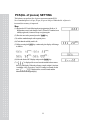
1. Setting the value of sensitivity calibration weight
In this balance, the value for sensitivity calibration weight can be set freely within the specified range.
Using the weight having known value, sensitivity calibration can be made.
Set the weight value using at sensitivity calibration as follows.
Step
(1) Following the menu selection, press the CAL/MENU key to
”.
make the display “
(2) Press the TARE key to set the balance to weight set mode.
(3) The weight value currently set is displayed and the digit to be set
blinks. When the weight value is not changed, press the TARE key.
(4) Pressing the PRINT key shifts the blinking digit.
(5) Pressing the UNIT key counts up the blinking displayed value.
(6) Repeats the steps (4) and (5) to set the weight value.
(7) When aborting the setting, press the POWER/BRK key. Then
” is displayed for several seconds, the balance stops
“
the setting of weight value and returns to weight display.
(8) After the setting of weight value is completed, press the TARE key.
(9) “
” is displayed for several seconds and the balance returns
to weight display.
(10) When setting the weight value exceeding the specified range,
” is displayed and then the balance returns to weight
“
display.
17
The settable weight value is follows.
CBL-220S
CBL-320S
CBL-620S
CBL-2200S
CBL-3200S
CBL-120H
More than 100g and less
than weighing capacity.
More than 150g and less
than weighing capacity.
More than 300g and less
than weighing capacity.
More than 1000g and less
than weighing capacity.
More than 1500g and less
than weighing capacity.
More than 50g and less
than weighing capacity.
18
CBL-220H
CBL-320H
CBL-1200H
CBL-2200H
CBL-3200H
CBL-3200HL
More than 100g and less than
weighing capacity.
More than 150g and less than
weighing capacity.
More than 500g and less than
weighing capacity.
More than 1000g and less
than weighing capacity.
More than 1500g and less
than weighing capacity.
2. Sensitivity Calibration
Perform the sensitivity calibration as follows.
Step
(1) Warm up the balance well. Refer to “3. WARM-UP”.
(2) Check leveling.
(3) Unload the sample on the pan and press the TARE key to zero the
display
(4) Following the menu selection, press the CAL/MENU key to
display “
”.
(5) Press the TARE key to start the sensitivity calibration.
(6) The set weight value appears and blinks
(7) Make sure that the stability mark is lit.
(8) Place the calibration weight on the pan. At this time, the stability
mark will once disappear.
(9) When the stability mark is lit again, press the TARE key.
(10) The display shows zero and blinks. Make sure that the stability
mark is lit.
(11) Unload the weight.
(12) When the stability mark is lit again, press the TARE key.
(13) “
” is displayed for several seconds and the
balance returns to weight display. This completes the sensitivity
calibration.
(14) If the different weight is used for this sensitivity calibration,
“
” is displayed for several seconds and the balance
returns to weight display. Check the weight and retry the
sensitivity calibration.
19
REGISTRATION, CANCEL, AND CHANGE OF UNIT
Step for registration
(1) Press the CAL/MENU key and select “
(Press the TARE key.)
” display.
(2) Press the CAL/MENU key and select “
” display.
(Press the TARE key.)
(3) The registrable unit is displayed by every pressing the CAL/MENU key. The registerable
units are three kinds which are selected from the following 14 kinds.
g, kg, ct. pcs, %, oz, ozt, dwt, GN, Hong-kong tail, Singapore tail, Taiwan tail, Maraysia tail, and
Japanese "monme"
However, % and pcs (No. of pieces) cannot be registered simultaneously.
The stability mark is lit on the unit display currently registered.
(4) Press the TARE key on the unit display to be registered. That unit is registered.
When three kinds of unit are already registered, a new registration deletes the oldest
registration among the three registered units. However, % and pcs (No. of pieces)
cannot be registered simultaneously. Then deletes unnecessary one.
(5) Continuously pressing the POWER/BRK key returns the display to weight display.
Step for cancel
(1) Carry out the same operation described (1) to (3) above to set unit display. Selecting the same
one of the unit display which is currently registered (stability mark is lit) cancels the registration.
Step for change
(1) Pressing the UNIT key changes the unit which is already registered.
However, even if the unit of % and pcs is already registered, the display does not change to this
unit unless making a setting of reference value.
20
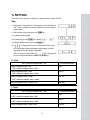
% SETTING
This balance serves percent (%) display by setting the reference sample to 100%.
Step
(1) Register the % unit. (Refer to “8. Registration, cancel, and change of
unit”. When % unit has been already registered, it is not necessary to
register again.
(2) Place the tare on the pan and press the TARE key.
(3) Load the reference sample.
(4) Continuously press the UNIT key to display “
”.
(5) After the stability mark is lit, press the TARE key.
” is displayed for several seconds and the balance enters
(6) “
the % unit display. Minimum displayed value changes as follows
depending on reference sample weight (REF.)
” is displayed for
If the % conversion is not possible, “
several seconds and the balance returns to weight display.
H Type
REF. < Minimum displayed value × 100
Minimum displayed value × 100
% conversion impossible
100%
< REF. < Minimum displayed value × 1000
Minimum displayed value × 1000
100.0%
< REF. < Minimum displayed value × 10000
Minimum displayed value × 10000
100.00%
< REF. < Minimum displayed value × 100000
100.000%
Minimum displayed value × 100000 < REF.
S Type
REF. < Minimum displayed value × 100
Minimum displayed value × 100
% conversion impossible
100%
< REF. < Minimum displayed value × 1000
Minimum displayed value × 1000
100.0%
< REF. < Minimum displayed value × 10000
100.00%
Minimum displayed value × 10000 < REF.
21
PCS(No. of pieces) SETTING
This balance can perform No. of pieces measurement(unit PCS.)
No. of standard pieces is 10 pcs, 20 pcs, 50 pcs or 100 pcs. When the No. of pieces is
increased, the accuracy is improved.
Step
(1) Register the PCS unit following the unit registration. (Refer to “8.
Registration, cancel, and change of unit”.) When PCS unit has been
already registered, it is not necessary to register again.
(2) Place the tare on the pan and press the TARE key.
(3) Load the standard sample with required pieces.
(4) Check that the stability mark is lit.
(5) When pressing the UNIT key continuously, the display will change
as follows:
“
”, “
”
“
”, “
”
(6) Select the desired PCS display and press the TARE key.
” is displayed for several seconds and the balance enters
(7) “
the PCS unit display. When the reference sample weight is less than
“readability x No. of set pieces”, the PCS setting is not made. In this
” is displayed for several seconds and the
case, “
balance returns to weight display.
22
PERFORMANCE CHECKS
Conduct performance checks in a room where the temperature does not change suddenly.
These checks are used to determine if the balance conforms to specifications, and should be
performed with the greatest care.
Preparation
※ Warm up the balance well.
※ Set the measurement condition as follows:
▶
▶
▶
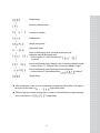
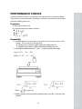
Repeatability
(1) Load and unload 10 successive times, an weight which is near the capacity of the
balance. Then record the following items:
Xi : Displayed value when the weight is loaded after stability mark is lit.
Yi : Displayed value when the weight is unloaded after stability mark is lit.
(2) Calculate the standard deviation of x and y using the formulas shown right.
Load : X1, X2, …, Xi, …, X10
↕
Unload : Y1, Y2, …, Yi, …, Y10
Where :
,
Average value
(3) Balance operation is normal when the standard deviation is less than 1.5 times the value
specified.
23
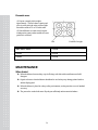
Eccentric error
(1) Prepare a sample which weights
approximately ¼of the balance capacity and
move it on the pan in the order as shown right.
Record the results of X1 to X5 in this order.
(2) If the difference (eccentric error) between
readings at the center position and the off center
positions is as follows:
Pan
320H, 3200H, 3200HL
7 Counts
H Series
4 Counts
S Series
2 Counts
Position of weight
MAINTENANCE
When fouled
▶ When the balance becomes dirty, wipe it off using a soft cloth with a small amount of mild
detergent.
▶ Organic solvents or chemical dusters should not be used as they may damage painted surfaces
and the display panel.
▶ When the balance is placed in a dusty or dirty environment, use the protection cover of standard
accessory.
▶ The pan can be washed with water. Dry the pan sufficiently and mount to the balance.
24
TROUBLESHOOTING
For countermeasures having an asterisk, contact the nearest CAS sales or service center.
When
Before
Weighing
What trouble
Cause -> Countermeasure
▶ Nothing is displayed by
connecting the AC adapter to the
outlet.
▶
is displayed.
▶ The AC adapter is disconnected.
▶ The electrical board is turned OFF.
▶There is an internal error in the
balance. ⇒ *
▶
▶ The mass on the pan is too heavy.
▶ Sensitivity is not correct.
▶ The pan or the pan supporter is not in place.
▶ Influence from vibration or wind
☞ Improve the installation site.
☞ Change the measurement mode
to High-stability mode.
▶ Influence from electric noise or
electromagnetic wave
☞ Maintain a proper distance from the
noise source.
▶ Zero tracking works.
☞ Refer to “6. Menu Selection”.
▶ The averaging processing is in
High-stability mode.
☞ Change the measurement mode if necessary.
is displayed.
▶
is displayed.
▶ The display fluctuates.
During
Weighing
▶ The display does not change
from zero even if a sample
having the weight near readability
is loaded.
▶ The display slowly changes
when small amount of sample is
loaded.
(Normal: readability/1 sec.)
▶
has appeared
suddenly.
▶ Data communication cannot
be made.
During
PCS
or %
setting
▶
▶ Set value exceeds the specified range.
☞ " Refer to “9. % setting” and “10. PCS setting”.
has displayed.
▶ Does not proceed to next step.
(The stability mark does not light)
During
sensitivity
calibration
▶
▶ There has been an instantaneous power failure.
☞ Press the POWER/BRK key (the
balance enters weight display mode).
▶ Setting of communication parameter is wrong.
☞ Refer to “16.4 Setting the input/output format”
▶ Wiring of RS-232C cable is wrong.
has displayed.
25
▶ Influence from vibration or wind
☞ Improve the installation site.
☞ Change the measurement mode to
High- stability mode.
▶ The weight used for sensitivity calibration is
wrong.
☞ Check the weight and retry the sensitivity
calibration.
▶ There is an internal error in the balance. *
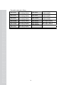
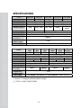
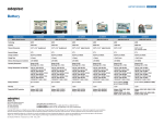
SPECIFICATIONS
Model
Weighing capacity
Readability
Standard deviation
Linearity
Calibration weight (*)
CBL-220S
CBL-320S
220g
320g
0.01g
0.006g
0.01g
200g
Pan diameter(mm)
Main body size(mm)
Main body weight
Stability of sensitivity
(10℃~35℃)
Applicable tem
perature range
Power supply
Model
Weighing capacity
Readability
Standard deviation
Linearity
Calibration weight (*)
Pan diameter(mm)
Main body size(mm)
Main body weight
Stability of sensitivity
(10℃~35℃)
Applicable tem
perature range
Power supply
200g 300g
CBL-620S
620g
0.01g
0.01g
0.02g
500g 600g
CBL-2200S
CBL-3200S
2200g
3200g
0.1g
0.06g
0.1g
2000g
2000g
3000g
100×100
160×124
Approx. 170W×240D×75H
Approx. 2.2kg
±10ppm/℃
5~40℃
AC adapter: 100~250VAC, 47~63Hz, Balance : 12VDC, 0.1A
CBL120H
120g
CBLCBL220H
320H
220g
320g
0.001g
0.001g
0.002g
0.003g
100g
200g
300g
100×100 (With the guard)
Approx. 170W×240D×114H
CBL1200H
1200g
CBL2200S
2200g
0.01g
0.01g
CBL3200H(L)
3200g
0.03g
2000g
3000g
160×124
Approx. 170W×240D×75H
Approx. 2.2kg
±5ppm/℃
±5ppm/℃
±3ppm/℃
(10℃~30℃)
(10℃~30℃)
±3ppm/℃
0.02g
1000g
5~40℃
AC adapter: 100~250VAC, 47~63Hz, Balance : 12VDC, 0.1A(*2)
*1 : Refer to “7.1 Setting the Sensitivity Calibration Weight”.
*2 : 12VDC, 1A ONLY FOR BL3200HL
26
PARTS LIST
Optional accessories
Peripheral devices
Parts name
Parts No.
Printer EP-60A
321-42008-10
RS-232C interface IFB-102A
321-4116-710
100g
321-53445
200g
321-53446
500g
321-53447
For CBL-620S
1kg
321-53448
For CBL-1200H
2kg
321-53449
Calibration weigh
(OIML F1class in the box)
Remarks
For CBL-120H
For CBL-220S
For CBL-220H/320H
For CBL-320S
For CBL-2200S
For CBL-2200H/3200H(L)
For CBL-3200S
Maintenance parts
Parts name
Parts No.
Pan(small) : For 220S, 320S, 120H, 220H, 320H
321-54847
Pan(Large) : For 620S, 2200S, 3200S, 1200H, 2200H, 3200H(L)
321-54846
Pan supporter(small) : For 220S, 320S, 120H, 220H, 320H
321-53908-11
Pan supporter(Large) : For 620S, 2200S, 1200H, 2200H
321-53908-01
Pan supporter(Large) : For 3200S, 3200H(L)
321-53908-02
Guard
321-53901
Guard cover
321-55654
Protection cover
321-53902
Level screw
321-53530
AC adapter
Remarks
OPTION
27
PERIPHERAL DEVICES
1. The EP-60A Electronic Printer
Connection
When connecting this balance to the EP-60A, first be sure to pull up the AC adapter for the balance and
EP-60A. Then connect to data I/O connector as shown below.
Functions
Manual printing
The displayed value is printed whenever the PRINT key is pressed.
Autoprint
In the g display of the balance, when the display is within zero ± 3 count, the display is stabled when
the sample over 20 counts of g display is loaded, the balance automatically prints out. Unload this
sample and wait for the display falls into within zero ± 3 counts, then load a next sample.
Statistic calculation
Pressing the STAT key statistically calculates and prints the data until next pressing of the STAT
key.
See Instruction Manual for Electronic Printer EP-60A for further details.
28
2. The IFB-102A RS-232C Interface
The IFB-102A is used when the balance is connected to a personal computer.
Connection
When connecting the IFB-102A to the balance, be sure to pull up the AC adapter for the balance.
Then insert the plug of IFB-102A into the DATA I/O connector of the balance.
Signal
Pin No.
Signal
I/O
Function
1
FG
2
TXD
Output
Data output
3
RXD
Input
Data Input
4
RTS
5
CTS
6
DSR
Input
Transmitting is possible with(+) polarity.
7
SG
20
DTR
Ground
Ground
Output
29
Receiving is possible with (+) polarity
Example of connection
The above connection is one of examples. This may be different slightly depending on the personal
computer connected to be balance.
Example of programming
The following example deals with such a program that the display value of balance is
being displayed on the personal compute screen whenever the (SPACE) key of personal computer is
pressed.
Baud rate : 1200 bps
Parity : none
Delimiter : CR
(“ ” means space.)
◆ IBM PC/AT
10
20
30
40
50
60
70
OPEN "COM1:1200,N,8,1"
Z$=INKEY$
IF Z$≠” ”
THEN 20
PRINT #1,“D05”
INPUT #1,A$
PRINT A$
GOTO 20
AS
#1
◆ NEC PC-9801 VM2
10 OPEN "“COM:N81NN” AS #1
(20 line and under the same IBM/PC/AT)
Setting baud rate (1200BPS) by personal computer’s memory switch.
30
3. Input/output Format
means space and DL means delimiter.
Input data
Command code + DL → Refer to “16.5 Command Code”.
Output data
◆ For mass display
S-
1000.00g
DL
Unit
At 1-byte
Unit +
At 2-byte
Unit
At 3-byte
Unit
At plus
Space(
At minus
Minus(-)
At stable
S
At unstable
U
)
Polarity
Stability information
(only at output with stability
information)
◆ For
,
display
DL
U-
At plus
Space(
At minus
Minus(-)
At stable
S
At unstable
U
Polarity
Stability information
(only at output with stability
information)
Data format
◆ ASCII(JIS) code
◆ Baud rate, parity, and delimiter change depending on menu selection.
31
)
4. Command Code
Described in this section are the command codes which can be used when your CBL balance is
connected to a computer via the IFB-102A RS-232C interface.
CAUTION : The use of characters other than those described here will cause errors in weighing and
data transfer procedures. If an improper code is mistakenly entered, disconnect the balance power cable
for 10 seconds, then reconnect.
Command
code
Function
Description
T
Taring
Equivalent to the TARE key
D05
Print (output once)
Equivalent to the PRINT key
D06
Autoprint
Refer to “16.1 The EP-60A Electronic Printer”.
D01
Continuous output
D09
Output stop
D07
D03
Continuous output of data in the balance at every
approx. 100 ms.
For less than 1200 bps, it becomes approx. 150 ms.
Autoprint or continuous output is canceled.
Single output with stability
Information
Continuous output with
stability information
Q
ON/OFF selection
{
Echo back
Printing is made once with stability information.
Continuous printing is made with stability
information.
Toggles between standby state and measurement
state.
Characters from these command codes until
delimiter are received and transmitted by every
character.
By use this command, message of personal
computer is able to print out EP-60A.
Characters length is under 16 characters, including
delimiter.
}
32
MEMO
33
MEMO
34
35
36