1
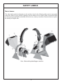
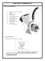
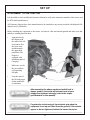
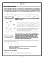
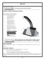
WOOD CHIPPER
Operation, Service,
& Parts Manual
For Model 420
June 2008
Form: 420Chipper.indd
TABLE OF CONTENTS
PAGE
General Information ................................................................................... 1 - 2
Introduction ........................................................................................... 2
Symbols .................................................................................................. 2
Safety Labels ................................................................................................. 3 - 4
Technical Features .............................................................................................. 5
Terminology........................................................................................................ 6
Main Parts Terminology ...................................................................... 6
Identification Plate................................................................................ 6
Safety ........................................................................................................... 7 - 9
Allowed Use ........................................................................................... 7
Improper Use ........................................................................................ 7
Safety in the Workplace........................................................................ 7
Operator's Requirements ..................................................................... 7
General Safety Rules..................................................................... 8 - 10
Set-Up .......................................................................................................11 - 12
Attachment to the Tractor .................................................................11
Driveline Attachment .........................................................................12
Starting Up ...........................................................................................12
Feeding System ....................................................................................13
Transport & Storage ...........................................................................13
Maintenance ..............................................................................................14 - 19
Maintenance Schedule ........................................................................14
Lubrication ...........................................................................................15
Blades ............................................................................................16 - 17
Belt Tension Check.............................................................................18
Spare Parts Ordering ..........................................................................18
Torque Specifications .........................................................................19
Troubleshooting ..................................................................................19
Spare Parts .................................................................................................20 - 24
Chipper Breakdown....................................................................20 - 22
Driveline Breakdown..................................................................23 - 24
Limited Warranty .............................................................................................25
GENERAL INFORMATION
Dealer Stamp
No part of this manual shall be reproduced, copied or disseminated by any means, without
Gearmore's prior authorization in writing.
Gearmore reserves the right to make any necessary changes without giving prior notice, in
order to optimize the quality and safety features and does not commit itself to updating this
manual every time a change is made.
This booklet provides a thorough and accurate description of the instruction and maintenance
activities to be carried out on the chipper you purchased. We congratulate you on your choice
and urge you to thoroughly familiarize yourself with and follow the instructions contained in
this manual. This will assure you a long, safe and trouble free working life for your chipper.
Gearmore shall not assume any responsibility should problems arise as a result of lack
of compliance with the instructions and/or operator's negligence.
The manual is divided in chapters and paragraphs and the pages are numbered, thus offering
accurate and precise information.
The requested information can be easily found by searching the key words or referring to the
table of contents.
1
GENERAL INFORMATION
INTRODUCTION:
The Model 420 Chipper was designed to chip branches up to 4 inches in diameter
The chippers are assembled for operation with 540 PTO R.P.M. tractors only (rated PTO up to
45 H.P.) and supplied with Cat. 1 lift pins for tractor attachment.
The chippers can fit Cat. 1 quick attach hitch by using suitable bushings to adapt diameters of
lift pins.
SYMBOLS:
This booklet contains three "safety graphic symbols" which highlight the relevant danger levels
or important information:
____________________________________________________________________________________________
It draws the operator's attention to situations which
can jeopardize people's safety.
_____________________________________________________________________________
_____________________________________________________________________________
It draws the attention to situations which jeopardize
the machine efficiency but not people's safety.
_____________________________________________________________________________
_____________________________________________________________________________
It highlights general information which does not
endanger people's safety or the efficiency of the parts.
_____________________________________________________________________________
2
SAFETY LABELS
SAFETY LABELS:
The safety labels and the information on the machine, listed in the following table, must be necessarily
carried out; failure to carry out these warnings can cause death or severe injuries. Make sure that the labels
are always present and legible, should this not be the case, contact your nearest Gearmore dealer to replace
the missing or illegible ones.
Note: Shown with optional hopper extension
3
SAFETY LABELS
1
Attention: Read carefully all
instructions and safety rules
before using the machine.
3
Hooking point for the machine's lifting.
5
ENTANGLEMENT HAZARD
To prevent serious injury or
death: Do not unbolt or remove
safety shields while engine is
running
6
8
10
2
4
Danger of hands injuries; do
not open or remove the safety
protections while the machine
is operating.
Attention: Read carefully all
instructions and safety rules
before using the machine. Stop
engine and remove key before
maintenance or repair works.
Wear eyeglasses or face guard
for eyes and face protection and
head guard to protect hearing.
Operate only with 540 rpm
PTO to avoid injury or machine
damage.
7
Thrown objects; Keep a safety
distance from the machine.
9
Danger of hands injuries:
Keep safety guards in position
while operating.
Other Labels:
4
ROTATING DRIVELINE
Contact can cause death
KEEP AWAY!
Do not operate without:
•All driveline guards, tractor
and equipment shields in place
•Driveline securely attached at
both ends
•Driveline guards that turn
freely on driveline
KEEP AWAY
THROWN OR FLYING
OBJECTS
To prevent serious injury or
death:
• Do not operate if all safety
shields are not installed
• Stop machine if anybody
comes within 100 feet
TECHNICAL FEATURES
TECHNICAL FEATURES
A:
B:
C:
D:
Minimum Horsepower Required:
Diameter of Material:
Hopper Dimension - Width x Height:
Feeding System:
Feeding Opening - Width x Height:
U.S.
45"
50"
57"
76"
20 H.P.
4 ½" max.
27" x 24"
Manual Gravity
5 ¾" x 8 ¼"
4
1600 rpm
140 ft./sec.
140#
20"
Number of Blades:
Flywheel Speed:
Knives Tip Speed:
Flywheel Weight:
Flywheel Diameter:
Flywheel Thickness:
1 ¼"
Cat. 1
Cat. 1
540 rpm
600#
3-Point Hitch:
Quick 3-Point Hitch:
Power Take Off:
Weight:
5
METRIC
1150 mm
1250 mm
1440 mm
1920 mm
20 H.P.
115 mm
700 x 610 mm
Manual Gravity
146 x 210 mm
4
1600 rpm
42.3 m/s
64 kg
505 mm
32 mm
Cat. 1
Cat. 1
540 rpm
276 kg
MAIN PARTS TERMINOLOGY
MAIN PARTS TERMINOLOGY:
A
B
C
D
E
F
G
H
I
L
M
N
Hopper Extension/Cover (Optional)
Hopper
Chipper Housing
Chipper Base
Lower 3rd Point Hitches
PTO at 540 rpm
Upper 3rd Point Hitch
Transmission Cover
Knives Housing
Blower Discharge Tube
Exit Deflector
Deflector Adjustment
IDENTIFICATION PLATE
An identification plate is placed on every chipper:
420
_______________________________________________________________________________
When asking for information or technical service,
always specify the machine type and width.
_______________________________________________________________________________
6
SAFETY
ALLOWED USE:
Gearmore chippers taken into account in this instruction manual, are equipments designed to chip wood's
residuals from pruning and residuals from packaging or from other structures made of wood and free of
nails.
Any other use jeopardizes the operator's safety and the machine integrity.
IMPROPER USE:
When using Gearmore Chippers, it is particularly forbidden:
-
The attachment to tractors of unsuitable power or weight.
To assemble the machine without securing the adjustment links of the
3-point hitch of the tractor.
To chip materials different from wood.
To introduce pieces of wood of bigger dimensions compared to the machine's capacity.
To use the machine without having placed the relevant pins and cotter pins
where required.
To lift the machine when the power takeoff is engaged.
To approach rotating parts when wearing inappropriate work clothing.
To get on the machine while it is being used or transported.
SAFETY
SAFETY IN THE WORKPLACE:
Most of the accidents which take place while the operator is using the machine or the equipment or during
their maintenance or repair are caused by a lack of compliance with the basic safety precautions. It is
necessary, therefore, to become more and more conscious of the potential risks of one's action by constantly
paying attention to one's own actions and their effects.
If potentially dangerous situations are known, accidents can be prevented!
OPERATOR'S REQUIREMENTS:
All operators using the equipment must be competent and necessarily meet the following features:
Physical: good eyesight, coordination and capability of carrying out all functions required for the machine's
use.
Mental: Capable of understanding and applying the established rules and safety precautions. Users must
pay attention and be sensible for their own and other people's safety.
Training: users must have read and studied this manual, any enclosed graphs and schemes and its
identification and danger plates. They must be skilled and trained on any use or maintenance activities.
7
SAFETY
WORK CLOTHING:
When working and especially when executing repair or maintenance activities, it is necessary to wear the
following clothing and safety accessories:
-
Overalls or other comfortable clothing, not too loose to
prevent the possibility that parts of them might be caught
in the moving parts.
-
Protective gloves for hands.
-
Protective glasses or faceplate to protect eyes and face.
-
Protective helmet for the head.
- Ear protections to safeguard hearing
______________________________________________________________________________________
Wear only personal safety accessories in good condition
and complying with the rules in force.
______________________________________________________________________________________
GENERAL SAFETY RULES
ALWAYS CONSIDER THE FEATURES OF THE AREA WHERE WORK IS TAKING PLACE:
-
Having to attach the equipment on the spot, it is necessary to arrange a flat and compact
area of sufficient dimensions.
-
When the equipment is running, it is forbidden to stand within the field of action of the chipper
or of the other accessories of which it is provided with.
PREPARE THE WORK:
-
Before and when working, do not drink alcohol, take drugs, or any other substances which may
alter your capability of working with machine tools.
-
Be sure to have sufficient fuel, to prevent a forced stopping of the machine, maybe during a
critical movement.
-
Do not use the equipment under unsafe conditions. For instance, it is forbidden to execute
makeshift repair activities just to start working; it is forbidden to work at night with an
insufficiently illuminated working area.
8
SAFETY
WHEN WORKING OR DURING THE MAINTENANCE ACTIVITIES IT IS NECESSARY TO REMEMBER:
-
The labels and stickers providing instructions and pointing out the dangers, must not be
removed, hidden, or made illegible.
-
Do not remove, except in case of maintenance, the safety devices and protective covers.
When it is necessary to remove them, stop engine, handle with care and reassemble them
properly before restarting the engine and using the equipment.
-
It is forbidden to lubricate, clean and adjust the moving parts while they are running.
-
During maintenance or adjustment activities on the equipment it is forbidden to use hands for
executing operations for which there are specific tools.
-
Do not use tools in bad condition or inappropriately, for instance pliers rather than
wrenches, etc.
-
When maintenance or repairs are completed check out that no tools, wiping rags, or other
materials are left inside spaces or guides with moving parts.
-
While using the equipment, it is forbidden to make more than one person give directions
and make signals. The eventual directions and signals relating to the load handling must be
given by one person only.
-
Do not unexpectedly call an operator while he is working if not necessary; it is forbidden as
well to frighten or throw objects at the operator, even if just for fun.
-
Watch out for those who are present, especially the children!
-
Always make sure that no people stand within the equipment's ray of action.
-
Do not make people get on the machine.
-
When the equipment is not needed, stop the vehicle's engine, park it on flat ground with first
speed and parking brake on, with the machine rested on the ground and PTO disengaged.
-
Do not clean, lubricate, repair or adjust with the engine running and the machine lifted.
-
Do not stretch your hands into the chipper while it is working.
-
Short wooden parts must be pushed towards knives using longer wooden parts or by means of
proper pusher device.
9
SAFETY
-
Small wooden fragments must be pushed in slowly and longitudinally in order to avoid
that splinters of wood or other material are thrown against the user.
-
Do not use the machine indoors in order to prevent smoke poisoning from the engine
combustion.
-
Foreign bodies, such as pieces of metal or stones, must be removed before starting the
machine.
-
Remove protection cover only when the machine is completely stopped from inertia
motion and after having disconnected the drive shaft and removed the key from the engine.
-
Use the chipper only when wearing proper clothing and after having worn suitable
protection for hands, eyes, ears, and head.
-
During transporting chipper blower discharge tube must be oriented so that it does not
stretch out from the outline of the machine.
-
When transporting chipper strictly comply with regulations of the area where you operate.
The manufacturer declines all responsibility for a lack of compliance with these instructions.
10
SET UP
ATTACHMENT TO THE TRACTOR
It is advisable to read carefully this Operator's Manual as well as the instruction manuals of the tractor and
the PTO shaft manufacturers.
All Gearmore chippers have been manufactured to be attached to any tractor provided with hydraulic lift
and universal 3-point hitch.
Before attaching the equipment to the tractor, set both on a flat and smooth ground and make sure that
nobody is standing between them.
•
Approach slowly
the chipper with
the arms of the lift
and connect first
the lower arms
and then attach
the upper third
point hitch. The
chipper is
equipped with
attachment pins of
Category1.
•
Make sure you fix
the pins with the
corresponding
klik pins.
Lock the arms of
the lift with proper
chains turnbuckle
or tensioners.
_____________________________________________________________________________________
•
After executing the above-mentioned activities it is
always good to check that all bolts and nuts of your
chipper are tightened strongly (refer to the torque
specifications in this manual).
________________________________________________________________________________________
_____________________________________________________________________________________
Pay attention to the tractor's front wheels grip when the
equipment is set up and lifted from the ground; if the wheels
appear to be too lightened, ballast the tractor front part.
____________________________________________________________________________
11
SET UP
DRIVELINE ATTACHMENT
Before assembling the PTO shaft, it is very important to check out that its number of revolutions and direction
of rotation match those of the tractor. Also, read carefully the instruction manuals of the PTO shaft and the
tractor's manufacturers. Before starting work, check the presence of the safety guards on the power takeoffs
of the machine, of the PTO shaft and of the tractor. Check in particular that the safety guards cover the PTO
shaft throughout its extension.
_________________________________________________________________________________
When at their maximum extension, the safety guards' plastic
tubing shall overlap at least 1/3 of their length. When in their
maximum closing position, the minimum clearance allowed
shall be 3/4" (Fig. 1).
_________________________________________________________________________________
Fig. 1
Check out that the PTO shaft minimum and maximum length are the
ones required by the machine-tractor coupling. Should problems
arise, contact your Gearmore dealer. After installation, secure safety
guards both to the tractor and the machine using the special chains
and make sure that they pivot freely. If the PTO shaft is equipped
with other safety devices, such as a slip clutch, be sure to install
them on the working machine side. As for the PTO use and
maintenance refer to the relevant booklet.
_________________________________________________________________________________
These operations shall be made only on working ground
and only after having stopped the engine, disengaged the
PTO and pulled the parking brake. If necessary, lift the
machine from the ground, but in order to avoid risks for
people, place it on supports thus preventing any injuries
that might be caused by its sudden fall.
__________________________________________________________________________
CHECKS PRIOR TO STARTING UP
Before starting the chipper check the following:
►The machine is properly connected.
►It is firmly rested on the ground.
►The chipper is parallel to the ground in order to avoid major stress on the PTO.
►The knives are sharpened.
►The discharge tube is correctly mounted and positioned.
STARTING UP OF THE CHIPPER
When all setting up operations are completed, your machine is ready to be used.
At this point it is possible to engage the PTO and work the machine at full capacity.
12
SET UP
_____________________________________________________________________________________
Use the power take off only at 540 rpm.
____________________________________________________________________________
MATERIAL FEEDING SYSTEM AND CHIPPING
Before starting to chip make sure the
unit has reached 540 rpm PTO speed.
• After having correctly
oriented the blower
discharge tube, open
the hopper cover.
• Accurately select the
wooden material to be
chipped and do not
exceed the maximum
cutting diameter of 4 ½".
• Small branches can be
kept together and put in
simultaneously with their
butt end turned towards the
entrance.
• Absolutely avoid pushing
the branches down the
hopper slide using your
hands. Use other pieces of
wood and if necessary,
use proper pusher device.
_____________________________________________________________________________________
Before putting parts to be chipped into the hopper, remove
parts different from wood so that knives are not damaged.
____________________________________________________________________________
ROAD TRANSPORT
While transporting the machine it is very important to follow the road traffic code of the area where you
operate.
SET ASIDE / STORAGE
If the chipper will not be used for a long period of time, we advise to:
1. Wash the machine accurately and dry it.
2. Check out all equipment and replace damaged or worn parts.
3. Tighten strongly all bolts and nuts (See torque specifications chart).
Make an accurate greasing and at last protect the whole machine with a tarpaulin in a building. Store it in a
dry place. Following the instruction will allow you to find the chipper always in good conditions whenever
you use it.
13
MAINTENANCE
Maintenance is a fundamental operation to extend life and performances of any agricultural implement;
taking care of the machine grants you not only a good work condition, but also a longer life of the equipment and greater safety in the workplace.
The operating times indicated in this manual have just an informative character and are referred to normal conditions of use; they can thus undergo variations according to the type of service, to the more or
less dusty environment, to seasonal factors, etc.
MAINTENANCE SCHEDULE
EVERY 10 HOURS OF WORK
-
At the end of every working day it is advisable that you clean accurately the machine so that
its parts are always in good working condition.
Grease crosses on the PTO shaft.
Make a general inspection to verify possible hydraulic oil leaks or the presence of damaged
parts, when it applies.
Make sure the knives are in good condition, sharpened and perfectly fixed by the tightening
bolts.
EVERY 25 HOURS OF WORK
-
Grease the driveshaft crosses through the special lubricating zerks.
Grease the transmission shaft through the proper lubricating zerks.
EVERY 50 HOURS OF WORK
-
Check to make sure that the belts are tightened.
Check that all bolts and nuts are correctly tightened.
MAINTENANCE INTERVENTIONS
_________________________________________________________________________________
Before executing maintenance activities on the machine,
stop engine, disengage PTO, pull parking brake, and place
the equipment on the ground in horizontal position.
_________________________________________________________________________________
14
MAINTENANCE
_________________________________________________________________________________
Before injecting lubricating grease into the zerks,
clean them accurately to prevent mud, dust, or other
foreign matters from mixing with the grease, thus
diminishing the lubrication effect.
_________________________________________________________________________________
GREASING
Lubricate the machine regularly with a high quality lithium based grease to keep it efficient and extend its
life and performance.
Grease the following areas every 25 hours or sooner, if operated in extreme conditions; taking care to not
over grease bearings which could damage the seals.
-
A, B (Picture 1) Transmission shaft supports.
C, D (Picture 2 - 3) Flywheel shaft supports.
E (Picture 4) Blower discharge tube base.
Picture 1
Picture 2
Picture 4
Picture 3
15
MAINTENANCE
BLADES CHECK
To assure a perfect functioning of the chipper check often that its blades are in good conditions, sharpened
and perfectly fixed by the locking bolts.
To inspect the rotor and the blades condition, please proceed as described below:
• Stop the machine.
• Disengage the PTO shaft and remove
the tractor ignition key.
• Remove the locking screw of the
flywheel housing.
• Grab the top half of the housing by
the handles and slowly open the
cover to maximum open position.
• Carefully rotate the flywheel checking
the condition of every single blade.
SHARPENING AND REPLACEMENT OF BLADES
A poor performance of the chipper usually depends on its blades wear.
To disassemble the blades, please proceed as follows:
• Repeat previous point regarding check.
• Rotate flywheel until blade screws are accessible.
• Remove fixing screws and pull out the blade.
• Sharpen or replace the blades.
• Install the new blades with the hardware that was included.
• Repeat operation for the remaining blades.
16
MAINTENANCE
Fig. 5
If the blades are worn, you should
then proceed with their
sharpening.
In case blades are particularly
worn or damaged, replace them with
genuine Gearmore blades.
1/4"
_________________________________________________________________________________
Blade sharpening must be done with suitable machines
that can guarantee a correst sharpening to insure the
angle indicated (Fig. 5).
_________________________________________________________________________________
Every time blades are removed (disassembling/reassembling), before starting the machine again, it is
advisable to check and adjust the distance between blade and bed knife. To adjust bed knife position
proceed as follows;
•
•
•
•
•
Loosen locking screws (4).
Rotate the rotor (1)
bringing the blades (2)
near the bed knife (3).
Adjust the position of the
bed knife (3) by means
of adjusting nuts (5)
making sure that distance
between blade and
bed knife is included
between .063 and .126.
Make sure that this
distance is the same for
all blades.
Block adjusting nuts (5)
and tighten locking screws
(4) with a torque wrench
per the torque specification
chart.
.063 to .126
17
MAINTENANCE
BELT TENSION CHECK
Belts have an automatic spring tensioner and need a check on the condition of springs.
To increase or decrease tension of belts proceed as follows:
• Stop the machine.
• Disengage the PTO shaft and
remove tractor ignition key.
• Take off screws of the two
transmission covers, upper
and lower.
• Remove the two covers.
• Adjust on the nuts (A) of rod (B)
which is threaded to stretch or
extend the spring (C) with a power
of 20 lb. (9kg).
• If the spring is slackened, it is
necessary to replace it; first it is
necessary to disassemble
the threaded rod.
• Block the rod washers.
• Reassemble the two transmission
covers and tighten the relevant screws.
SPARE PARTS ORDERING
To order spare parts, please see parts section in this catalog.
Request of spare parts must be made to a Gearmore dealer and must always be complete with the following
information:
- Type and width of the implement.
- Part number of the needed spare part. If not in possession of this number, you can replace it
with the number of the table where the part is represented and the correspondent reference.
- Denomination of the needed part and desired quantity.
18
MAINTENANCE
TORQUE SPECIFICATIONS
For correct hardware tightening on the Chipper,
we suggest the use of a suitable torque wrench
and the applicable torque as listed in the
table.
M-THREADED SCREW / BOLTS
Bolt Grade
8.8
10.9
Thread
Nm
lb / ft
Nm
lb / ft
M6
11
8.5
17
12
M8
28
20
40
30
M10
55
40
80
60
M12
95
70
140
105
M14
150
110
225
165
M16
240
175
305
225
M18
330
250
475
350
TROUBLESHOOTING
PROBLEM
POSSIBLE CAUSE
Not chipping cleanly or flywheel Dull knives.
plugging.
Bed knife dull or rounded.
Bed knife not adjusted properly.
Unit will not feed.
Limb forks too wide.
Chipper requires excessive
power or stalls.
Chipper vibrates.
Plugged flywheel.
Obstructed discharge.
Improper blade clearance.
Material balled up on flywheel.
Broken or loose part.
Chipper RPM slows, but tractor
RPM does not.
Excessive belt wear.
Drive belts are slipping
Dull knives.
Belt tension too loose.
Pulleys not in alignment.
Pulleys damaged or worn.
Rotor will not turn.
Plugged rotor.
Obstructed discharge.
Drive belts loose or broken.
19
REMEDY
Sharpen or replace knives.
Sharpen or reverse bed knife.
Adjust to clearance of .063 to .126
Remove from hopper and trim off
forks.
Clear flywheel, then feed material
more evenly.
Clean out discharge chute.
Adjust clearance of bed knife.
Clean flywheel with putty knife or
orther tool.
Access flywheel and repair what is
required.
Tighten belts. Replace
Sharpen or replace knives.
Replace belts or spring.
Align pulleys with straight edge.
Replace pulley or pulleys in
question.
Clear rotor then feed material more
evenly.
Clean discharge chute.
Replace belts and/or spring.
PARTS BREAKDOWN
20
PARTS LIST
REF.
1
2
3
4
5
6
7
8
9
10
11
12
13
14
15
16
17
18
19
20
21
22
23
24
25
26
27
28
29
30
31
32
33
34
35
36
37
38
39
40
41
42
43
44
45
46
QTY.
2
1
1
10
12
2
1
3
1
1
1
8
4
1
8
4
28
7
6
1
7
1
2
2
2
1
1
1
12
1
1
1
2
2
2
2
2
2
1
1
1
9
2
1
1
2
PART NO.
6721057
6363560
5642901
34106014
34120014
2020040
5002906
31514050
6384065
5402900
6330655
34129012
5852900
5932900
31508030
5812900
34120008
34121008
31508016
5002908
34108008
5132916
33108020
6320020
2226204
5782901
5002907
5132917
31508020
6363580
5642900
5302901
2020035
31512040
6350010
5302900
34120022
34106022
4301589
6351004
5002905
34106012
34100010
33710096
5215701
31514070
DESCRIPTION
Belt BX-57
Tapered Locking Unit VK 700 35/60
Drive Pulley BX100 x 2
Stop Nut M14 x 2 DIN 982 6
Washer UNI 6592 M14
Bearing UCFL/208
Tensioner Belt Support
Screw UNI 5739 M14 x 50 8.8
Tapered Locking Unit VK 700.1 40/65
Drive Pulley Shaft
Elastic Pin UNI 6873 6 x 55
Stop Nut M12 x 1.75 DIN 6927 8
Flywheel Blade
Blade Disk
Screw UNI 5739 M8 x 30 8.8
Chipper Blade
Washer UNI 6592 M8
Washer UNI 1751 M8
Screw UNI 5739 M8 x 16 8.8
Upper Transmission Cover
Stop Nut M8 DIN 985 6
PTO Shield
Wing Screw M8 x 20 UNI 5449
Circlip External D20 DIN 471
Bearing 6204 2RS
Tensioning Roller
Belt Tensioner
Lower Transmission Cover
Screw UNI 5739 M8 x 20 8.8
Tapered Locking Unit VK 156 35/80
Drive Pulley BX315 x 2
Drive Pulley Shaft
Bearing UCFL/207
Screw UNI 5739 M12 x 40 8.8
Release Pin D.10
Pin, 3rd Lower Point
Washer UNI 6592 M22
Stop Nut M22 DIN 982 6
Pin, Upper 3rd Point
Cotter Pin D.4
3 Point Hitch
Stop Nut UNI 7473 M12
Nut UNI 5587 M10
Screw M10 L=96
Belt Tensioner Spring
Screw UNI 5739 M14 x 70 8.8
21
PARTS LIST
REF.
47
48
49
50
51
52
53
54
55
56
57
58
59
60
61
62
63
64
65
66
67
68
69
70
71
72
73
74
75
76
77
78
79
80
81
82
83
84
85
86
87
88
89
90
91
92
QTY.
8
1
1
1
9
1
1
1
1
2
2
12
1
1
1
3
1
1
1
1
1
1
2
1
1
2
5
1
8
1
2
1
4
6
11
1
1
3
1
1
1
1
1
1
1
8
PART NO.
31712040
5132905
5132926
EAX47048-8007
34108010
5332136
5002134
5832138
5002073
6601020
6560010
34120010
31510035
34120016
5532902
34106010
5532901
31510030
5002904
31510025
5132901
6320035
31514045
31514055
5002901
31912035
31512030
31512035
34120012
5002900
34121012
5002902
34129008
33010025
34106008
5832902
5002910
31508025
5132927
5782900
5832906
5002911
5002909
6615624
8855001
34026008
DESCRIPTION
Screw M12 x 40 UNI 5931 8.8
Bearing UCFL Support
Bearing UCFL Shield
AX4 480/733 1024010-1504260 CP SS
Stop Nut M10 DIN 985 6
Deflector Tie Rod
Deflector
Deflector Adjusting Lever
Exit Chute
Knob M10 X 20
Grease Nipple M10 x 1.5 UNI 7663-A
Washer UNI 6592 M10
Screw UNI 5739 M10 x 35 8.8
Washer UNI 6592 M16
Bushing
Stop Nut UNI 7473 M10
Bushing
Screw UNI 5739 M10 x 30 8.8
Chipper Cover
Screw UNI 5739 M10 x 25 8.8
Shaft Shield
Circlip External f35 DIN 471
Screw UNI 5739 M14 x 45 8.8
Screw UNI 5739 M14 x 55 8.8
Chipper Box
Screw UNI 5933 M12 x 35 8.8
Screw UNI 5739 M12 x 30 8.8
Screw UNI 5739 M12 x 35 8.8
Washer UNI 6592 M12
Chipper Support
Washer UNI 1751 M12
Knocker Tie Rod
Stop Nut M8 x 1.25 DIN 6927 8
Screw UNI 5731 M10 x 25
Stop Nut UNI 7473 M8
Knocker
Chipper Chute
Screw UNI 5739 M8 x 25 8.8
Anchor Angular
Chute Protection
Anchor Plate
Chute Cover (Optional)
Cover Hinge
Gas Spring
Chute Cover Kit (Optional)
"Schnorr" Washer M8
22
DRIVELINE
REF.
QTY.
1
1A
2
3
4
5
6
7
8
9
10
11
12
13
14
15
16
17
18
19
20
21
22
1
1
2
1
1
1
1
1
1
1
1
2
2
2
2
1
1
1
1
2
1
1
1
PART NO.
DESCRIPTION
1024010
1581038
1004020
1704027
6330860
1524034
1525034
6330855
1704029
1504260
1784710
1211733
1781723
1211735
1881709
1773026
1872026
1784711
96SS4026
1006065
1140001
1140003
1140910A
Yoke Assembly (Tractor End)
Push Pin Kit
Cross Assembly
Outer Tube Yoke
Roll Pin 8 x 60 DIN 1485 (Outer Tube)
Outer Tube
Inner Tube
Roll Pin 8 x 55 DIN 1485 (Inner Tube)
Inner Tube Yoke
Safety Device; Free Wheel
Tube Bearing (Outer Tube)
Stiffening Ring
Soft Standard Cone
Safety Ring
Safety Sleeve
Outer Tube Shield
Inner Tube Shield
Tube Bearing (Inner Tube)
Complete Protection
Anti-Rotation Chain
Outer Decal
Inner Decal
User Manual
23
DRIVELINE - SAFETY DEVICE
REF.
QTY.
1
2
3
4
5
6
7
8
9
10
1
2
2
1
1
1
2
1
1
1
PART NO.
DESCRIPTION
1504240
1326062
1215001
1506132
1706016
1215016
1133011
6320075
6560006
1581038
Outer Body for RF1/4
Key
Flat Spring
Hub 1 ⅜" Z6
Push Pin
Push Pin Spring
Closure Ring
Elastic Ring
Grease Zerk
Push Pin Kit
24
LIMITED WARRANTY
GEARMORE, INC., warrants each new Gearmore product to be free from defects in material and
workmanship for a period of twelve (12) months from date of purchase to the original purchaser.
This warranty shall not apply to implements or parts that have been subject to misuse, negligence,
accident, or that have been altered in any way.
Our obligation shall be limited to repairing or replacement of any part, provided that such part is
returned within thirty (30) days from date of failure to Gearmore through the dealer from whom
the purchase was made, transportation charges prepaid.
This warranty shall not be interpreted to render us liable for injury or damages of any kind or nature,
direct, consequential or contingent, to person or property. This warranty does not extend to loss
of crops, loss because of delay in harvesting or any other expenses, for any other reasons.
Gearmore in no way warranties engines, tires, or other trade accessories, since these items are
warranted separately by these respective manufacturers.
Gearmore reserves the right to make improvements in design or changes in specification at any
time, without incurring any obligations to owners or units previously sold.
GEARMORE, INC.
13477 Benson Ave.
Chino, CA 91710
Always refer to and heed machine operating warning decals on machine.
The serial number of this product is stored in our computer database, thus
submitting a warranty registration card is not required.
CUSTOMER INFORMATION
NAME: _______________________________________________
PURCHASED FROM: __________________________________
DATE OF PURCHASE: _________________________________
MODEL NUMBER: ____________________________________
SERIAL NUMBER: ____________________________________
25